Sign In
Upload
Download
Table of Contents
Contents
Add to my manuals
Delete from my manuals
Share
URL of this page:
HTML Link:
Bookmark this page
Add
Manual will be automatically added to "My Manuals"
Print this page
×
Bookmark added
×
Added to my manuals
Manuals
Brands
AEMC Manuals
Measuring Instruments
6422
User manual
AEMC 6422 User Manual
Ground tester
Hide thumbs
1
2
Table Of Contents
3
4
5
6
7
8
9
10
11
12
13
14
15
16
17
18
19
20
21
22
23
24
25
26
27
28
29
30
31
32
33
34
35
36
37
38
39
40
41
42
43
44
page
of
44
Go
/
44
Contents
Table of Contents
Bookmarks
Table of Contents
Table of Contents
1 Introduction
Battery Installation
Battery Charging (Model 6424)
Desktop Stand
Instrument Interface
Instrument Functions
Buttons and Keys
LCD Display
2 Operation
Voltage Measurement
Resistance Measurement (2P)
Grounding Resistance Measurement (3P)
AC Current Measurement (Model 6424)
3 Specifications
General Reference Conditions
Electrical Specifications
Influences
Uncertainty
Environmental Conditions
Power Supply
Mechanical Specifications
International Standards
Electromagnetic Compatibility (CEM)
4 Maintenance
Cleaning
Repair and Calibration
Technical and Sales Assistance
Limited Warranty
Advertisement
Quick Links
Download this manual
6422
■
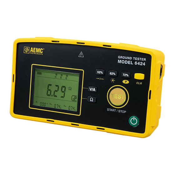
GROUND TESTER
6424
ENGLISH
User Manual
Table of
Contents
Previous
Page
Next
Page
1
2
3
4
5
Advertisement
Table of Contents
Need help?
Do you have a question about the 6422 and is the answer not in the manual?
Ask a question
Questions and answers
Related Manuals for AEMC 6422
Measuring Instruments AEMC 6470-b User Manual
Digital ground resistance and soil resistivity tester (76 pages)
Measuring Instruments AEMC 6416 User Manual
Clamp-on ground resistance tester (41 pages)
Measuring Instruments AEMC 6424 User Manual
Ground tester (44 pages)
Measuring Instruments AEMC 6522 User Manual
Megohmmeters (47 pages)
Measuring Instruments AEMC 6550 User Manual
10kv and 15kv megohmmeters (72 pages)
Measuring Instruments AEMC 6608 User Manual
Phase rotation meter (24 pages)
Measuring Instruments AEMC 6240 User Manual
Micro-ohmmeter (44 pages)
Measuring Instruments AEMC 6240 User Manual
Micro-ohmmeter (32 pages)
Measuring Instruments AEMC 6503 User Manual
Megohmmeter (32 pages)
Measuring Instruments AEMC 6292 Service And Calibration Manual
Micro-ohmmeter (14 pages)
Measuring Instruments AEMC 6292 User Manual
Micro-ohmmeter (48 pages)
Measuring Instruments AEMC 6526 Quick Start Manual
Megohmmeter (13 pages)
Measuring Instruments AEMC 6526 Quick Start Manual
Megohmmeter (17 pages)
Measuring Instruments AEMC 6505 User Manual
Megohmmeter (28 pages)
Measuring Instruments AEMC 6609 User Manual
Phase & motor rotation meter (32 pages)
Measuring Instruments AEMC 6610 User Manual
Phase rotation meter (16 pages)
This manual is also suitable for:
6424
Table of Contents
Print
Rename the bookmark
Delete bookmark?
Delete from my manuals?
Login
Sign In
OR
Sign in with Facebook
Sign in with Google
Upload manual
Upload from disk
Upload from URL


Need help?
Do you have a question about the 6422 and is the answer not in the manual?
Questions and answers