
Related Manuals for Arecont Vision AV2325DNIR


Summary of Contents for Arecont Vision AV2325DNIR
- Page 1 ® MicroBullet Installation Manual Models 1080p AV2325DNIR AV2326DNIR 3 Megapixel AV3325DNIR AV3326DNIR Available from A1 Security Cameras www.a1securitycameras.com email:sales@a1securitycameras.com...
-
Page 2: Table Of Contents
® MicroBullet Installation Manual Contents Package Contents .............................. 3 Camera Overview .............................. 5 Installation ................................ 6 Electrical Box Adapter ............................ 7 Adjusting the Pan, Tilt and Focus ........................ 8 Camera Power Up .............................. 9 Camera Discovery, Setup, and Configuration .................... 1 1 Network Protocols .............................. 1 1 General Remote Focus . -
Page 3: Package Contents
The packaging contains: Reference # Description ® 1x Arecont Vision MicroBullet camera 3x M4x25mm Wood/ Metal Sheet Screw camera 3x M4x25mm Drywall/ Masonry Mounting Anchors... -
Page 4: Warranty Information
VISION’s written authorization; (ii) has not been used in accordance with applicable documentation; (iii) has been subjected to unusual stress, neglect, misuse, abuse, improper storage, testing or connection; or unauthorized repair; or (iv) is no longer covered under the Warranty Period. ARECONT VISION MAKE NO WARRANTIES OR CONDITIONS, EXPRESS, IMPLIED, STATUTORY OR OTHERWISE,... -
Page 5: Camera Overview
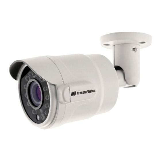
® MicroBullet Installation Manual Camera Overview ® The MicroBullet multi-megapixel camera series delivers 1080p or 3-megapixel resolutions in an extremely compact design. These true day/ night cameras are available with a 2.8-8mm motorized lens, day/night mechanical IR cut filter, and integrated IR LEDs. MicroBullet is ideal for applications with normal to challenging lighting conditions regardless of the time of day. -
Page 6: Installation
® MicroBullet Installation Manual Installation ® The MicroBullet camera can be directly attached onto hard ceilings or walls including wood, plastic, metal and concrete. 1. Determine a secure location to mount the camera. 2. Use the template, anchors, and screws provided to prepare the mounting provisions for the camera installation. -
Page 7: Electrical Box Adapter
® MicroBullet Installation Manual Electrical Box Adapter AV-EBAS(sold separately) and MCD-EBA(sold separately) are used to attach the camera to a common single, double or square electrical box. 1. Use the supplied machine screws from AV-EBAS/ MCD-EBA, match the mounting holes on AV- EBAS/ MCD-EBA with the threaded holes on the electrical box. -
Page 8: Adjusting The Pan, Tilt And Focus
® MicroBullet Installation Manual Adjusting the Pan, Tilt and Focus 1. Loose Hex screws on the camera bracket with the supplied Hex screw L-key, and then adjust the pan, tilt, and rotation position to obtain the desired field of view as shown in Figure 3. NOTE: Do not remove the screws! Figure 3: Loose Hex screws on the camera bracket to adjust the field of view... -
Page 9: Camera Power Up
® MicroBullet Installation Manual Camera Power Up This product should be installed by a qualified service technician in accordance with the National Electrical Code (NEC 800 CEC Section 60) or applicable local code. 1. Connect the camera to a PoE port on 100Mbps network PoE switch using an Ethernet cable as shown in the image below. - Page 10 ® MicroBullet Installation Manual Status Description Flashing Link has been established. Yellow Solid Normal Operation. Flashing Camera has been accessed. Normal operation. Green Solid None None No Connection. NOTE: Wiring methods shall be in accordance with the National Electrical Code/NFPA 70/ANSI, and with all local codes and authorities having jurisdiction.
-
Page 11: Camera Discovery, Setup, And Configuration
CD that came with your camera or available on our website. Network Protocols The Arecont Vision MicroBullet cameras support RTSP, RTP/TCP, RTP/UDP, HTTP, DHCP, TFTP, QoS, IP version 4 (IPv4), IP version 6 (IPv6), and 802.1x. - Page 12 ® MicroBullet Installation Manual QoS – Quality of Service guarantees a certain level of a specified resource to selected traffic on a network. A QoS-aware network prioritizes network traffic and provides a greater network reliability by controlling the amount of bandwidth an application may use. IPv4 –...
-
Page 13: General Remote Focus
Figure 1: Double click via AV IP Utility Figure 2: Type the camera IP address 2. Scroll to the Focus Tab section. ® NOTE: Additional information regarding the Arecont Vision web interface is found separately in the AV IP Utility Web Browser Manual via the Arecont Vision website. -
Page 14: Refined Remote Focus
® MicroBullet Installation Manual Refined Remote Focus 1. For a more refined, detailed focus, scroll to the Video Tab section and select “Enable Digital Zoom Control” radial button. 2. Choose an area that has a lot of objects or an area you have an interest in seeing more details. Left click and drag the box to the area where you want to see finer details. - Page 15 ® MicroBullet Installation Manual 9. When satisfied with the camera’s focus setting, scroll to the Video Tab section and select “Enable Digital Zoom Control” radial button. 10. Double click the image; the video returns to the full field of view. Page | 15 support@arecontvision.com +1.818.937.0700...
-
Page 16: Av Ip Utility Focus Tab
® MicroBullet Installation Manual AV IP Utility Focus Tab Menu Feature Description View Focus Window Allows the user to drag the box to the area where need to be focused on. Manual Zoom/ Focus: Numbers indicate the level of Zooming/ focusing in order to +20, +5, +1, -20, -5, -1 adjust the field-of-view. -
Page 17: Mounting Templates
® MicroBullet Installation Manual Mounting Template Unit: mm Page | 17 support@arecontvision.com +1.818.937.0700 877.CAMERA.8 www.arecontvision.com avsales@arecontvision.com Available from A1 Security Cameras www.a1securitycameras.com email:sales@a1securitycameras.com... -
Page 18: Support
3. Email: support@arecontvision.com 4. Use the Arecont Vision software AV IP Utility located on the CD or available for download at our website (www.arecontvision.com) for camera discovery and setup (see Instruction Manual located on the CD or available on our website).
Need help?
Do you have a question about the AV2325DNIR and is the answer not in the manual?
Questions and answers