Motorola surfboard sbg901 User Manual
Wireless cable modem gateway
Hide thumbs
Also See for surfboard sbg901:
- Datasheet (4 pages) ,
- Setup and configuration manual (7 pages) ,
- User manual (87 pages)
Table of Contents
Advertisement
Quick Links
Advertisement
Table of Contents

Related Manuals for Motorola surfboard sbg901


Summary of Contents for Motorola surfboard sbg901
- Page 1 ® Motorola SURFboard SBG901 Wireless Cable Modem Gateway User Guide...
- Page 2 Safety and Regulatory Information SAFETY AND REGULATORY INFORMATION IMPORTANT SAFETY INSTRUCTIONS When using your equipment, basic safety precautions should always be followed to reduce the risk of fire, electric shock, and injury to persons, including the following: • Read all of the instructions listed here and/or in the user manual before you operate this device. Give particular attention to all safety precautions.
- Page 3 CARING FOR THE ENVIRONMENT BY RECYCLING When you see this symbol on a Motorola product, do not dispose of the product with residential or commercial waste. Recycling your Motorola Equipment Please do not dispose of this product with your residential or commercial waste.
- Page 4 This device may not cause harmful interference, and (2) This device must accept any interference received, including interference that may cause undesired operation. FCC CAUTION: Any changes or modifications not expressly approved by Motorola for compliance could void the user’s authority to operate the equipment.
- Page 5 SECURITY WARNING: This device allows you to create a wireless network. Wireless network connections may be accessible by unauthorized users. Please read the SBG901 User Guide or visit the Motorola website to learn how to protect your network.
- Page 6 EN61000-3-3, EN60950-1, IEC60950-1, ETSI EN 300 328, ETSI EN 301 489-1/-17 © 2008 Motorola, Inc. All rights reserved. No part of this publication may be reproduced in any form or by any means or used to make any derivative work (such as translation, transformation, or adaptation) without written permission from Motorola, Inc.
-
Page 7: Table Of Contents
Contents Safety and Regulatory Information Introduction SBG901 Features ............................13 Easy Setup ..............................14 Network Connection Types......................... 14 Powerful Features in a Single Unit......................14 Sample Hybrid LAN ..........................15 Optional Accessories ..........................15 Front Panel ..............................16 Rear Panel ..............................17 Bottom Label on the SBG901 ........................ - Page 8 Configuring TCP/IP in Windows Vista....................32 Verifying the IP Address in Windows 2000 or Windows XP..............34 Verifying the IP Address in Windows Vista ..................35 Renewing Your IP Address ......................... 35 Wall Mounting the SBG901 ........................36 Wall Mounting Template ........................38 Basic Configuration Starting the SBG901 Configuration Manager (CMGR)................
- Page 9 Backing Up Your SBG901 Configuration ....................58 Advanced Pages Advanced Options Page..........................59 Advanced IP Filtering Page ......................... 61 Advanced MAC Filtering Page ........................62 Setting a MAC Address Filter ....................... 62 Advanced Port Filtering Page ........................63 Advanced Port Forwarding Page......................... 64 Advanced Port Triggers Page........................
- Page 10 Configuring a Wireless Client with the Network Name (SSID) ............95 Troubleshooting Solutions..............................97 Front-Panel LEDs and Error Conditions....................... 98 Contact Us Specifications Glossary Software License Tables SBG901 Front-Panel LED Indicators ......................16 SBG901 Rear Panel Connectors and Indicators..................17 Items Included with Your SBG901......................
- Page 11 Field Descriptions for the Wireless Bridging Page ..................89 Field Descriptions for the Wireless 802.11b/g Wi-Fi Multimedia Page ............90 Field Descriptions for the Wireless 802.11b/g Guest Network Page ............93 Configuring Wireless Clients........................94 Troubleshooting Solutions........................... 97 Front-Panel Lights and Error Conditions ..................... 98 Specifications ............................
- Page 12 Wall Mounting Template..........................39 Status Software Page ..........................47 Status Connection Page..........................48 Change User Information window ......................49 Ping Utility window ............................. 50 Traceroute Utility window ........................... 51 Status Event Log Page..........................52 Basic Setup Page ............................53 Basic DHCP Page............................55 Basic DDNS Page............................
-
Page 13: Safety And Regulatory Information
® Congratulations, you have a Motorola SBG901 SURFboard Wireless Cable Modem Gateway for your home, home office, or small business/enterprise. Applications where the Motorola SBG901 is especially useful include: • Households with multiple computers requiring a network connection and Internet access •... -
Page 14: Easy Setup
Easy Setup It is much easier to configure a local area network (LAN) using an SBG901 than using traditional networking equipment: • The Installation Assistant application on the SBG901 Installation CD-ROM enables easy connection to the cable network and setup for security. •... -
Page 15: Sample Hybrid Lan
• An advanced firewall supporting stateful-inspection, intrusion detection, DMZ, denial-of-service attack prevention, and Network Address Translation (NAT) • Port Forwarding to configure ports to run applications having special network requirements Sample Hybrid LAN The sample LAN illustrated below contains the following devices, all protected by the SBG901 firewall. -
Page 16: Front Panel
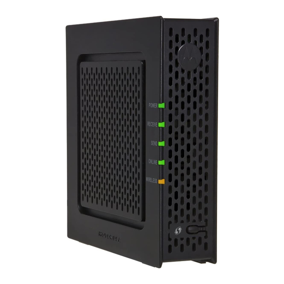
Front Panel The front panel contains indicator lights and a button for client card pairing. The display remains dark until there is a connection or activity on an interface. Figure 2 SBG901 Front Panel LEDs The lights provide status and information about power, communications, and errors: Table 1 SBG901 Front-Panel LED Indicators Light Flashing... -
Page 17: Rear Panel
Rear Panel Figure 3 SBG901 Rear Panel The rear panel contains cabling connectors and the power receptacle. Table 2 SBG901 Rear Panel Connectors and Indicators Item Description ETHERNET Connects to an Ethernet-equipped computer, hub, or switch using an RJ-45 cable connection Connects the SBG901 to a cable wall outlet coaxial cable connection CABLE... -
Page 18: Bottom Label On The Sbg901
Bottom Label on the SBG901 The label on the bottom of the SBG901 contains the Media Access Control (MAC) address, a unique, 48-bit value permanently saved in ROM at the factory to identify each Ethernet network device. To receive data service, you will need to provide the MAC address marked HFC MAC ID to your Internet Service provider. -
Page 19: Wireless Lan
Your maximum wireless operation distance depends on the type of materials through which the signal must pass and the location of your SBG901 and clients (stations). Motorola cannot guarantee wireless operation for all supported distances in all environments. -
Page 20: Wired Ethernet Lan
Wired Ethernet LAN You can easily connect any PC with an Ethernet LAN port to the SBG901 Ethernet connection. Because the SBG901 Ethernet port supports auto-MDIX, you can use straight-through or cross-over cable to connect a hub, switch, or computer. Use category 5, or better, cabling for all Ethernet connections. -
Page 21: Firewall
Firewall The SBG901 firewall protects the SBG901 LAN from undesired attacks and other intrusions from the Internet. It provides an advanced, integrated stateful-inspection firewall supporting intrusion detection, session tracking, and denial-of-service attack prevention. The firewall: • Maintains state data for every TCP/IP session on the network and transport layers... -
Page 22: Wireless Security
• If all of your wireless clients support Wi-Fi Protected Access (WPA or WPA2) encryption, Motorola recommends using WPA2. Otherwise, configure a Wired Equivalency Privacy (WEP) key on the SBG901 and each WLAN client. •... -
Page 23: Getting Started
For information about WLAN setup, see Setting Up Your Wireless LAN. Before You Begin Before you begin the installation, check that the following items were included with your Motorola SBG901 Gateway: Table 3 Items Included with Your SBG901 Item Description Power cord... -
Page 24: Precautions
You must have the latest service packs and patches installed on your computer for your operating system. You will need 75-ohm coaxial cable with F-type connectors to connect the SBG901 to the nearest cable outlet. If a TV is connected to the cable outlet, you may need a 5 to 900 MHz RF splitter and two additional coaxial cables to use both the TV and the SBG901. -
Page 25: Computer System Requirements
Computer System Requirements ® ® ® ® ® You can connect Microsoft Windows , Macintosh , UNIX , or Linux computers to the SBG901 LAN using one of the following: • Ethernet — 10Base-T or 10/100Base-T Ethernet adapter with proper driver software installed. For user with Microsoft Vista™, please note the following information on driver support: Vista OS support Vista Home Basic (32 bit and 64 bit) -
Page 26: Cabling The Lan
Figure 7 Connecting the SBG901 Check that the lights on the front panel cycle through this sequence: Table 4 SBG901 Light Activity During Startup Light Description POWER Turns on when AC power is connected to the SBG901. Indicates that the power is connected properly. RECEIVE Flashes while scanning for the downstream receive channel. -
Page 27: Obtaining An Ip Address For An Ethernet Connection
Automatically retrieve the IP address using the Network DHCP server The Motorola SBG901 gateway provides a DHCP server on its LAN. It is recommended that you configure your LAN to obtain the IPs for the LAN and DNS server automatically. -
Page 28: Local Area Connection Status Window
Figure 8 Local Area Connection Status window 4. Click Properties to display the Local Area Connection number Properties window. Information similar to the following is displayed. Figure 9 Local Area Connection Properties window 5. If Internet Protocol (TCP/IP) is in the list of components, TCP/IP is installed. You can skip to step 8. -
Page 29: Local Area Connection Properties Window
Figure 10 Select Network Component Type window 7. Click Protocol and then click Add. The Select Network Protocol window is displayed. 8. Click Internet Protocol (TCP/IP) and then click OK. The Local Area Connection number Properties window is redisplayed. Figure 11 Local Area Connection Properties window 9. -
Page 30: Configuring Tcp/Ip In Windows Xp
Configuring TCP/IP in Windows XP 1. On the Windows desktop, click Start to display the Start window. 2. Click Control Panel to display the Control Panel window. The display varies, depending on the Windows XP view options. If the display is a Category view, as shown below, continue with step 3. -
Page 31: Network Connections Window
Figure 14 Network Connections window 7. Select Properties from the drop-down menu to display the Local Area Connection Properties window. Be sure Internet Protocol (TCP/IP) is checked. Figure 15 Local Area Connection Properties window 8. Select Internet Protocol (TCP/IP) and click Properties to display the Internet Protocol (TCP/IP) Properties window. -
Page 32: Configuring Tcp/Ip In Windows Vista
Configuring TCP/IP in Windows Vista 1. On the Windows desktop, click Start to display the Start window. 2. Click Control Panel to display the Control Panel window. 3. Double-click Network and Internet and the Network and Internet window is displayed: 4. -
Page 33: Local Area Connection Properties Window
6. Right-click the network connection and select Properties to display the Local Area Connection Properties window: Figure 18 Local Area Connection Properties window 7. If more than one connection is displayed, make sure to select the one for your network interface. -
Page 34: Verifying The Ip Address In Windows 2000 Or Windows Xp
11. Click OK to close the Local Area Connection Properties window. 12. Exit the Network Connections window. 13. Exit the Network and Sharing Center window and the Control Panel. When you complete the TCP/IP configuration, go to Verifying the IP Address in Windows Vista. -
Page 35: Verifying The Ip Address In Windows Vista
Verifying the IP Address in Windows Vista Do the following to verify the IP address: 1. On the Windows Vista desktop, click Start. 2. Click All Programs. 3. Click Accessories. 4. Click Run to display the Run window. 5. Type cmd and click OK to open a command prompt window. 6. -
Page 36: Wall Mounting The Sbg901
Figure 23 Renew IPCONFIG window1 5. Type exit and press ENTER to return to Windows. If after performing this procedure your computer cannot access the Internet, call your cable provider for help. Wall Mounting the SBG901 If you mount your SBG901 on the wall, you must: •... -
Page 37: Printer Settings For Wall Mounting Template
Figure 24 Printer Settings for Wall Mounting Template To print the template only, select Current page as the Print Range. Be sure you print the template at 100% scale. Be sure No Scaling is selected for Scale to paper size. 3. -
Page 38: Wall Mounting Template
10. Slide the SBG901 down until it stops against the top of the keyhole opening. After mounting, reconnect the coaxial cable input and Ethernet connection. Plug the power cord into the +12VDC connector on the cable modem and the electrical outlet. Route the cables so that they are not a safety problem. -
Page 39: Wall Mounting Template
Figure 26 Wall Mounting Template 2 Getting Started This document is uncontrolled pending incorporation in PDM... -
Page 40: Basic Configuration
Basic Configuration The following topics provide information about basic SBG901 configuration: • Starting the SBG901 Configuration Manager (CMGR) • SBG901 Menu Options Bar • Changing the SBG901 Default Password • Getting Help • Gaming Configuration Guidelines • Exiting the SBG901 Configuration Manager For more advanced configuration information, see Configuring TCP/IP Setting Up Your... - Page 41 3. Type admin in the Username field (this field is case-sensitive). 4. Type motorola in the Password field (this field is case-sensitive). 5. Click Login to display the SBG901 Status Connection page. The Status Connection page provides the following status information on the network connection of the SBG901: •...
-
Page 42: Sbg901 Menu Options Bar
Exits the SBG901 Configuration Manager CAUTION: To prevent unauthorized configuration, immediately change the default password when you first configure your Motorola SBG901. SBG901 Submenu Options Additional features for each menu option are displayed by clicking a Submenu Option in the left panel of each page. -
Page 43: Changing The Sbg901 Default Password
To reset the user name and password back to the original factory settings: 1. Select Yes, and then click Apply. 2. You must login with the default user name, admin, and password, motorola, after applying this change. All entries are case-sensitive. -
Page 44: Getting Help
Getting Help To retrieve help information for any menu option, click help on that page. As an example, the Firewall help page is shown below: You can use the Windows scroll bar to view additional items on the help screens. Gaming Configuration Guidelines The following provides information about configuring the SBG901 firewall and DMZ for gaming. -
Page 45: Configuring Port Triggers
2 for PS2 online gaming, designate it as the gaming DMZ host because the ports required vary from game to game. For these games, Motorola recommends configuring the gaming computer or device as a gaming DMZ device. To configure a gaming DMZ device, on the... - Page 46 3 Basic Configuration This document is uncontrolled pending incorporation in PDM...
-
Page 47: Status Pages
Status Pages The SBG901 Status pages provide information about the SBG901 hardware and software, MAC address, cable modem IP address, serial number, and related information. You can also monitor your cable system connection. Additional pages provide diagnostic tools and allow you to change your SBG901 user name and password. -
Page 48: Status Connection Page
Status Connection Page This page provides the HFC and IP network connectivity status of the SBG901 cable modem. You can click the Refresh button in your web browser to refresh the information on this page at any time. Figure 28 Status Connection Page Table 6 Field Descriptions for the Status Connection Page Field Description... -
Page 49: Status Security Page
6. Click Apply to update the user name password. Note: You must login with the default user name, admin, and password, motorola, after applying the restore factory settings change. Status Diagnostics Page This page provides the following diagnostic tools for troubleshooting your IP connectivity problems: •... -
Page 50: Ping Utility
Ping Utility Ping (Packet InterNet Groper) allows you to check connectivity between the SBG901 and other devices on the SBG901 LAN. This utility sends a small packet of data and then waits for a reply. When you Ping a computer IP address and receive a reply, it confirms that the computer is connected to the SBG901. -
Page 51: Traceroute Utility
Traceroute Utility Traceroute allows you to map the network path from the SBG901 Configuration Manager to a public host. Selecting Traceroute from the Select Utility drop-down list will present alternate controls for the Traceroute utility. Figure 31 Traceroute Utility window 1. -
Page 52: Status Event Log Page
Status Event Log Page This page lists the critical system events in chronological order. A sample Event log is shown below: Figure 32 Status Event Log Page Table 7 Descriptions for the Status Event Log Page Field Description Time Indicates the date and time the error occurred Priority Indicates the level of importance of the error Description... -
Page 53: Basic Pages
Basic Pages The SBG901 Basic Pages allow you to view and configure SBG901 IP-related configuration data, including Network Configuration, WAN Connection Type, DHCP , and DDNS. The Backup option allows you to save a copy of your SBG901 configuration on your PC. You can click any Basic submenu option to view or change the configuration information for that option. -
Page 54: Field Descriptions For The Basic Setup Page
Table 8 Field Descriptions for the Basic Setup Page Field Description NAPT mode NAPT is a special case of NAT, where many IP numbers are hidden behind a number of addresses. In contrast to the original NAT, however, this does not mean there can be only that number of connections at a time. -
Page 55: Basic Dhcp Page
Field Description Host Name If the WAN Connection Type is DHCP, enter a Host Name if required by your ISP. Domain Name If the WAN Connection Type is DHCP, enter a Domain Name if required by your ISP. MTU Size Maximum Transmission Unit (MTU) is the largest size packet or frame that can be sent. -
Page 56: Basic Ddns Page
Table 9 Field Descriptions for the Basic DHCP Page Field Description DHCP Server Select Yes to enable the SBG901 DHCP Server. Select No to disable the SBG901 DHCP Server. Starting Local Address Enter the starting IP address to be assigned by the SBG901 DHCP server to clients in dotted-decimal format. -
Page 57: Basic Backup Page
Table 10 Field Descriptions for Basic DDNS Page Field Description DDNS Service Select Disable or wwwDynDNS.org to enable the DDNS Service. User Name Enter your DynDNS user name. Password Enter your DynDNS Password. Host Name Enter your DDNS Host Name. IP Address Lists IP information. -
Page 58: Backing Up Your Sbg901 Configuration
Backing Up Your SBG901 Configuration 1. Type the path with the file name where you want to store your backup file on your computer, or click Browse to locate the file. 2. Click Backup to create a backup of your SBG901 settings. 5 Basic Pages This document is uncontrolled pending incorporation in PDM... -
Page 59: Advanced Options Page
Advanced Pages The SBG901 Advanced Pages allow you to configure the advanced features of the SBG901, including IP Filtering, MAC Filtering, Port Filtering, Port Forwarding, Port Triggers, DMZ Host, and Routing Information Protocol Setup. You can click any Advanced submenu option to view or change the advanced configuration information for that option. -
Page 60: Field Descriptions For The Advanced Options Page
Table 12 Field Descriptions for the Advanced Options Page Field Description WAN Blocking Prevents the SBG901 Configuration Manager or the PCs behind it from being visible to other computers on the SBG901 WAN. Checkmark Enable to turn on this option or uncheck to disable it. IPsec Pass-Through Enables the IPsec Pass-Through protocol to be used through the SBG901 Configuration Manager so that a VPN device (or software) -
Page 61: Advanced Ip Filtering Page
Advanced IP Filtering Page This page allows you to define which local PCs will be denied access to the SBG901 WAN. You can configure IP address filters to block Internet traffic to specific network devices on the LAN by entering starting and ending IP address ranges. Note that you only need to enter the LSB (Least- significant byte) of the IP address;... -
Page 62: Advanced Mac Filtering Page
Advanced MAC Filtering Page This page allows you to define Media Access Control (MAC) address filters to prevent PCs from sending outgoing TCP/UDP traffic to the WAN via their MAC addresses. This is useful because the MAC address of a specific NIC card never changes, unlike its IP address, which can be assigned via the DHCP server or hard-coded to various addresses over time. -
Page 63: Advanced Port Filtering Page
Advanced Port Filtering Page This page allows you to define port filters to prevent all devices from sending outgoing TCP/UDP traffic to the WAN on specific IP port numbers. By specifying a starting and ending port range, you can determine what TCP/UDP traffic is allowed out to the WAN on a per-port basis. Note: The specified port ranges are blocked for ALL PCs, and this setting is not IP address or MAC address specific. -
Page 64: Advanced Port Forwarding Page
Advanced Port Forwarding Page This page allows you to run a publicly accessible server on the LAN by specifying the mapping of TCP/UDP ports to a local PC. This enables incoming requests on specific port numbers to reach web servers, FTP servers, mail servers, etc. so that they can be accessible from the public Internet. -
Page 65: Advanced Port Triggers Page
Advanced Port Triggers Page This page allows you to configure dynamic triggers to specific devices on the LAN. This allows for special applications that require specific port numbers with bi-directional traffic to function properly. Applications such as video conferencing, voice, gaming, and some messaging program features may require these special settings. -
Page 66: Advanced Dmz Host Page
Field Description Target Range Start Port The starting port number of the Port Trigger range. End Port The ending port number of the Port Trigger range. Protocol Choice, TCP, UDP, or Both Enable Select checkbox to activate the IP port triggers. Advanced DMZ Host Page This page allows you to specify the "default"... -
Page 67: Advanced Routing Information Protocol Setup Page
Advanced Routing Information Protocol Setup Page This page allows you to configure Routing Information Protocol (RIP) parameters related to authentication, destination IP address/subnet mask, and reporting intervals. RIP automatically identifies and uses the best known and quickest route to any given destination address. To help reduce network congestion and delays, the Advanced RIP setup is used in WAN networks to identify and use the best known and quickest route to given destination addresses. - Page 68 Table 17 Field Descriptions for the Advanced RIP Setup Page Field Description RIP Enable Enables or disables the RIP protocol. This protocol helps the router dynamically adapt to the changes in the network. RIP is now considered obsolete since newer routing protocols, such as OSPF and ISIS, have been introduced.
-
Page 69: Firewall Pages
Firewall Pages The SBG901 Firewall Pages allow you to configure the SBG901 firewall filters and firewall alert notifications. You can click any Firewall submenu option to view or change the firewall configuration information for that option. For information about how the firewall can affect gaming, see Gaming Configuration Guidelines. -
Page 70: Firewall Web Content Filter Page
Figure 45 Firewall Web Content Filter Page Checkmark Enable for each Web filter you want to set for the firewall, and then click Apply. The Web filters will activate without having to reboot the SBG901 Configuration Manager. Note: At least one Web filter or feature must be enabled for the firewall to be active. -
Page 71: Firewall Local Log Page
Firewall Local Log Page This page allows you to set up how to send notification of the firewall event log in either of the following formats: • Individual e-mail alerts sent out automatically each time the firewall is under attack •... -
Page 72: Firewall Remote Log Page
Firewall Remote Log Page This page allows you to send firewall attack reports out to a standard SysLog server so many instances can be logged over a long period of time. You can select individual attack or configuration items to send to the SysLog server so that only the items of interest will be monitored. -
Page 73: Parental Control Pages
Parental Control Pages The SBG901 Parental Control Pages allow you to configure access restrictions to a specific device connected to the SBG901 LAN. You can click any Parental Control submenu option to view or change the configuration information for that option. Parental Control User Setup Page This page is the master page. -
Page 74: Field Descriptions For The Parental Control User Setup Page
Figure 48 Parental Control User Setup Page Table 20 Field Descriptions for the Parental Control User Setup Page Field Description Add User Adds a user to set the parental controls for a specific user. User Settings Select the user for whom you want to modify access restrictions. Checkmark Enable to select the user. -
Page 75: Parental Control Basic Setup Page
Field Description Session Duration You can set the amount of time a selected user can use the Internet. Inactivity time You can set the amount of inactivity time before the Internet automatically closes for a selected user. Trusted Computers You can enter a selected user’s CPE MAC address so that CPE can access the Internet without being censored by the Parental Control. -
Page 76: Parental Control Tod Access Policy Page
Parental Control ToD Access Policy Page This page allows you to block all Internet traffic to and from specified devices on your SBG901 network based on the day and time settings you specify. You can set policies to block Internet traffic for the entire day or just certain time periods within each day for specific users. -
Page 77: Parental Control Event Log Page
Parental Control Event Log Page This page displays the Parental Control event log report. The event log is a running list of the last 30 Parental Control access violations, which include the following items on Internet traffic: • If the user's Internet access is blocked (time filter) •... - Page 78 8 Parental Control Pages This document is uncontrolled pending incorporation in PDM...
-
Page 79: Wireless Pages
Wireless Pages The SBG901 Wireless Pages allow you to configure your wireless LAN (WLAN). You can click any Wireless submenu option to view or change the configuration information for that option. WPA or WPA2 encryption provides higher security than WEP encryption, but older wireless client cards may not support the newer WPA or WPA2 encryption methods. -
Page 80: Encrypting Wireless Lan Transmissions
You must configure the identical WEP key to the SBG901 on the SBG901 each wireless client. If all of your wireless clients support WPA encryption, Motorola recommends using WPA instead of WEP because WPA: • Provides much stronger encryption and is more secure •... -
Page 81: Wireless 802.11B/G Basic Page
(such as network name and encryption key or WPA pass phrase) on each Wi-Fi device. Motorola SecureEasySetup technology dramatically simplifies installation by automating the configuring new wireless networks processes and adding devices to existing networks. - Page 82 Field Description Network Type Selecting Closed prevents the network name from appearing in a wireless client’s "Available Wireless Networks" list. Only clients who already know the network name will be able to connect. Closed disables the SSID broadcast in beacon packets. Selecting Open allows broadcasting to the SSID in beacon packets.
-
Page 83: Wireless 802.11B/G Privacy Page
Wireless 802.11b/g Privacy Page This page allows you to configure the WEP keys and/or passphrase. Figure 53 Wireless 802.11b/g Privacy Page 9 Wireless Pages This document is uncontrolled pending incorporation in PDM... -
Page 84: Field Descriptions For The Wireless 802.11B/G Privacy Page
Table 24 Field Descriptions for the Wireless 802.11b/g Privacy Page Field Description Enables or disables Wi-Fi Protected Access (WPA) encryption. WPA2 WPA-PSK Enables or disables a local pre-shared key (WPA-PSK) passphrase. WPA2-PSK WPA/WPA2 Encryption When using WPA or WPA-PSK authentication, these WPA encryption modes can be set: TKIP, AES, or TKIP + AES. - Page 85 Field Description Shared Key Authentication The WEP protocol uses Shared Key Authentication, which is an Authentication protocol where the CPE sends an authentication request to the access point. Then the access point sends a challenge text to the CPE. The CPE uses either the 64-bit or 128-bit key to encrypt the challenge text and sends the encrypted text to the access point.
-
Page 86: Wireless 802.11B/G Access Control Page
Wireless 802.11b/g Access Control Page This page allows you to configure the Access Control to the AP as well as status on the connected clients. Figure 54 Wireless 802.11b/g Access Control Page Table 25 Field Descriptions for the Wireless 802.11b/g Access Control Page Field Description MAC Restrict Mode... -
Page 87: Wireless 802.11B/G Advanced Page
Wireless 802.11b/g Advanced Page This page allows you to configure data rates and Wi-Fi thresholds. Figure 55 Wireless 802.11b/g Advanced Page Table 26 Field Descriptions for the Wireless 802.11b/g Access Control Page Field Description 54g™ Mode Sets these network modes: 54g Auto 54g Performance 54g LRS... - Page 88 Field Description 54g™ Protection In Auto mode, the AP will use RTS/CTS protection to improve 802.11g performance in mixed 802.11g + 802.11b networks. Turn protection off to maximize 802.11g throughput under most conditions. XPress™ Technology This is a performance-enhancing Wi-Fi technology designed for increasing throughput and efficiency.
-
Page 89: Wireless Bridging Page
Wireless Bridging Page This page allows you to configure the WDS features. Figure 56 Wireless Bridging Page Table 27 Field Descriptions for the Wireless Bridging Page Field Description Wireless Bridging Enables or disables wireless bridging. Remote Bridges Table of remote bridge MAC addresses authorized to establish a wireless bridge. -
Page 90: Wireless 802.11B/G Wi-Fi Multimedia Page
Wireless 802.11b/g Wi-Fi Multimedia Page This page allows you to configure the Wi-Fi Multimedia Quality of Service (QoS). Figure 57 Wireless 802.11b/g Wi-Fi Multimedia Page Table 28 Field Descriptions for the Wireless 802.11b/g Wi-Fi Multimedia Page Field Description WMM Support Sets WMM support to Auto, On, or Off. - Page 91 Field Description EDCA AP Parameters Specifies the transmit parameters for traffic transmitted from the AP to the STA in four Access Categories: Best Effort (AC_BE) Background (AC_BK) Video (AC_VI) Voice (AC_VO) Transmit parameters include Contention Window (CWmin and CWmax), Arbitration Inter Frame Spacing Number (AIFSN), and Transmit Opportunity Limit (TXOP Limit).
-
Page 92: Wireless 802.11B/G Guest Network Page
Wireless 802.11b/g Guest Network Page This page allows you to configure a secondary guest network on the wireless interface. This network is isolated from the LAN. Any clients that associate with the guest network SSID will be isolated from the private LAN and can only communicate with WAN hosts. Figure 58 Wireless 802.11b/g Guest Network Page 9 Wireless Pages This document is uncontrolled pending incorporation in PDM... -
Page 93: Field Descriptions For The Wireless 802.11B/G Guest Network Page
Table 29 Field Descriptions for the Wireless 802.11b/g Guest Network Page Field Description Guest Network You may have several different wireless Guest Networks running with different options. This field lets you select which wireless Guest Network you want to modify. Current Guest Network When set to Enabled, beacon frames are transmitted with the Guest SSID... -
Page 94: Configuring The Wireless Clients
Configuring the Wireless Clients For each wireless client computer (station), install the wireless adapter by following the instructions supplied with the adapter. Be sure to: 1. Insert the CD-ROM for the adapter in the CD-ROM drive on the client. 2. Install the device software from the CD. 3. -
Page 95: Configuring A Wireless Client For Wep
Configuring a Wireless Client for WEP If you enabled WEP and set a key by configuring WEP on the SBG901, you must configure the same WEP key on each wireless client. The SBG901 cannot authenticate a client if: • Shared Key Authentication is enabled on the SBG901 but not on the client •... - Page 96 9 Wireless Pages This document is uncontrolled pending incorporation in PDM...
-
Page 97: Troubleshooting
Troubleshooting If the solutions listed here do not solve your problem, contact your service provider. Before calling your service provider, try pressing the Reset button on the rear panel of the SBG901. Resetting the SBG901 may take five to 30 minutes. Your service provider may ask for the status of the lights as described in Front-Panel Lights and Error Conditions. -
Page 98: Front-Panel Leds And Error Conditions
Problem Possible Solution After resolving your problem, be sure to re-enable wireless security. On the Wireless Basic Page: • Check whether you turned on Disable SSID Broadcast. If it is on, be sure the network name (SSID) on each affected wireless client is identical to the SSID on the SBG901. -
Page 99: Contact Us
Contact Us If you need assistance while working with the SBG901, contact your Internet Service provider. For information about customer service, technical support, or warranty claims, see the Motorola SBG901 Regulatory, Safety, Software License, and Warranty Information card provided with the SBG901 wireless gateway. - Page 100 11 Contact Us This document is uncontrolled pending incorporation in PDM...
-
Page 101: Specifications
Specifications Table 33 Product Specifications GENERAL Standards Interoperates with DOCSIS and Euro-DOCSIS 2.0/1.1 Cable Interface F-connector, female, 75 Ω Network Interface One 10/100 Ethernet port Wireless Interface 802.11b/g Wi-Fi Dimensions 26.7 cm L x 18.41 cm W x 5.72 cm H (10.50 in x 7.25 in x 2.25 in) INPUT POWER North America... - Page 102 *When comparing download speeds with a traditional 28.8k analog modem. Actual speeds will vary and are often less than the maximum possible. Several factors affect upload and download speeds, including, but not limited to, network traffic and services offered by your cable operator or broadband service provider, computer equipment, type of service, number of connections to server, and availability of Internet route(s).
- Page 103 IEEE 802.11b 16 dBm +1/–1 dB at 54 Mbps in all channels IEEE 802.11g > –90 dBm at 11 Mbps; Receiver Sensitivity > –74 dBm at 54 Mbps All features, functionality, and other product specifications are subject to change without notice or obligation.
- Page 104 A Specifications This document is uncontrolled pending incorporation in PDM...
-
Page 105: Glossary
Glossary This glossary defines terms and lists acronyms used with the SBG901. Table 34 Glossary TERM DEFINITION access point A device that provides WLAN connectivity to wireless clients (stations). The SBG901 acts as a wireless access point. adapter A device or card that connects a computer, printer, or other peripheral device to the network or to some other device. - Page 106 TERM DEFINITION Authentication A process where the CMTS verifies that access is authorized, using a password, trusted IP address, or serial number. Authorization Part of the process between a CMTS and the cable modem or gateway to enable Baseline Privacy. auto-MDIX Automatic medium-dependent interface crossover detects and corrects cabling errors by automatically reversing the send and receive pins on...
- Page 107 TERM DEFINITION bridge An OSI layer 2 networking device that connects two LANs using similar protocols. It filters frames based on the MAC address to reduce the amount of traffic. A bridge can be placed between two groups of hosts that communicate a lot together, but not so much with the hosts in the other group.
- Page 108 TERM DEFINITION server. Also called a CPE. On a WLAN, a client is any host that can communicate with the access point. A wireless client is also called a “station.” CMTS A cable modem termination system is a device in the cable system headend that interfaces the HFC network to local or remote IP networks to connecting IP hosts, cable modems or gateways, and subscribers.
- Page 109 TERM DEFINITION demodulation An operation to restore a previously modulated wave and separate the multiple signals that were combined and modulated on a sub carrier. DHCP A Dynamic Host Configuration Protocol server dynamically assigns IP addresses to client hosts on an IP network. DHCP eliminates the need to manually assign static IP addresses by “leasing”...
- Page 110 TERM DEFINITION domain name A unique name, such as motorola.com, that maps to an IP address. Domain names are typically much easier to remember than are IP addresses. dotted-decimal format A method of representing an IP address or subnet mask using four decimal numbers called octets.
- Page 111 TERM DEFINITION speeds up to 100 Mbps. “Base” means “baseband technology” and “T” means “twisted pair cable.” Each Ethernet port has a physical address called the MAC address. Euro-DOCSIS A ComLabs standard that is DOCSIS adapted for use in Europe. event A message generated by a device to inform an operator or the network management system that something has occurred.
- Page 112 TERM DEFINITION duplex. gain The extent to which a signal is boosted. A high-gain antenna increases the wireless signal level to increase the distance the signal can travel and remain usable. gateway A device that enables communication between networks using different protocols.
- Page 113 TERM DEFINITION hops a packet traverses toward its destination (called the hop count) is saved in the packet header. For example, a hop count of six means the packet has traversed six routers. The packet hop count increases as the time-to-live (TTL) value decreases. host In IP, a host is any computer supporting end-user applications or services with full two-way network access.
- Page 114 TERM DEFINITION IEEE 802.11b IEEE wireless network standards IEEE 802.11g IEEE 802.3 See Ethernet. IGMP Internet Group Membership Protocol is the Internet multicasting standard. IGMP establishes and maintains a database of group multicast addresses and interfaces to which a multicast router forwards multicast packets.
- Page 115 TERM DEFINITION static IP address. For a Class C network, the first 24 bits are the network address and the final 8 bits are the host address; in dotted-decimal format, the IP address appears as “network.network.network.host.” If you enable the SBG901 DHCP client on the Basic DHCP Page, the Internet Service provider automatically assigns the network address, subnet mask, domain name, and DNS server to provide a continuous Internet connection.
- Page 116 TERM DEFINITION Link Control Protocol establishes, configures, and tests data link connections used by PPP. Latency The time required for a signal to pass through a device. It is often expressed in a quantity of symbols. light-emitting diode An L2TP network server is a termination point for L2TP tunnels where PPP frames are processed and passed to higher layer protocols.
- Page 117 TERM DEFINITION MPDU MAC protocol data unit (PDU) MSDU MAC service data unit Multiple System Operator. A company that owns and operates more than one cable system. Also called a group operator. The Maximum Transmission Unit is the largest amount of data that can be transmitted in one discrete message on a given physical network.
- Page 118 TERM DEFINITION path between open systems. The network layer knows the address of the neighboring nodes, packages output with the correct network address data, selects routes, and recognizes and forwards to the transport layer incoming messages for local host domains. A network interface card converts computer data to serial data in a packet format that it sends over the LAN.
- Page 119 TERM DEFINITION basis for a highly-capable multimedia architecture. pass-through A pass-through client on the SBG901 LAN obtains its public IP address from the Internet Service provider’s DHCP server. Port Address Translation Peripheral Component Interconnect PCMCIA The Personal Computer Memory Card International Association sets international standards for connecting peripherals to portable computers.
- Page 120 TERM DEFINITION port On a computer or other electronic device, a port is a socket or plug used to physically connect it to the network or to other devices. In TCP/IP, a port is a number from 0 to 65536 used logically by a client program to specify a server program.
- Page 121 TERM DEFINITION QPSK Quadrature Phase Shift Keying is a phase modulation algorithm. Phase modulation is a version of frequency modulation where the phase of the carrier wave is modulated to encode bits of digital information in each phase change. Quality of service describes the priority, delay, throughput, and bandwidth of a connection.
- Page 122 TERM DEFINITION scope The set of IP addresses that a DHCP server can lease to clients. server In a client/server architecture, a dedicated computer that supplies files or services such as file transfer, remote login, or printing to clients. service provider A company providing data services to subscribers.
- Page 123 TERM DEFINITION stateful-inspection A type of firewall that tracks each connection, traversing all firewall interfaces to ensure validity. In addition to examining the source and destination in the packet header based on static rules, a stateful inspection firewall: • Examines packet headers via the context established by previous packets that traversed the firewall •...
- Page 124 TERM DEFINITION synchronous The SBG901 uses synchronous timing for upstream data transmissions. The CMTS broadcasts timing messages that bandwidth is available. The SBG901 reserves data bytes requiring x number of mini-slots. The CMTS replies that it can receive data at a specified time (synchronized).
- Page 125 Wireless fidelity (pronounced y-phi) brand name applied to products supporting IEEE 802.11b. Wireless Cable Modem The Motorola SURFboard Wireless Cable Modem Gateway is a single Gateway device that combines a cable modem, router, Ethernet switch, wireless access point, and DHCP server for SOHO or SME use.
- Page 126 Wi-Fi Protected Access (WPA) encryption, as described on the Wi-Fi Alliance web page: http://www.wifialliance.org. It is a far more robust form of encryption than WEP. Motorola recommends using WPA if all of your client hardware supports WPA. B Glossary...
-
Page 127: Software License
Software. The Software is never sold. Motorola licenses the Software to the original customer and to any subsequent licensee for personal use only on the terms of this License. Motorola and its 3rd party licensors retain the ownership of the Software. - Page 128 Motorola and its 3rd party licensors. Motorola retains all rights not expressly licensed under this License. The Software, including any images, graphics, photographs, animation, video, audio, music and text incorporated therein is owned by Motorola or its 3rd party licensors and is protected by United States copyright laws and international treaty provisions.
- Page 129 FOR PRODUCTION USE ONLY DO NOT TYPE OR DELETE PAST THIS SYMBOL: C Software License This document is uncontrolled pending incorporation in PDM...
- Page 130 Horsham, PA 19044 U.S.A. http://www.motorola.com MOTOROLA and the Stylized M logo are registered in the US Patent and Trademark Office. All other product or service names are the property of their respective owners. ©2008 Motorola, Inc. All rights reserved. 558660-001-a...
Need help?
Do you have a question about the surfboard sbg901 and is the answer not in the manual?
Questions and answers