Vacon 100 Installation Manual
Wall-mounted drives
Hide thumbs
Also See for 100:
- Applications manual (360 pages) ,
- Application manual (192 pages) ,
- Installation manual (134 pages)

Related Manuals for Vacon 100


Summary of Contents for Vacon 100
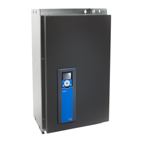
- Page 1 100 ® vacon 100 flow ® vacon 100 hvac ® ac drives installation manual wall-mounted drives...
-
Page 3: About This Manual
PREFACE VACON · 3 PREFACE Document ID: DPD01711G Date: 15.12.2015 ABOUT THIS MANUAL This manual is copyright of Vacon Plc. All Rights Reserved. 24-HOUR SUPPORT +358 (0)201 212 575 · EMAIL: VACON@VACON.COM... - Page 4 VACON · 4 TEL. +358 (0)201 2121 · FAX +358 (0)201 212 205...
-
Page 5: Table Of Contents
Wall mounting of MR7 4.2.5 Wall mounting of MR8, IP21 and IP54 4.2.6 Wall mounting of MR8, IP00 4.2.7 Wall mounting of MR9, IP21 and IP54 4.2.8 Wall mounting of MR9, IP00 24-HOUR SUPPORT +358 (0)201 212 575 · EMAIL: VACON@VACON.COM... - Page 6 VACON · 6 TABLE OF CONTENTS Dimensions for wall mounting, North America 4.3.1 Wall mounting of MR4, North America 4.3.2 Wall mounting of MR5, North America 4.3.3 Wall mounting of MR6, North America 4.3.4 Wall mounting of MR7, North America 4.3.5...
- Page 7 Mains voltage 208-240 V 10.1.2 Mains voltage 380-500 V 10.1.3 Overload capability 10.2 Vacon 100 HVAC - technical data ® 11 Technical data on control connections 11.1 Technical data on control connections 24-HOUR SUPPORT +358 (0)201 212 575 · EMAIL: VACON@VACON.COM...
-
Page 8: Approvals
VACON · 8 APPROVALS APPROVALS Here are the approvals that have been granted to this Vacon product. 1. EC Declaration of conformity Find the EC Declaration of Conformity on the next page. • 2. UL approval cULus approval file number E171278. - Page 9 Directive and the relevant standards. In Vaasa, 31st of March, 2015 Vesa Laisi President The year the CE marking was affixed: 2009 24-HOUR SUPPORT +358 (0)201 212 575 · EMAIL: VACON@VACON.COM...
-
Page 10: Safety
VACON · 10 SAFETY SAFETY THE SAFETY SYMBOLS USED IN THE MANUAL This manual contains warnings and cautions, which are identified with safety symbols. The warnings and cautions give important information on how to prevent injury and damage to the equipment or your system. -
Page 11: Caution
61800-5-1). See chapter 2.4 Grounding and earth fault protection. CAUTION! Do not use spare parts that are not from the manufacturer. Using other spare parts can cause damage to the drive. 24-HOUR SUPPORT +358 (0)201 212 575 · EMAIL: VACON@VACON.COM... -
Page 12: Grounding And Earth Fault Protection
VACON · 12 SAFETY CAUTION! Do not touch the components on the circuit boards. Static voltage can cause damage to these components. CAUTION! Make sure that the EMC level of the AC drive is correct for your mains. See chapter 7.6 Installation in an IT system. -
Page 13: Electro-Magnetic Compatibility (Emc)
(RCD) device, or a residual current-operated monitoring (RCM) device to give protection against a direct or an indirect contact. Use a type B RCD or RCM device on the mains side of the drive. 24-HOUR SUPPORT +358 (0)201 212 575 · EMAIL: VACON@VACON.COM... - Page 14 REMARQUE Vous pouvez télécharger les versions anglaise et française des manuels produit contenant l'en- semble des informations de sécurité, avertissements et mises en garde applicables sur le site www.vacon.com/ downloads. TEL. +358 (0)201 2121 · FAX +358 (0)201 212 205...
-
Page 15: Receiving The Delivery
See Chapter 3.2 Type designation code. PACKAGE LABEL Fig. 1: The package label of Vacon AC drives A. The batch ID F. The nominal output current B. The order number of Vacon G. -
Page 16: Type Designation Code
RECEIVING THE DELIVERY TYPE DESIGNATION CODE The type designation code of Vacon is made of standard codes and optional codes. Each part of the type designation code agrees to the data in your order. The code can have this format,... -
Page 17: Lifting The Frames Mr8 And Mr9
Remove the drive from the pallet where it was bolted to. Use a lifting device that is sufficiently strong for the weight of the drive. Put the lifting hooks symmetrically in a minimum of 2 holes. 24-HOUR SUPPORT +358 (0)201 212 575 · EMAIL: VACON@VACON.COM... -
Page 18: Accessories
VACON · 18 RECEIVING THE DELIVERY The maximum lifting angle is 45 degrees. ≤45° ACCESSORIES After you open the package and lift the drive out, make sure that you received all the accessories. The content of the accessories bag is different for the different frames and protection classes. -
Page 19: Frame Mr4
IP21: Cable grommet, hole diameter 25.3 mm Sealing for the cables IP54: Cable grommet, hole diameter 25.3 mm Sealing for the cables Cable grommet, hole diameter 33.0 mm Sealing for the cables 24-HOUR SUPPORT +358 (0)201 212 575 · EMAIL: VACON@VACON.COM... -
Page 20: Frame Mr6
IP54: Cable grommet, hole diameter 25.3 mm Sealing for the cables NOTE! The Vacon 100 FLOW and HVAC software do not have the dynamic braking or the ® brake resistor functions. TEL. +358 (0)201 2121 · FAX +358 (0)201 212 205... -
Page 21: Frame Mr7
To prevent contact between cables Cable grommet, hole diameter 25.3 mm Sealing for the cables IP00: Touch protection shield To prevent contact with live parts IP00: M4x8 screw To attach the touch protection shield 24-HOUR SUPPORT +358 (0)201 212 575 · EMAIL: VACON@VACON.COM... -
Page 22: Frame Mr9
VACON · 22 RECEIVING THE DELIVERY 3.5.6 FRAME MR9 Table 10: The content of the accessories bag Item Quantity Description M4x16 screw Screws for the grounding clamps for control cable Grounding clamp for control cable Control cable grounding Grounding clamp for cable shield KP40... -
Page 23: Mounting
8 Technical data, Vacon® 100 or 9 Technical data, Vacon® 100 FLOW are not available. Install the AC drive with the screws and other components that you received in the delivery. -
Page 24: Wall Mounting Of Mr5
A. Use these mounting holes when you replace your Vacon NX AC drive with a ® Vacon 100, Vacon 100 FLOW or ® ® Vacon 100 HVAC AC drive. ® TEL. +358 (0)201 2121 · FAX +358 (0)201 212 205... -
Page 25: Wall Mounting Of Mr6
MOUNTING VACON · 25 4.2.3 WALL MOUNTING OF MR6 IP21 Ø9 Ø15.5 Ø40 Ø33 Ø40 IP54 Ø25 Ø9 Fig. 4: The dimensions of the AC drive, MR6 [mm] 24-HOUR SUPPORT +358 (0)201 212 575 · EMAIL: VACON@VACON.COM... -
Page 26: Wall Mounting Of Mr7
VACON · 26 MOUNTING 4.2.4 WALL MOUNTING OF MR7 Ø9 IP21 Ø20 Ø16 Ø51 IP54 Ø25 Ø50 Fig. 5: The dimensions of the AC drive, MR7 [mm] TEL. +358 (0)201 2121 · FAX +358 (0)201 212 205... -
Page 27: Wall Mounting Of Mr8, Ip21 And Ip54
MOUNTING VACON · 27 4.2.5 WALL MOUNTING OF MR8, IP21 AND IP54 Ø25 Ø60 Ø9 Ø11 Ø9 Ø22 Fig. 6: The dimensions of the AC drive, MR8, IP21 and IP54 [mm] 24-HOUR SUPPORT +358 (0)201 212 575 · EMAIL: VACON@VACON.COM... -
Page 28: Wall Mounting Of Mr8, Ip00
VACON · 28 MOUNTING 4.2.6 WALL MOUNTING OF MR8, IP00 Ø9 10.8 Ø11 Ø9 Ø22 15.1 Fig. 7: The dimensions of the AC drive, MR8, IP00 [mm] A. An optional main connector cover for the cabinet installation TEL. +358 (0)201 2121 · FAX +358 (0)201 212 205... -
Page 29: Wall Mounting Of Mr9, Ip21 And Ip54
WALL MOUNTING OF MR9, IP21 AND IP54 Ø59 Ø25 Ø9 Ø9 27,5 Ø22 M8 GND Ø9 1122 Ø9 1150 Fig. 8: The dimensions of the AC drive, MR9, IP21 and IP54 [mm] 24-HOUR SUPPORT +358 (0)201 212 575 · EMAIL: VACON@VACON.COM... -
Page 30: Wall Mounting Of Mr9, Ip00
VACON · 30 MOUNTING 4.2.8 WALL MOUNTING OF MR9, IP00 Ø9 Ø9 16.5 840.5 Ø22 Ø25 Fig. 9: The dimensions of the AC drive, MR9, IP00 [mm] A. An optional main connector cover for the cabinet installation TEL. +358 (0)201 2121 · FAX +358 (0)201 212 205... -
Page 31: Dimensions For Wall Mounting, North America
4.3.1 WALL MOUNTING OF MR4, NORTH AMERICA 5.04 Ø0.28 7.48 3.94 UL Type 1 Ø0.51 Ø0.98 UL Type 12 Ø0.98 3.94 Fig. 10: The dimensions of the AC drive, MR4 [in] 24-HOUR SUPPORT +358 (0)201 212 575 · EMAIL: VACON@VACON.COM... -
Page 32: Wall Mounting Of Mr5, North America
A. Use these mounting holes when you replace your Vacon NX AC drive with a ® Vacon 100, Vacon 100 FLOW or ® ® Vacon 100 HVAC AC drive. ® TEL. +358 (0)201 2121 · FAX +358 (0)201 212 205... -
Page 33: Wall Mounting Of Mr6, North America
WALL MOUNTING OF MR6, NORTH AMERICA 7.68 UL Type 1 Ø0.35 9.02 5.83 Ø0.61 Ø1.57 Ø1.30 Ø1.57 UL Type 12 Ø0.98 5.83 Ø0.35 Fig. 12: The dimensions of the AC drive, MR6 [in] 24-HOUR SUPPORT +358 (0)201 212 575 · EMAIL: VACON@VACON.COM... -
Page 34: Wall Mounting Of Mr7, North America
VACON · 34 MOUNTING 4.3.4 WALL MOUNTING OF MR7, NORTH AMERICA 9.33 10.20 Ø0.35 UL Type 1 7.48 Ø0.79 Ø0.63 Ø2.01 UL Type 12 Ø0.98 Ø1.97 Fig. 13: The dimensions of the AC drive, MR7 [in] TEL. +358 (0)201 2121 · FAX +358 (0)201 212 205... -
Page 35: Wall Mounting Of Mr8, North America
VACON · 35 4.3.5 WALL MOUNTING OF MR8, NORTH AMERICA 4.61 7.40 Ø0.98 Ø2.36 0.35 0.87 26.10 10.31 Ø0.35 Ø0.43 Ø0.35 Ø0.87 39.21 Fig. 14: The dimensions of the AC drive, MR8 [in] 24-HOUR SUPPORT +358 (0)201 212 575 · EMAIL: VACON@VACON.COM... -
Page 36: Wall Mounting Of Mr8, Ul Open Type, North America
VACON · 36 MOUNTING 4.3.6 WALL MOUNTING OF MR8, UL OPEN TYPE, NORTH AMERICA 0.37 26.10 Ø0.35 0.43 Ø0.43 Ø0.35 Ø0.87 0.71 0.59 26.89 31.26 Fig. 15: The dimensions of the AC drive, MR8, UL Open Type [in] A. An optional main connector cover for the cabinet installation TEL. -
Page 37: Wall Mounting Of Mr9, North America
WALL MOUNTING OF MR9, NORTH AMERICA Ø2.32 6.54 Ø0.98 12.52 Ø0.35 31.89 11.18 1.08 Ø0.87 M8 GND Ø0.35 44.17 Ø0.35 0.55 45.28 Fig. 16: The dimensions of the AC drive, MR9 [in] 24-HOUR SUPPORT +358 (0)201 212 575 · EMAIL: VACON@VACON.COM... -
Page 38: Wall Mounting Of Mr9, Ul Open Type, North America
VACON · 38 MOUNTING 4.3.8 WALL MOUNTING OF MR9, UL OPEN TYPE, NORTH AMERICA 1.97 Ø0.35 Ø0.35 31.89 0.65 0.55 33.09 5.12 Ø0.87 2.56 12.52 Fig. 17: The dimensions of the AC drive, MR9, UL Open Type [in] A. An optional main connector cover for the... - Page 39 Fig. 18: Example of flange mounting (frame MR9) A. The cabinet wall or other surface D. IP00 / UL Open Type B. The front E. IP54 / UL Type 12 C. The rear 24-HOUR SUPPORT +358 (0)201 212 575 · EMAIL: VACON@VACON.COM...
- Page 40 VACON · 40 MOUNTING Fig. 19: The dimensions of the opening and drive outline with flange A. The height of the opening for the flange E. The distance between the bottom of the mounting drive and the bottom of the opening B.
- Page 41 38.4 19.1 Fig. 20: Sealing of the opening for MR8 and MR9 A. The AC drive C. Gasket tape B. The outline of the opening D. The top of the drive 24-HOUR SUPPORT +358 (0)201 212 575 · EMAIL: VACON@VACON.COM...
-
Page 42: Flange Mounting Of Mr4
VACON · 42 MOUNTING 4.4.1 FLANGE MOUNTING OF MR4 Ø7 Fig. 21: The dimensions of the AC drive, flange mounting, MR4 [mm] TEL. +358 (0)201 2121 · FAX +358 (0)201 212 205... -
Page 43: Flange Mounting Of Mr5
MOUNTING VACON · 43 4.4.2 FLANGE MOUNTING OF MR5 11.5 Fig. 22: The dimensions of the AC drive, flange mounting, MR5 [mm] 24-HOUR SUPPORT +358 (0)201 212 575 · EMAIL: VACON@VACON.COM... -
Page 44: Flange Mounting Of Mr6
VACON · 44 MOUNTING 4.4.3 FLANGE MOUNTING OF MR6 115.5 Fig. 23: The dimensions of the AC drive, flange mounting, MR6 [mm] TEL. +358 (0)201 2121 · FAX +358 (0)201 212 205... -
Page 45: Flange Mounting Of Mr7
MOUNTING VACON · 45 4.4.4 FLANGE MOUNTING OF MR7 110.4 148.8 Fig. 24: The dimensions of the AC drive, flange mounting, MR7 [mm] 24-HOUR SUPPORT +358 (0)201 212 575 · EMAIL: VACON@VACON.COM... -
Page 46: Flange Mounting Of Mr8
VACON · 46 MOUNTING 4.4.5 FLANGE MOUNTING OF MR8 19.4 89.6 82.5 852.6 890.8 831.5 573.5 315.5 424.7 GND M8 109.5 Fig. 25: The dimensions of the AC drive, flange mounting, MR8 [mm] TEL. +358 (0)201 2121 · FAX +358 (0)201 212 205... -
Page 47: Flange Mounting Of Mr9
MOUNTING VACON · 47 4.4.6 FLANGE MOUNTING OF MR9 1039 10.5 10.5 397.5 1060 108.5 Fig. 26: The dimensions of the AC drive, flange mounting, MR9 [mm] 24-HOUR SUPPORT +358 (0)201 212 575 · EMAIL: VACON@VACON.COM... -
Page 48: Dimensions For Flange Mounting, North America
VACON · 48 MOUNTING DIMENSIONS FOR FLANGE MOUNTING, NORTH AMERICA 4.5.1 FLANGE MOUNTING OF MR4, NORTH AMERICA 5.98 4.80 Ø0.28 0.59 2.83 5.28 4.45 3.03 5.04 7.48 Fig. 27: The dimensions of the AC drive, flange mounting, MR4 [in] TEL. +358 (0)201 2121 · FAX +358 (0)201 212 205... -
Page 49: Flange Mounting Of Mr5, North America
VACON · 49 4.5.2 FLANGE MOUNTING OF MR5, NORTH AMERICA 5.71 0.45 2.83 5.71 0.47 3.94 4.49 6.65 8.43 5.67 5.91 Fig. 28: The dimensions of the AC drive, flange mounting, MR5 [in] 24-HOUR SUPPORT +358 (0)201 212 575 · EMAIL: VACON@VACON.COM... -
Page 50: Flange Mounting Of Mr6, North America
VACON · 50 MOUNTING 4.5.3 FLANGE MOUNTING OF MR6, NORTH AMERICA 4.55 0.47 7.72 2.83 0.24 0.71 7.24 4.17 4.84 8.66 9.13 9.02 7.91 7.68 Fig. 29: The dimensions of the AC drive, flange mounting, MR6 [in] TEL. +358 (0)201 2121 · FAX +358 (0)201 212 205... -
Page 51: Flange Mounting Of Mr7, North America
MOUNTING VACON · 51 4.5.4 FLANGE MOUNTING OF MR7, NORTH AMERICA 11.26 10.67 9.33 0.30 2.83 4.35 5.86 9.06 Fig. 30: The dimensions of the AC drive, flange mounting, MR7 [in] 24-HOUR SUPPORT +358 (0)201 212 575 · EMAIL: VACON@VACON.COM... -
Page 52: Flange Mounting Of Mr8, North America
VACON · 52 MOUNTING 4.5.5 FLANGE MOUNTING OF MR8, NORTH AMERICA 1.02 0.76 3.53 3.25 33.57 35.07 32.74 22.58 12.42 0.27 4.02 16.72 0.07 35.35 GND M8 4.31 Fig. 31: The dimensions of the AC drive, flange mounting, MR8 [in]... -
Page 53: Flange Mounting Of Mr9, North America
FLANGE MOUNTING OF MR9, NORTH AMERICA 6.42 2.20 40.90 3.35 2.95 11.81 11.81 0.41 0.41 4.02 15.65 41.73 4.27 8.27 Fig. 32: The dimensions of the AC drive, flange mounting, MR9 [in] 24-HOUR SUPPORT +358 (0)201 212 575 · EMAIL: VACON@VACON.COM... -
Page 54: Cooling
VACON · 54 MOUNTING COOLING The AC drive produces heat in operation. The fan circulates air and decreases the temperature of the drive. Make sure that there is sufficiently free space around the drive. Some free space is also necessary for maintenance. - Page 55 * = For a drive with IP54 / UL Type 12, the minimum clearances A and B are 0 mm / 0 in. Table 14: The necessary quantity of cooling air Frame The quantity of cooling The quantity of cooling air [m air [CFM] 26.5 44.1 111.8 108.9 197.2 365.5 24-HOUR SUPPORT +358 (0)201 212 575 · EMAIL: VACON@VACON.COM...
- Page 56 VACON · 56 MOUNTING Fig. 34: The installation space when drives are installed on top of each other If you install many drives above each other 1. The necessary free space is C + D. 2. Make the outlet air of the lower unit go away from the air intake of the upper unit. To do this, attach a metal plate to the cabinet wall between the drives.
-
Page 57: Power Cabling
Table 15: The selection of the correct cable Cable type EMC requirements environment environment Category C2 Category C3 Category C4 The mains cable The motor cable The control cable 24-HOUR SUPPORT +358 (0)201 212 575 · EMAIL: VACON@VACON.COM... -
Page 58: Ul Standards On Cabling
60 or 75 °C (140 or 167 °F). You can use the drive on a circuit that gives a maximum of 100 000 rms symmetrical amperes, and a maximum of 600 V, when the drive is protected by Class T and J fuses. - Page 59 In the selection of cables, refer to local regulations, cable installation conditions and cable specification. NOTE! The Vacon 100 FLOW and HVAC software does not have the dynamic braking or ® the brake resistor functions. 24-HOUR SUPPORT +358 (0)201 212 575 · EMAIL: VACON@VACON.COM...
- Page 60 VACON · 60 POWER CABLING Table 16: The cable and fuse sizes for Vacon 100, mains voltage 208-240 V and 380-500 V ® Frame Type IL [A] Fuse Mains, motor and Terminal cable size (gG/gL) brake resistor* cable Cu [mm...
- Page 61 * = If you use a multi-conductor cable, 1 of the conductors of the brake resistor cable stays unconnected. It is also possible to use a single cable if you obey the minimum cross- sectional area of the cable. 24-HOUR SUPPORT +358 (0)201 212 575 · EMAIL: VACON@VACON.COM...
- Page 62 VACON · 62 POWER CABLING Table 17: The cable and fuse sizes for Vacon 100, mains voltage 525-690 V ® Frame Type IL [A] Fuse Mains, motor and Terminal cable size (gG/gL) brake resistor* cable Cu [mm Mains cable Grounding...
-
Page 63: Cable And Fuse Sizes, North America
POWER CABLING VACON · 63 Table 17: The cable and fuse sizes for Vacon 100, mains voltage 525-690 V ® Frame Type IL [A] Fuse Mains, motor and Terminal cable size (gG/gL) brake resistor* cable Cu [mm Mains cable Grounding... - Page 64 VACON · 64 POWER CABLING NOTE! The Vacon 100 FLOW and HVAC software do not have the dynamic braking or the ® brake resistor functions. TEL. +358 (0)201 2121 · FAX +358 (0)201 212 205...
- Page 65 POWER CABLING VACON · 65 Table 18: The cable and fuse sizes for Vacon 100 in North America, mains voltage 208-240 V ® and 380-500 V Frame Type IL [A] Fuse Mains, motor and Terminal cable size (Class brake resistor*...
- Page 66 VACON · 66 POWER CABLING Table 18: The cable and fuse sizes for Vacon 100 in North America, mains voltage 208-240 V ® and 380-500 V Frame Type IL [A] Fuse Mains, motor and Terminal cable size (Class brake resistor*...
- Page 67 POWER CABLING VACON · 67 Table 19: The cable and fuse sizes for Vacon 100 in North America, mains voltage 525-690 V ® Frame Type IL [A] Fuse Mains, motor Terminal cable size (Class T/J) and brake resistor* Mains cable...
-
Page 68: Brake Resistor Cables
Laboratories UL 61800-5-1. BRAKE RESISTOR CABLES Vacon 100 AC drives have terminals for an optional external brake resistor. These ® terminals are identified with R+ and R- (in MR4 and MR5) or DC+/R+ and R- (in MR6, MR7, MR8 and MR9). You can find the dimensions that we recommend for the brake resistor cables in the tables in chapters 5.3.1 Cable and fuse sizes and 5.3.2 Cable and fuse sizes, North... -
Page 69: Preparing For The Cable Installation
The distances are also valid between the motor cables and the signal cables of other • systems. The maximum lengths of shielded motor cables are 100 m / 328 ft (for MR4), 150 m / 492 • ft (for MR5 and MR6), and 200 m / 656 ft (for MR7, MR8, and MR9). - Page 70 * = As short as possible. Strip the motor cable, the mains cable, and the brake resistor cable. NOTE! The Vacon 100 FLOW and HVAC software ® do not have the dynamic braking or the brake resistor functions. MAINS MOTOR G.
- Page 71 M4x8 Put the grommets in the openings of the cable entry plate. These parts are included in the package. The picture shows the grommets in IP21 in the EU version. 24-HOUR SUPPORT +358 (0)201 212 575 · EMAIL: VACON@VACON.COM...
- Page 72 VACON · 72 POWER CABLING Put the cables - the mains cable, the motor cable and the optional brake cable - in the openings of the cable entry plate. a) Cut the grommets open to move the cables through them. If the grommets fold in when you put the cable, pull the cable back to make the grommets straight.
- Page 73 B. The terminals e) See the correct tightening torques in Table 23. C. The grounding terminal D. The mains cable E. The brake resistor cable F. The motor cable 24-HOUR SUPPORT +358 (0)201 212 575 · EMAIL: VACON@VACON.COM...
- Page 74 VACON · 74 POWER CABLING Make sure that the grounding conductor is connected to the motor and also to the terminals that are identified with a) To obey the requirements of the standard EN 61800-5-1, obey the instructions in chapter 2.4 Grounding and earth fault protection.
- Page 75 * = The tightening torque for a torx screw. ** = The tightening torque for an Allen screw. Fig. 37: The tightening torque for the Allen screw in MR7 is 5.6 Nm 24-HOUR SUPPORT +358 (0)201 212 575 · EMAIL: VACON@VACON.COM...
-
Page 76: Frames Mr8 To Mr9
* = As short as possible. Strip the motor cable, the mains cable, and the brake resistor cable. NOTE! The Vacon 100 FLOW and HVAC software ® do not have the dynamic braking or the brake resistor functions. MAINS MOTOR G. - Page 77 POWER CABLING VACON · 77 MR9 only: Open the cover of the AC drive. M4x10 24-HOUR SUPPORT +358 (0)201 212 575 · EMAIL: VACON@VACON.COM...
- Page 78 VACON · 78 POWER CABLING Remove the cable cover. M4x8 M4x8 TEL. +358 (0)201 2121 · FAX +358 (0)201 212 205...
- Page 79 POWER CABLING VACON · 79 Remove the cable entry plate. M4x8 M5x10 24-HOUR SUPPORT +358 (0)201 212 575 · EMAIL: VACON@VACON.COM...
- Page 80 VACON · 80 POWER CABLING MR9 only: Loosen the screws and remove the M4x8 sealing plate. TEL. +358 (0)201 2121 · FAX +358 (0)201 212 205...
- Page 81 POWER CABLING VACON · 81 Remove the EMC shield plate. M4x8 A. The wing nut in MR8 24-HOUR SUPPORT +358 (0)201 212 575 · EMAIL: VACON@VACON.COM...
- Page 82 VACON · 82 POWER CABLING Find the motor cable terminals. The location of the terminals is different than usually, especially in R+ R- L2 L3 DC- MR8. R+ R- L2 L3 DC- TEL. +358 (0)201 2121 · FAX +358 (0)201 212 205...
- Page 83 Pull the first bit of the cable out of the grommet so that it stays straight. b) If this is not possible, make the connection tight with some insulation tape or a cable tie. 24-HOUR SUPPORT +358 (0)201 212 575 · EMAIL: VACON@VACON.COM...
- Page 84 VACON · 84 POWER CABLING If you use thick cables, put the cable insulators in between the terminals to prevent contact between the cables. TEL. +358 (0)201 2121 · FAX +358 (0)201 212 205...
- Page 85 See chapter 2.4 Grounding and earth fault protection. d) See the correct tightening torques in Table 26. A. Connection of the cables B. Make a grounding connection in MR8 A. Make a grounding connection in MR9 24-HOUR SUPPORT +358 (0)201 212 575 · EMAIL: VACON@VACON.COM...
- Page 86 VACON · 86 POWER CABLING If you use many cables on one connector, put the cable lugs on top of each other. A. The first cable lug B. The second cable lug C. The connector Expose the shield of all 3 cables to make a 360- degree connection with the grounding clamp for cable shield.
- Page 87 61800-5-1, obey the instructions in chapter 2.4 Grounding and earth fault protection. b) Connect the protective conductor to 1 of the screw connectors with a cable shoe and an M8 screw. 24-HOUR SUPPORT +358 (0)201 212 575 · EMAIL: VACON@VACON.COM...
-
Page 88: Installation In A Corner-Grounded Network
VACON · 88 POWER CABLING Table 26: Tightening torques of the terminals Tightening torque: Tightening torque: Tightening torque: the mains cable and the grounding clamps the grounding clamps Frame Type motor cable terminals for cable shield for grounding conductor [Nm] lb-in. -
Page 89: Control Unit
2 relay outputs and a G. A DIP switch for the isolation of the thermistor digital inputs from ground D. The option boards H. A DIP switch for the signal selection of Analogue Input 2 24-HOUR SUPPORT +358 (0)201 212 575 · EMAIL: VACON@VACON.COM... -
Page 90: Control Unit Cabling
VACON · 90 CONTROL UNIT A DIP switch for the signal selection of K. A fan (only in IP54 of MR4 and of MR5) Analogue Input 1 L. The battery for the RTC J. The status indicator of the Ethernet M. -
Page 91: Control Terminals And Dip Switches
For more information, see 11.1 Technical data on control connections. Some terminals are assigned for signals that have optional functions that you can use with the DIP switches. See more in 6.2.2.1 Selection of terminal functions with DIP switches. 24-HOUR SUPPORT +358 (0)201 212 575 · EMAIL: VACON@VACON.COM... - Page 92 VACON · 92 CONTROL UNIT Standard I/O board Signal Terminal Description +10 Vref Reference output Reference potentiometer 1...10kΩ Analogue input, AI1+ voltage or current Frequency reference Analogue input AI1- 2-wire transmitter common, (current) Actual value Analogue input, AI2+ voltage or current...
- Page 93 You can make 2 selections with the DIP switches for specified terminals. The switches have 2 positions: up and down. You can see the location of the DIP switches and the possible selections in Fig. 42. 24-HOUR SUPPORT +358 (0)201 212 575 · EMAIL: VACON@VACON.COM...
- Page 94 VACON · 94 CONTROL UNIT RS-485 Fig. 42: The selections of the DIP switches A. The voltage signal (U), 0-10 V input D. ON B. The current signal (I), 0-20 mA input E. The RS-485 bus termination C. OFF Table 29: The default positions of the DIP switches...
-
Page 95: Fieldbus Connection
A and B of the standard I/O board. If you use an Ethernet cable, connect it to the Ethernet terminal below the cover of the drive. 24-HOUR SUPPORT +358 (0)201 212 575 · EMAIL: VACON@VACON.COM... -
Page 96: Using Fieldbus Through An Ethernet Cable
A shielded RJ45 plug, maximum length 40 mm (1.57 in) The cable type CAT5e STP The cable length Maximum 100 m (328 ft) ETHERNET CABLING Connect the Ethernet cable to its terminal. TEL. +358 (0)201 2121 · FAX +358 (0)201 212 205... - Page 97 Pull the first bit of the cable out of the grommet so that it stays straight. If this is not possible, make the connection tight with some insulation tape or a cable tie. IP21 IP54 24-HOUR SUPPORT +358 (0)201 212 575 · EMAIL: VACON@VACON.COM...
- Page 98 VACON · 98 CONTROL UNIT Put the cover of the drive back. Keep the distance between the Ethernet cable and the motor cable at a minimum of 30 cm (11.81 in). A. The Ethernet cable in IP21 A. The Ethernet cable in IP54 See more in the Installation Manual of the fieldbus that you have.
-
Page 99: Using Fieldbus Through An Rs485 Cable
Strip the cable at a maximum length of 15 mm (0.59 in). Do not remove the aluminium shield of the cable. 24-HOUR SUPPORT +358 (0)201 212 575 · EMAIL: VACON@VACON.COM... - Page 100 VACON · 100 CONTROL UNIT Connect the cable to the standard I/O board of the drive, in terminals A and B. A = negative • B = positive • Attach the shield of the cable to the frame of the drive with a grounding clamp for control cable to make a grounding connection.
- Page 101 Biasing is built in the bus termination resistor. The termination resistance is 220 Ω. In IP21, unless you have cut the openings for other cables, cut an opening on the cover of the drive for the RS485 cable. 24-HOUR SUPPORT +358 (0)201 212 575 · EMAIL: VACON@VACON.COM...
- Page 102 VACON · 102 CONTROL UNIT Put the cover of the drive back. Pull the RS485 cables to the side. a) Keep the distance of the Ethernet, I/O and Fieldbus cables from the motor cable at a minimum of 30 cm (11.81 in).
-
Page 103: Installation Of Option Boards
The Profibus DPV1 fieldbus board D, E OPTE5 The Profibus DPV1 fieldbus board D, E (with a type D connector) OPTE6 The CanOpen fieldbus board D, E OPTE7 The DeviceNet fieldbus board D, E 24-HOUR SUPPORT +358 (0)201 212 575 · EMAIL: VACON@VACON.COM... -
Page 104: The Installation Procedure
VACON · 104 CONTROL UNIT THE INSTALLATION PROCEDURE Open the cover of the AC drive. WARNING! Do not touch the control terminals. They M4x55 can have a dangerous voltage also when the drive is disconnected from mains. If you have an OPTB or an OPTC option board, make sure that the label on it says "dv"... -
Page 105: Installation Of A Battery For The Real Time Clock (Rtc)
The digital inputs on the standard I/O board can be galvanically isolated from the I/O ground. To isolate the digital inputs, use the DIP switch that has the positions FLOAT and GND. 24-HOUR SUPPORT +358 (0)201 212 575 · EMAIL: VACON@VACON.COM... - Page 106 VACON · 106 CONTROL UNIT 10Vref +24V AI1+ AI1- AI2+ AI2- DI1... AO1+ AO1- +24Vin RS485 RO1/1 RO1/2 RO1/3 RO2/1 RO2/2 RO2/3 TI1+ TI1- DC+/R+ Fig. 45: The galvanic isolation barriers A. The control unit B. The power unit TEL. +358 (0)201 2121 · FAX +358 (0)201 212 205...
-
Page 107: Commissioning And Additional Instructions
The connections of the AC drive are live when the drive is connected to mains. COMMISSIONING OF THE DRIVE Read the safety instructions in chapters 2 Safety and 7.1 Commissioning safety and obey them. 24-HOUR SUPPORT +358 (0)201 212 575 · EMAIL: VACON@VACON.COM... -
Page 108: Operation Of The Motor
VACON · 108 COMMISSIONING AND ADDITIONAL INSTRUCTIONS After the installation: Make sure that the motor is installed correctly. • Make sure that the motor terminals are not connected to mains. • Make sure that the AC drive and the motor are grounded. -
Page 109: Installation In A Marine Environment
Change the EMC protection of the AC drive to level C4. Open the cover of the AC drive. In MR4 and MR5, to find the EMC jumpers, remove the cable cover. 24-HOUR SUPPORT +358 (0)201 212 575 · EMAIL: VACON@VACON.COM... - Page 110 VACON · 110 COMMISSIONING AND ADDITIONAL INSTRUCTIONS Find the EMC jumpers that connect the RFI filters to ground. TEL. +358 (0)201 2121 · FAX +358 (0)201 212 205...
- Page 111 COMMISSIONING AND ADDITIONAL INSTRUCTIONS VACON · 111 200-500 V 600/690 V To disconnect the RFI filters from ground, remove the EMC jumpers. Pull the EMC jumper out with the tool. 24-HOUR SUPPORT +358 (0)201 212 575 · EMAIL: VACON@VACON.COM...
-
Page 112: The Emc Jumper In Mr7
VACON · 112 COMMISSIONING AND ADDITIONAL INSTRUCTIONS After the change, write "The EMC level was changed" and the date on the "product modified" Product modified label. If the label is not attached at this time, attach Date: Date: it on the drive near the name plate. - Page 113 If the label is not attached at this time, attach Date: Date: it on the drive near the name plate. Date: HOW TO FIND THE EMC JUMPERS, 600/690 V Open the cover of the AC drive. Remove the terminal cover. 24-HOUR SUPPORT +358 (0)201 212 575 · EMAIL: VACON@VACON.COM...
-
Page 114: The Emc Jumper In Mr8
VACON · 114 COMMISSIONING AND ADDITIONAL INSTRUCTIONS Remove the EMC jumper. After the change, write "The EMC level was changed" and the date on the "product modified" Product modified label. If the label is not attached at this time, attach... -
Page 115: The Emc Jumper In Mr9
HOW TO FIND THE EMC JUMPER 1 Open the cover of the AC drive. Remove the cover of the fan. In IP54, also remove the fan. 24-HOUR SUPPORT +358 (0)201 212 575 · EMAIL: VACON@VACON.COM... -
Page 116: Maintenance
VACON · 116 COMMISSIONING AND ADDITIONAL INSTRUCTIONS Find the place of the jumper behind the fan. If you change the EMC level, write "The EMC level was changed" and the date on the "product Product modified Date: modified" label. If the label is not attached at this Date: time, attach it on the drive near the name plate. - Page 117 24 months (The interval is different in different envi- ronments.) Clean the heatsink and the cooling tunnel. 3-6 years In IP54, change the internal fan. 6-10 years Change the main fan. 10 years Replace the battery of the RTC. 24-HOUR SUPPORT +358 (0)201 212 575 · EMAIL: VACON@VACON.COM...
-
Page 118: Technical Data, Vacon
TECHNICAL DATA, VACON® 100 TECHNICAL DATA, VACON ® AC DRIVE POWER RATINGS 8.1.1 MAINS VOLTAGE 208-240 V Table 34: The power ratings of Vacon 100 in mains voltage 208-240 V, 50-60 Hz, 3~ ® Frame Drive Loadability Motor shaft power type... - Page 119 VACON · 119 * = See chapter 8.1.5 Overload capability. NOTE! The currents in given ambient temperatures (in chapter 8.2 Vacon® 100 - technical data) are achieved only when the switching frequency is equal to or less than the factory default.
-
Page 120: Mains Voltage 380-500 V
VACON · 120 TECHNICAL DATA, VACON® 100 8.1.2 MAINS VOLTAGE 380-500 V Table 35: The power ratings of Vacon 100 in mains voltage 380-500 V, 50-60 Hz, 3~ ® Frame Drive Loadability Motor shaft power type Low * High *... -
Page 121: Mains Voltage 525-600 V
TECHNICAL DATA, VACON® 100 VACON · 121 NOTE! The currents in given ambient temperatures (in chapter 8.2 Vacon® 100 - technical data) are achieved only when the switching frequency is equal to or less than the factory default. If your process includes a cyclical load, for example if there are lifts or winches, speak to the manufacturer to get the dimensioning information. -
Page 122: Mains Voltage 525-690 V
VACON · 122 TECHNICAL DATA, VACON® 100 8.1.4 MAINS VOLTAGE 525-690 V Table 37: The power ratings of Vacon 100 in mains voltage 525-690 V, 50-60 Hz, 3~ ® Frame Drive Loadability Motor shaft power type High 600 V 690 V... -
Page 123: Brake Resistor Ratings
For more information, refer to the standard IEC61800-2 (IEC:1998). 8.1.6 BRAKE RESISTOR RATINGS Make sure that the resistance is higher than the set minimum resistance. The power handling capacity must be sufficient for the application. 24-HOUR SUPPORT +358 (0)201 212 575 · EMAIL: VACON@VACON.COM... - Page 124 VACON · 124 TECHNICAL DATA, VACON® 100 Table 38: The recommended brake resistor types, mains voltage 208-240 V and 380-500 V Frame Duty cycle Type of brake resistor Resistance [Ω] Light duty BRR 0022 LD 5 63.0 Heavy duty BRR 0022 HD 5 63.0...
- Page 125 The heavy duty cycle is for brake resistor cyclic use (1 HD pulse in a 120-second period). • The heavy duty resistor is rated for a 3-second full power braking with a 7-second ramp to 0. 24-HOUR SUPPORT +358 (0)201 212 575 · EMAIL: VACON@VACON.COM...
- Page 126 VACON · 126 TECHNICAL DATA, VACON® 100 P [%] t [s] Fig. 48: The LD and HD pulses, P = brake power A. Light duty (LD) B. Heavy duty (HD) P [%] t [s] 3 5 10 123 125 130 Fig.
- Page 127 Table 43: The minimum resistance and the brake power, mains voltage 525-690 V Frame The minimum brake Brake power* @1166 VDC resistance [Ω] [kW] * = When you use recommended resistor types. 24-HOUR SUPPORT +358 (0)201 212 575 · EMAIL: VACON@VACON.COM...
-
Page 128: Vacon ® 100 - Technical Data
VACON · 128 TECHNICAL DATA, VACON® 100 VACON 100 - TECHNICAL DATA ® Table 44: The technical data of the Vacon 100 AC drive ® Technical item or function Technical data Input voltage U 208-240 V, 380-500 V, 525-600 V, 525-690 V, -10%…... - Page 129 Automatic switching frequency derating in case of overload. Frequency reference: Resolution 0.1% (10-bit), accuracy ±1% Resolution 0.01 Hz Analogue input • Panel reference • Field weakening point 8-320 Hz Acceleration time 0.1-3000 s Deceleration time 0.1-3000 s 24-HOUR SUPPORT +358 (0)201 212 575 · EMAIL: VACON@VACON.COM...
- Page 130 (IP21/UL Type 1 Models 3C2) IEC 60721-3-3, unit in operation, class 3S2 Ambient conditions • Altitude 100% nominal rating (no derating) up to 1000 m 1% derating for each 100m above 1000 m Maximum altitudes: 208-240 V: 4000 m (TN and IT systems) •...
- Page 131 Noise level MR5: 57-65 MR6: 63-72 MR7: 43-73 MR8: 58-73 MR9: 54-75 Safety standards and cer- EN 61800-5-1 (2007), CE, cUL (See the nameplate of tifications the drive for more approvals.) 24-HOUR SUPPORT +358 (0)201 212 575 · EMAIL: VACON@VACON.COM...
- Page 132 VACON · 132 TECHNICAL DATA, VACON® 100 Table 44: The technical data of the Vacon 100 AC drive ® Technical item or function Technical data Overvoltage trip limit Mains voltage 240 V: 456 VDC Mains voltage 500 V: 911 VDC...
-
Page 133: Technical Data, Vacon® 100 Flow
TECHNICAL DATA, VACON 100 FLOW ® AC DRIVE POWER RATINGS 9.1.1 MAINS VOLTAGE 208-240 V Table 45: The power ratings of Vacon 100 FLOW in mains voltage 208-240 V, 50-60 Hz, 3~ ® Frame Drive type Loadability * Motor shaft power Continuous... - Page 134 VACON · 134 TECHNICAL DATA, VACON® 100 FLOW NOTE! The currents in given ambient temperatures (in chapter 9.2 Vacon® 100 FLOW - technical data) are achieved only when the switching frequency is equal to or less than the factory default.
-
Page 135: Mains Voltage 380-500 V
TECHNICAL DATA, VACON® 100 FLOW VACON · 135 9.1.2 MAINS VOLTAGE 380-500 V Table 46: The power ratings of Vacon 100 FLOW in mains voltage 380-500 V, 50-60 Hz, 3~ ® Frame Drive type Loadability * Motor shaft power Continuous... -
Page 136: Mains Voltage 525-600 V
VACON · 136 TECHNICAL DATA, VACON® 100 FLOW NOTE! The currents in given ambient temperatures (in chapter 9.2 Vacon® 100 FLOW - technical data) are achieved only when the switching frequency is equal to or less than the factory default. -
Page 137: Mains Voltage 525-690 V
TECHNICAL DATA, VACON® 100 FLOW VACON · 137 9.1.4 MAINS VOLTAGE 525-690 V Table 48: The power ratings of Vacon 100 FLOW in mains voltage 525-690 V, 50-60 Hz, 3~ ® Frame Drive type Loadability Motor shaft power Continuous Input... - Page 138 VACON · 138 TECHNICAL DATA, VACON® 100 FLOW I L*110% I L*110% 1 min 9 min Fig. 50: Low overload in Vacon 100 FLOW ® For more information, refer to the standard IEC61800-2 (IEC:1998). TEL. +358 (0)201 2121 · FAX +358 (0)201 212 205...
-
Page 139: Vacon ® 100 Flow - Technical Data
< 100 kA. Output voltage Continuous output current : Ambient temperature max. +40 °C overload 1.1 x I (1 min/10 min) Motor connection Output frequency 0-320 Hz (standard) Frequency resolution 0.01 Hz 24-HOUR SUPPORT +358 (0)201 212 575 · EMAIL: VACON@VACON.COM... - Page 140 VACON · 140 TECHNICAL DATA, VACON® 100 FLOW Table 49: The technical data of the Vacon 100 FLOW AC drive ® Technical item or function Technical data Switching frequency (see 200-500 V parameter P3.1.2.3) MR4-MR6: • 1.5-10 kHz • Default: 6 kHz (except for 0012 2, 0031 2, •...
- Page 141 (IP21/UL Type 1 Models 3C2) IEC 60721-3-3, unit in operation, class 3S2 • Ambient conditions Altitude 100% nominal rating (no derating) up to 1000 m 1% derating for each 100m above 1000 m Maximum altitudes: 208-240 V: 4000 m (TN and IT systems) •...
- Page 142 VACON · 142 TECHNICAL DATA, VACON® 100 FLOW Table 49: The technical data of the Vacon 100 FLOW AC drive ® Technical item or function Technical data Vibration: 5-150 Hz Displacement amplitude 1 mm (peak) at 5-15.8 Hz EN 61800-5-1 •...
- Page 143 61800-5-1 requirements, you must use the system software version FW0072V007 or a newer version. If you use an older system software version, you must install a motor overtemperature protection to obey the UL regulations. 24-HOUR SUPPORT +358 (0)201 212 575 · EMAIL: VACON@VACON.COM...
-
Page 144: Technical Data, Vacon® 100 Hvac
TECHNICAL DATA, VACON® 100 HVAC 10.1 AC DRIVE POWER RATINGS 10.1.1 MAINS VOLTAGE 208-240 V Table 50: The power ratings of Vacon 100 HVAC in mains voltage 208-240 V, 50-60 Hz, 3~ ® Frame Drive type Loadability Motor shaft power... -
Page 145: Mains Voltage 380-500 V
TECHNICAL DATA, VACON® 100 HVAC VACON · 145 NOTE! The currents in given ambient temperatures (in chapter 10.2 Vacon® 100 HVAC - technical data) are achieved only when the switching frequency is equal to or less than the factory default. -
Page 146: Overload Capability
VACON · 146 TECHNICAL DATA, VACON® 100 HVAC NOTE! The currents in given ambient temperatures (in chapter 10.2 Vacon® 100 HVAC - technical data) are achieved only when the switching frequency is equal to or less than the factory default. -
Page 147: Vacon ® 100 Hvac - Technical Data
< 100 kA. Output voltage Continuous output current : Ambient temperature max. +40 °C overload 1.1 x I (1 min/10 min) Motor connection Output frequency 0-320 Hz (standard) Frequency resolution 0.01 Hz 24-HOUR SUPPORT +358 (0)201 212 575 · EMAIL: VACON@VACON.COM... - Page 148 VACON · 148 TECHNICAL DATA, VACON® 100 HVAC Table 52: The technical data of the Vacon 100 HVAC AC drive ® Technical item or function Technical data Switching frequency (see 200-500 V parameter P3.1.2.3) MR4-MR6: • 1.5-10 kHz • Default: 6 kHz (except for 0012 2, 0031 2, •...
- Page 149 • IEC 60721-3-3, unit in operation, class 3S2 • Ambient conditions Altitude 100% nominal rating (no derating) up to 1000 m 1% derating for each 100m above 1000 m Maximum altitudes: 208-240 V: 4000 m (TN and IT systems) •...
- Page 150 VACON · 150 TECHNICAL DATA, VACON® 100 HVAC Table 52: The technical data of the Vacon 100 HVAC AC drive ® Technical item or function Technical data Immunity Fulfils EN 61800-3 (2004), 1 and 2 environment Emissions 200-500 V: EN 61800-3 (2004), category C2.
- Page 151 61800-5-1 requirements, you must use the system software version FW0072V007 or a newer version. If you use an older system software version, you must install a motor overtemperature protection to obey the UL regulations. 24-HOUR SUPPORT +358 (0)201 212 575 · EMAIL: VACON@VACON.COM...
-
Page 152: Technical Data On Control Connections
Analogue input common (cur- Differential input if not connected to ground rent) Allows ±20 V common mode voltage to GND +24 V, ±10%, max volt. ripple < 100 mVrms 24 V aux. voltage max. 250 mA Short-circuit protected Ground for reference and controls (connected internally to I/O ground frame ground through 1 MΩ) - Page 153 Can be used as external power backup for the control unit RS485 Differential receiver/transmitter Set bus termination with dip switches (see chapter 6.2.2.1 Selection of terminal functions with DIP switches). Termination RS485 resistance = 220 Ω 24-HOUR SUPPORT +358 (0)201 212 575 · EMAIL: VACON@VACON.COM...
- Page 154 VACON · 154 TECHNICAL DATA ON CONTROL CONNECTIONS Table 54: The standard relay board (+SBF3) Terminal Signal Technical information Change-over contact (SPDT) relay. 5.5 mm isolation between channels. Switching capacity 24 VDC/8 A Relay output 1 * • 250 VAC/8 A •...
- Page 155 This is to prevent welding on the relay contacts. Refer to standard EN 60204-1, section 7.2.9. 24-HOUR SUPPORT +358 (0)201 212 575 · EMAIL: VACON@VACON.COM...
- Page 156 Document ID: Vacon Ltd Member of the Danfoss Group Rev. G Runsorintie 7 65380 Vaasa Sales code: DOC-INS100WM+DLUK Finland...
Need help?
Do you have a question about the 100 and is the answer not in the manual?
Questions and answers