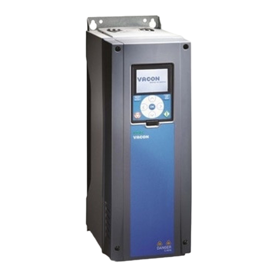
Vacon 100 industrial Installation Manual

Vacon 100 industrial Installation Manual

Enclosed ac drives
Hide thumbs Also See for 100 industrial:
Table of Contents

Advertisement

vacon 100 industrial
®
vacon 100 flow
®
ac drives
installation manual
enclosed drives

Advertisement

Table of Contents
loading

Summary of Contents for Vacon 100 industrial

  • Page 1 100 industrial ® vacon 100 flow ® ac drives installation manual enclosed drives...
  • Page 3: About This Manual

    Date: 11.11.2016 ABOUT THIS MANUAL This manual is copyright of Vacon Ltd. All Rights Reserved. The manual is subject to change without prior notice. The original language of these instructions is English. ABOUT THE PRODUCT This manual describes the VACON 100 Enclosed Drive.
  • Page 4 VACON · 4 LOCAL CONTACTS: HTTP://DRIVES.DANFOSS.COM/DANFOSS-DRIVES/LOCAL-CONTACTS/...
  • Page 5: Table Of Contents

    TABLE OF CONTENTS VACON · 5 TABLE OF CONTENTS Preface Document details About this manual About the product 1 Approvals 2 Safety The safety symbols used in the manual and the drive Warning Caution Grounding and earth fault protection Using an RCD or an RCM device...
  • Page 6 AC drive power ratings 8.1.1 Mains voltage 380-500 V 8.1.2 Mains voltage 525-690 V 8.1.3 Brake resistor ratings VACON 100 INDUSTRIAL - technical data ® 9 Technical data, VACON 100 FLOW ® AC drive power ratings 9.1.1 Mains voltage 380-500 V 9.1.2...
  • Page 7: Approvals

    APPROVALS VACON · 7 APPROVALS Here are the approvals that have been granted to this VACON product. ® 1. EC Declaration of conformity Find the EC Declaration of Conformity on the next page. • 2. UL approval * cULus approval file number E171278.
  • Page 8 Product(s) VACON® 100 AC drive IP00 Drives: Type(s) Wall-Mounted Drives: VACON® 0100 3L 0140 2...0310 2 VACON® 0100 3L 0003 2...0310 2 VACON® 0100 3L 0003 4...0310 4 VACON® 0100 3L 0140 5...1180 5 VACON® 0100 3L 0080 6...0820 6 VACON®...
  • Page 9: Safety

    SAFETY VACON · 9 SAFETY THE SAFETY SYMBOLS USED IN THE MANUAL AND THE DRIVE This manual contains warnings and cautions, which are identified with safety symbols. The warnings and cautions give important information on how to prevent injury and damage to the equipment or your system.
  • Page 10: Caution

    VACON · 10 SAFETY WARNING! Do not touch the motor cable terminals U, V, W, the brake resistor terminals or the DC terminals when the drive is connected to mains. These terminals are live when the drive is connected to mains, also when the motor does not operate.
  • Page 11: Grounding And Earth Fault Protection

    SAFETY VACON · 11 CAUTION! Make sure that there is reinforced protective ground connection. It is mandatory, because the touch current of the AC drives is more than 3.5 mA AC (refer to EN 61800-5-1). See chapter 2.4 Grounding and earth fault protection.
  • Page 12: Using An Rcd Or An Rcm Device

    VACON · 12 SAFETY The connection must be fixed. a) The protective grounding conductor must have a cross-sectional area of minimum 10 Cu or 16 mm Al. OR b) There must be an automatic disconnection of the mains, if the protective grounding conductor breaks.
  • Page 13 SAFETY VACON · 13 NOTE! You can download the English and French product manuals with applicable safety, warning and caution information from http://drives.danfoss.com/knowledge-center/technical-documentation/. REMARQUE Vous pouvez télécharger les versions anglaise et française des manuels produit contenant l'en- semble des informations de sécurité, avertissements et mises en garde applicables sur le site http:// drives.danfoss.com/knowledge-center/technical-documentation/.
  • Page 14: Receiving The Delivery

    2610011001 Marks: MSIP-REM-V93-VC100 VACON AB Made in Finland Danfoss A/S, 6430 Nordborg, Denmark Fig. 2: The package label of VACON AC drives ® A. The batch ID F. The nominal output current B. The order number G. The IP class C.
  • Page 15: Type Designation Code

    In chapter 4.5 The options you will find descriptions of the option codes. Table 3: The description of the parts in the type designation code Code Description VACON0100 The product family: VACON0100 = the VACON ® 100 product family Input/Function: 3L = A 3-phase input 0385 The drive rating in amperes.
  • Page 16: Removing The Packaging And Lifting The Ac Drive

    VACON · 16 RECEIVING THE DELIVERY If you keep the package in storage for more than 2 months, keep it in controlled conditions. Make sure that the temperature variation is small and that the humidity is less than 50%. REMOVING THE PACKAGING AND LIFTING THE AC DRIVE 3.5.1...
  • Page 17 RECEIVING THE DELIVERY VACON · 17 Use a hoist to move the drive. If you move more than 1 drive at a time, use rollers. LIFTING THE ENCLOSED DRIVE Remove the drive from the package. >60° Use a lifting device that is sufficiently strong for the weight of the drive.
  • Page 18: Product Modified" Label

    VACON · 18 RECEIVING THE DELIVERY CAUTION! To divide the weight of the AC drive equally, and to prevent damage to the equipment, always use 4 lifting holes. The minimum angle between the drive and the chain is 60 degrees.
  • Page 19: Disposal

    RECEIVING THE DELIVERY VACON · 19 DISPOSAL When the drive is at the end of its operation life, do not discard it as a part of municipal waste. You can recycle the primary components of the drive. You must disassemble some components before you can remove the different materials.
  • Page 20: Mounting

    VACON · 20 MOUNTING MOUNTING DIMENSIONS OF THE CABINET, IEC IEC = The product is qualified to the IEC criteria. NAM = The product is qualified to the UL criteria. The information on dimensions that you will need in cabling can be found in the order- specific documents.
  • Page 21 MOUNTING VACON · 21 Ø13 Ø13 Ø13 Fig. 4: The dimensions of the default cabinet, MR9 and MR10, [mm], IEC LOCAL CONTACTS: HTTP://DRIVES.DANFOSS.COM/DANFOSS-DRIVES/LOCAL-CONTACTS/...
  • Page 22: Dimensions Of The Cabinet With Additional Cabinet Sections, Iec

    VACON · 22 MOUNTING Ø 13 Ø 13 1135 Ø 13 1199 1206 Fig. 5: The dimensions of the default cabinet, MR12, [mm], IEC DIMENSIONS OF THE CABINET WITH ADDITIONAL CABINET SECTIONS, IEC IEC = The product is qualified to the IEC criteria.
  • Page 23 MOUNTING VACON · 23 NOTE! The height of the standard base plinth is 100 mm, but the height of the base plinth option (+CHPH) is 200 mm. LOCAL CONTACTS: HTTP://DRIVES.DANFOSS.COM/DANFOSS-DRIVES/LOCAL-CONTACTS/...
  • Page 24 VACON · 24 MOUNTING Ø13 Ø13 Fig. 6: The dimensions of the cabinet with the optional cabling from top, MR8, [mm], IEC LOCAL CONTACTS: HTTP://DRIVES.DANFOSS.COM/DANFOSS-DRIVES/LOCAL-CONTACTS/...
  • Page 25 MOUNTING VACON · 25 1135 Ø13 1199 Ø13 1155 Fig. 7: The dimensions of the cabinet with the optional cabling from top and the input contactor, MR10 with min 416 A, [mm], IEC. See Table 5. LOCAL CONTACTS: HTTP://DRIVES.DANFOSS.COM/DANFOSS-DRIVES/LOCAL-CONTACTS/...
  • Page 26 VACON · 26 MOUNTING 1735 Ø13 1799 1806 Ø13 Ø13 1755 Fig. 8: The dimensions of the cabinet with the optional cabling from top and/or the input contactor, MR12, [mm], IEC LOCAL CONTACTS: HTTP://DRIVES.DANFOSS.COM/DANFOSS-DRIVES/LOCAL-CONTACTS/...
  • Page 27: Dimensions Of The Cabinet, Nam

    MOUNTING VACON · 27 1135 Ø13 Ø13 1155 Fig. 9: The dimensions of the cabinet with the optional sine filter, MR10, [mm], IEC DIMENSIONS OF THE CABINET, NAM IEC = The product is qualified to the IEC criteria. NAM = The product is qualified to the UL criteria.
  • Page 28 VACON · 28 MOUNTING Ø13 Ø13 Ø13 639.5 Fig. 10: The dimensions of the default cabinet, MR8, [mm], NAM LOCAL CONTACTS: HTTP://DRIVES.DANFOSS.COM/DANFOSS-DRIVES/LOCAL-CONTACTS/...
  • Page 29 MOUNTING VACON · 29 Ø13 Ø13 Ø13 638.5 Fig. 11: The dimensions of the default cabinet, MR9 and MR10, [mm], NAM LOCAL CONTACTS: HTTP://DRIVES.DANFOSS.COM/DANFOSS-DRIVES/LOCAL-CONTACTS/...
  • Page 30: Dimensions Of The Cabinet, With Additional Cabinet Sections, Nam

    VACON · 30 MOUNTING Ø13 Ø13 1135 Ø13 1199 1206 Fig. 12: The dimensions of the default cabinet, MR12, [mm], NAM DIMENSIONS OF THE CABINET, WITH ADDITIONAL CABINET SECTIONS, IEC = The product is qualified to the IEC criteria. NAM = The product is qualified to the UL criteria.
  • Page 31 MOUNTING VACON · 31 Ø13 662.3 Ø13 Fig. 13: The dimensions of the cabinet with the optional cabling from top, MR8, [mm], NAM A. 3 x conduit hole Ø 22 mm LOCAL CONTACTS: HTTP://DRIVES.DANFOSS.COM/DANFOSS-DRIVES/LOCAL-CONTACTS/...
  • Page 32 VACON · 32 MOUNTING 935.9 Ø13 1000 1007 Ø13 648.9 Fig. 14: The dimensions of the cabinet with the optional cabling from top, MR10 with min 416 A, [mm], NAM A. 3 x conduit hole Ø 22 mm LOCAL CONTACTS: HTTP://DRIVES.DANFOSS.COM/DANFOSS-DRIVES/LOCAL-CONTACTS/...
  • Page 33 MOUNTING VACON · 33 1735 Ø13 1799 676.5 1807 Ø13 64.75 1248 1755 Fig. 15: The dimensions of the cabinet with the optional cabling from top and/or the input contactor, MR12, [mm], NAM. The image shows the AC drive with the optional cabling from top.
  • Page 34 VACON · 34 MOUNTING 1135 Ø13 Ø13 1155 133.4 360.1 1155 Fig. 16: The dimensions of the cabinet with the optional sine filter, MR10, [mm], NAM LOCAL CONTACTS: HTTP://DRIVES.DANFOSS.COM/DANFOSS-DRIVES/LOCAL-CONTACTS/...
  • Page 35: The Options

    MOUNTING VACON · 35 THE OPTIONS Table 6: The options and their codes Group Name Code Auxiliary equipment Motor heater control +CAMH Cabinet heater +CACH Cabinet light +CACL Cabinet power supply for accesso- Auxiliary voltage transformer +CAPT ries Auxiliary AC supply terminals...
  • Page 36 VACON · 36 MOUNTING Table 6: The options and their codes Group Name Code Approvals UL listed +GAUL Not UL listed +GNUL * = These options are not available for the NAM variation. + CAMH: MOTOR HEATER CONTROL With this option, you can control the supply for the motor anti-condensation heater. The external supply is connected to terminals -XD1.1 that are located in the lower part of the...
  • Page 37 MOUNTING VACON · 37 -FCE -QAM -EB1.1 -XD1 -XD4 -XD4 -EB1.2 -EB1.3 -EB1.4 Fig. 18: The cabinet heater +CACL: CABINET LIGHT With this option the control compartment will have a light as default by an internal auxiliary transformer or as an option by an external auxiliary voltage supply connected to –XD1.1.
  • Page 38 VACON · 38 MOUNTING +CAPU: AUXILIARY AC SUPPLY TERMINALS This option provides terminals –XD1.1 for an external voltage supply. The external supply must be short-circuit protected. The power of this supply depends on other selected cabinet options. The requirements: Not +CAPT Auxiliary voltage transformer.
  • Page 39 MOUNTING VACON · 39 -FCC -XD10 -XD1 -XD1 Fig. 23: The AC customer socket +CDLP: SIGNAL LIGHTS AND RESET BUTTON This option includes signal lights on the control compartment door for Ready, Run and Fault states of the AC drive. The door also has a button for the reset function of the AC drive. The Ready signal light is not available if you use the optional relay board OPTF4.
  • Page 40 VACON · 40 MOUNTING This option uses the digital input 5 (-XD2:15). The requirements: The option board OPTBJ • +CAPD 24 VDC power supply • +CAPU Auxiliary AC supply terminals or +CAPT Auxiliary voltage transformer • CAUTION! The delay of the safety relay is process/machine-dependent. The designer and the user of your system are responsible for understanding and setting the delay of the safety relay.
  • Page 41 MOUNTING VACON · 41 +CICO: INPUT CONTACTOR This option makes it possible for you to connect or disconnect the drive from mains. To do it, use a control switch on the control compartment door, or connect an external switch to terminals –XD0.
  • Page 42 VACON · 42 MOUNTING The wiring of the option can be seen in chapter 5.1.1 Main circuit diagrams of the cabinet. When you use the sine filter option, make sure that the parameter Sine Filter is in use. The sine filter option is designed for a minimum of 2 kHz switching frequency. Parameter Sine Filter disables switching frequencies below 2 kHz when automatic derating becomes active.
  • Page 43: Installation Of The Cabinet

    MOUNTING VACON · 43 The requirements: +IP54 IP54 • +CACH Cabinet heater • Not +CHCB Back channel cooling • +GAUL: UL LISTED The product is qualified to the UL criteria. +GNUL: NOT UL LISTED The product is not qualified to the UL criteria.
  • Page 44: Cooling And Free Space Around The Ac Drive

    VACON · 44 MOUNTING Fig. 24: The fixing points of the cabinet A. The 4 fixing points at the bottom C. The 2 fixing points at the rear top B. The 2 fixing points at the front bottom D. The 2 fixing points in the fixing bracket COOLING AND FREE SPACE AROUND THE AC DRIVE The AC drive produces heat in operation.
  • Page 45 MOUNTING VACON · 45 cooling equipment in an electrical room. Use this formula to calculate the approximate power loss of the drive in nominal conditions. [kW] = P [kW] x 0.025 loss It is possible that there will be an increase of 0-0.5% in the power loss when you have options in the cabinet.
  • Page 46: The Optional Back Channel Cooling

    VACON · 46 MOUNTING THE OPTIONAL BACK CHANNEL COOLING You can also use the back channel cooling option (+CHCB) for the cooling of the AC drive. With this option, the intake air to the main cooling channel of the AC drive can be taken from and exhausted to the outside of the electrical room.
  • Page 47 MOUNTING VACON · 47 CAUTION! If you use long air ducts in addition to the duct adapter flanges, use a duct fan or equivalent to prevent back pressure. Back pressure must be prevented because it decreases the performance of the drive.
  • Page 48 VACON · 48 MOUNTING Fig. 27: Dimensions for the back channel cooling, MR9 and MR10 The additional cabinet sections do not need back channels. The exception is the additional cabinet section of the sine filter option, which has back channel cooling.
  • Page 49: Power Cabling

    POWER CABLING VACON · 49 POWER CABLING CABLE DIMENSIONING AND SELECTION 5.1.1 MAIN CIRCUIT DIAGRAMS OF THE CABINET L1 L2 L3 +CIFD /+CIFU +CICO L1 L2 L3 +DBIN DC+/R+ U V W +PODU +POCM U V W +COSI U V W Fig.
  • Page 50 VACON · 50 POWER CABLING D. Brake resistor (not included in delivery) 1L1 1L2 1L3 2L1 2L2 2L3 +CIFD /+CIFU /+CIFU +CICO +CICO L1 L2 L3 L1 L2 L3 +DBIN DC+/R+ DC+/R+ U V W U V W 2DC+ 1DC+...
  • Page 51: Cable And Fuse Sizes, Iec

    POWER CABLING VACON · 51 The minimum length of motor cables from the power unit to a common point of coupling is 10 m. When a du/dt filter is used, the cables can be less than 10 m long. Fig. 30: The 12-pulse operation of MR12 A.
  • Page 52 VACON · 52 POWER CABLING -FC1.1 -TA1.1 -FC1.2 -TA1.2 Fig. 32: The location of the fuses, MR12 A. The mains fuses B. The cabinet The drive must be protected with fast acting aR-type fuses (-FC1) (see Table 10, Table 11, Table 12 and Table 13).
  • Page 53 POWER CABLING VACON · 53 Table 8: The recommended cables and fuses in 380-500 V (IEC) Enclosure Type IL [A] Mains fuse Mains and motor Mains and Grounding size (gG/gL) [A] cable (Cu/AI) [mm2] motor cable terminal, terminals, bolt size...
  • Page 54 VACON · 54 POWER CABLING Table 9: The recommended cables and fuses in 525-690 V (IEC) Enclosure Type IL [A] Mains fuse Mains and motor Mains and Grounding size (gG/gL) [A] cable (Cu/AI) [mm2] motor cable terminal, terminals, bolt size...
  • Page 55 POWER CABLING VACON · 55 Table 10: Drive fuses, 380-500 V, Mersen (IEC) Enclosure Type Catalogue number of the Fuse Number Fuse Minimum size fuse rating of fuses size prospective needed short circuit current [A] 0140 5 NH1UD69V250PV 1400 0170 5...
  • Page 56 VACON · 56 POWER CABLING Table 11: Drive fuses, 525-690 V, Mersen (IEC) Enclosure Type Catalogue number of the Fuse Number Fuse Minimum size fuse rating of fuses size prospective needed short circuit current [A] 0080 7 NH1UD69V125PV 0100 7...
  • Page 57 POWER CABLING VACON · 57 Table 12: Drive fuses, 380-500 V, Bussmann (IEC) Enclosure Type Catalogue number of the Fuse Number Fuse Minimum size fuse rating of fuses size prospective needed short circuit current [A] 0140 5 170M3817D 1700 0170 5...
  • Page 58: Cable And Fuse Sizes, Nam

    VACON · 58 POWER CABLING Table 13: Drive fuses, 525-690 V, Bussmann (IEC) Enclosure Type Catalogue number of the Fuse Number Fuse Minimum size fuse rating of fuses size prospective needed short circuit current [A] 0080 7 170M3814D 0100 7...
  • Page 59 POWER CABLING VACON · 59 NOTE! The mains cable and fuse sizes are valid up to a cable length of 100 m, with mains = 20 kA. -FC1 -TA1 Fig. 33: The location of the fuses, MR8-MR10 A. The mains fuses B.
  • Page 60 VACON · 60 POWER CABLING Table 14: The recommended cables and terminal lugs in 380-500 V (NAM) Enclosure size Type Mains and motor Mains and motor Grounding cable (Cu) [AWG/ cable terminal, bolt and kcmil] termination, lug size Panduit terminal...
  • Page 61 POWER CABLING VACON · 61 Table 15: The recommended cables and terminal lugs in 525-690 V (NAM) Enclosure size Type Mains and motor Mains and motor Grounding cable (Cu) [AWG/ cable terminal, bolt and kcmil] termination, lug size Panduit terminal...
  • Page 62 VACON · 62 POWER CABLING Table 16: Drive fuses, 380-500 V, Mersen (NAM) Enclosure Type Catalogue number of the Fuse Number Fuse Minimum size fuse rating of fuses size prospective needed short circuit current [A] 0140 5 PC30UD69V250TF PSC30 1550...
  • Page 63 POWER CABLING VACON · 63 Table 17: Drive fuses, 525-690 V, Mersen (NAM) Enclosure Type Catalogue number of the Fuse Number Fuse Minimum size fuse rating of fuses size prospective needed short circuit current [A] 0080 7 PC30UD69V160TF PSC30 0100 7...
  • Page 64: Brake Resistor Cables

    VACON · 64 POWER CABLING BRAKE RESISTOR CABLES Table 18: Brake resistor cables, 380-500 V Enclosure size Type IL [A] Brake resistor cable (Cu) 0140 5 3x70+35 0170 5 3x95+50 0205 5 3x120+70 0261 5 2x(3x70+35) 0310 5 2x(3x95+50) 0385 5...
  • Page 65 POWER CABLING VACON · 65 Table 19: Brake resistor cables, 525-690 V Enclosure size Type IL [A] Brake resistor cable (Cu) 0080 7 3x35+16 0100 7 3x50+25 0125 7 3x70+35 0144 7 3x70+35 0170 7 3x95+50 0208 7 3x120+70 0261 7...
  • Page 66: Preparing For The Cable Installation

    VACON · 66 POWER CABLING PREPARING FOR THE CABLE INSTALLATION Before you start, make sure that none of the components of the AC drive is live. Read • carefully the warnings in chapter 2 Safety. Make sure that the motor cables are sufficiently far from other cables.
  • Page 67 POWER CABLING VACON · 67 CABLE INSTALLATION IN MR8-MR12 Fig. 35: The inside layout of MR8, without protective covers A. The output air grill K. The motor cable terminals with the B. The control connector of the power unit common mode and/or the du/dt filter C.
  • Page 68 VACON · 68 POWER CABLING Fig. 36: The inside layout of MR9, without protective covers A. The output air grill K. The motor cable terminals with the B. The control connector of the power unit common mode and/or the du/dt filter C.
  • Page 69 POWER CABLING VACON · 69 Fig. 37: The inside layout of MR10, without protective covers A. The output air grill G. The PE bar B. The control connector of the power unit H. Input air grill C. The EMC jumper (behind the covers) The terminals for the option +CAPU D.
  • Page 70 VACON · 70 POWER CABLING Fig. 38: The inside layout of MR12, without protective covers A. Power unit 1 E. The fuse switch linkage for the fuse B. Power unit 2 switch option. C. Optical fibre cables F. The DC link connection D.
  • Page 71 POWER CABLING VACON · 71 In MR12, if you have the fuse switch option, remove the the fuse switch linkage. Remove the covers of the AC drive. In IP54, cut the grommets open to move the cables through them. a) Do not cut the grommet openings wider than what is necessary for the cables that you use.
  • Page 72 VACON · 72 POWER CABLING If you use many cables on one connector, put the cable lugs on top of each other. The picture shows the connection in MR8 and • MR9. A. The first cable lug B. The second cable lug C.
  • Page 73 POWER CABLING VACON · 73 If you use many cables on one connector, put the cable lugs on top of each other. The pictures show the connection in MR10 and • MR12. The bolt holder of the connector keeps the bolt •...
  • Page 74 VACON · 74 POWER CABLING Expose the shield of all 3 cables to make a 360- degree connection with the metallic grounding clamps for cable shield. IP21 IP54 A. The grounding clamp for cable shield B. The shield of the cable Attach the terminal cover, and then the extension box cover.
  • Page 75 POWER CABLING VACON · 75 Make sure that the grounding conductor is connected to the motor and also to the terminals that are identified with a) To obey the requirements of the standard EN61800-5-1, obey the instructions in chapter 2.4 Grounding and earth fault protection.
  • Page 76: Control Compartment

    VACON · 76 CONTROL COMPARTMENT CONTROL COMPARTMENT THE CONTROL COMPARTMENT OF THE ENCLOSED DRIVE The enclosed drive has a door-mounted control compartment, separated from the cabinet section, for the mains and motor cable terminals. You can have an access to the control compartment through a separate door located on the cabinet door.
  • Page 77 CONTROL COMPARTMENT VACON · 77 Standard I/O board Signal Terminal Description +10 Vref Reference output Reference potentiometer 1...10kΩ Analogue input, AI1+ voltage or current Frequency reference Analogue input AI1- 2-wire transmitter common, (current) Actual value Analogue input, AI2+ voltage or current...
  • Page 78 VACON · 78 CONTROL COMPARTMENT * = You can isolate digital inputs from ground with a DIP switch. Fig. 40: The markings of the extended I/O terminals Fig. 41: Control cabling of the enclosed drive A. I/O cabling from top D.
  • Page 79 CONTROL COMPARTMENT VACON · 79 G. The control grounding plate J. Grounding clamps for cable shield H. The customer grounding plate The terminals for control cabling (default) Fig. 42: The control compartment components of the cabinet A. The insulation fault sensor (+CPIF) J.
  • Page 80: Fieldbus Connection

    VACON · 80 CONTROL COMPARTMENT FIELDBUS CONNECTION You can connect the drive to fieldbus with an RS485 or an Ethernet cable. If you use an RS485 cable, connect it to terminal A and B of the standard I/O board. If you use an Ethernet cable, connect it to the Ethernet terminal below the cover of the drive.
  • Page 81: Using Fieldbus Through An Rs485 Cable

    CONTROL COMPARTMENT VACON · 81 6.2.2 USING FIELDBUS THROUGH AN RS485 CABLE Table 23: RS485 cable data Item Description The plug type 2.5 mm The cable type STP (shielded twisted pair), Belden 9841 or almost the same The cable length So that it agrees with the fieldbus.
  • Page 82 VACON · 82 CONTROL COMPARTMENT Connect the cable to the standard I/O board of the drive, in terminals A and B. A = negative • B = positive • Attach the shield of the cable to the frame of the drive with a grounding clamp for control cable to make a grounding connection.
  • Page 83 CONTROL COMPARTMENT VACON · 83 If the drive is the last device on the fieldbus line, set the bus termination. a) Find the DIP switches on the left side of the control unit of the drive. b) Set the DIP switch of the RS485 bus termination to the ON position.
  • Page 84 VACON · 84 CONTROL COMPARTMENT NOTE! If you do power-down to the last device, there is no bus termination. LOCAL CONTACTS: HTTP://DRIVES.DANFOSS.COM/DANFOSS-DRIVES/LOCAL-CONTACTS/...
  • Page 85: Commissioning And Additional Instructions

    COMMISSIONING AND ADDITIONAL INSTRUCTIONS VACON · 85 COMMISSIONING AND ADDITIONAL INSTRUCTIONS COMMISSIONING SAFETY Before you start the commissioning, read these warnings. WARNING! Do not touch the internal components or the circuit boards of the drive when the drive is connected to mains. These components are live. A contact with this voltage is very dangerous.
  • Page 86: Operation Of The Motor

    VACON · 86 COMMISSIONING AND ADDITIONAL INSTRUCTIONS OPERATION OF THE MOTOR 7.2.1 CHECKS BEFORE STARTING THE MOTOR Before you start the motor, do these checks. Make sure that all the START and STOP switches that are connected to the control •...
  • Page 87: Installation In A Corner-Grounded Network

    COMMISSIONING AND ADDITIONAL INSTRUCTIONS VACON · 87 INSTALLATION IN A CORNER-GROUNDED NETWORK You can use corner grounding with the enclosed drive sizes MR8-MR12 with a 380-480 V mains and with a 208-240 V mains. In these conditions, you must change the EMC protection level to C4.
  • Page 88: The Emc Jumper In Mr9

    VACON · 88 COMMISSIONING AND ADDITIONAL INSTRUCTIONS Find the grounding arm and push it down. A. The grounding arm is up B. The grounding arm is down (level C3) After the change, write "The EMC level was changed" and the date on the "product changed"...
  • Page 89 COMMISSIONING AND ADDITIONAL INSTRUCTIONS VACON · 89 Loosen the screws of the cover plate and remove it. Remove the EMC jumper. If you change the EMC level, write "The EMC level was changed" and the date on the "product Product modified Date: changed"...
  • Page 90: The Emc Jumper In Mr10 And Mr12

    VACON · 90 COMMISSIONING AND ADDITIONAL INSTRUCTIONS Find the 2 EMC jumpers on the EMC board. They are not adjacent to each other. Remove the EMC jumpers. A. The EMC jumpers If you change the EMC level, write "The EMC level was changed"...
  • Page 91: Maintenance

    COMMISSIONING AND ADDITIONAL INSTRUCTIONS VACON · 91 Find the EMC jumper between the terminals L2 and Remove the EMC jumper. If you change the EMC level, write "The EMC level was changed" and the date on the "product Product modified Date: modified"...
  • Page 92: Replacing The Air Filters Of The Ac Drive

    Replace the fan power supply. 10 years Replace the battery of the RTC. The battery is optional. This table is valid for VACON components. To do maintenance on components that are ® made by other manufacturers, obey the manual of the component in question.
  • Page 93: Replacing The Fans Of The Ac Drive

    COMMISSIONING AND ADDITIONAL INSTRUCTIONS VACON · 93 REPLACING THE FILTER ON THE CABINET DOOR To remove the cover of the filter, pull it out and up. Clean or replace the filter. Put the cover of the filter back. 7.7.3 REPLACING THE FANS OF THE AC DRIVE 7.7.3.1...
  • Page 94 VACON · 94 COMMISSIONING AND ADDITIONAL INSTRUCTIONS Disconnect the cables from the fan power supply. a) Disconnect the fan supply cable from connector X81. b) Disconnect the fan driver cable from connector X61. c) Disconnect the DC supply cable from connector Remove the 4 screws that hold the fan power supply.
  • Page 95 COMMISSIONING AND ADDITIONAL INSTRUCTIONS VACON · 95 To release the fan from the cover plate, remove the 4 screws. A. The fan cable Release the grommet on the fan cable from the cover plate and pull out the cable. Replace the main fan. Attach the screws.
  • Page 96 VACON · 96 COMMISSIONING AND ADDITIONAL INSTRUCTIONS Disconnect the cables from the fan power supply. Remove the 12 screws from the fan cover plate. Use the handle to lift off the main fan unit. To release the fan from the cover plate, remove the 4 screws.
  • Page 97 COMMISSIONING AND ADDITIONAL INSTRUCTIONS VACON · 97 REPLACING THE MAIN FAN ASSEMBLY, MR10 AND MR12 Loosen the 8 screws and lift off the service lid. Disconnect the cables from each fan power supply. X61 X8 X61 X8 a) Disconnect the fan driver cable from connector X61.
  • Page 98 VACON · 98 COMMISSIONING AND ADDITIONAL INSTRUCTIONS REPLACING THE FAN POWER SUPPLIES, MR10 AND MR12 You can replace only 1 or both the fan power supplies. Remove the main fan assembly. See the previous instructions. a) Disconnect the fan supply cable from connector X81.
  • Page 99: Replacing The Power Unit Of The Ac Drive

    COMMISSIONING AND ADDITIONAL INSTRUCTIONS VACON · 99 Lift off the fan unit. To release the fan from the fan unit, remove 8 screws. A. 4 screws B. 4 screws Replace the fan. Re-assemble the drive and connect the cables. Put the touch shield back.
  • Page 100 VACON · 100 COMMISSIONING AND ADDITIONAL INSTRUCTIONS Remove the 2 screws from the top of the power unit. LOCAL CONTACTS: HTTP://DRIVES.DANFOSS.COM/DANFOSS-DRIVES/LOCAL-CONTACTS/...
  • Page 101 COMMISSIONING AND ADDITIONAL INSTRUCTIONS VACON · 101 Remove the 6 screws from the bottom of the power unit. Pull the power unit out carefully until it is possible to use the front lifting holes. LOCAL CONTACTS: HTTP://DRIVES.DANFOSS.COM/DANFOSS-DRIVES/LOCAL-CONTACTS/...
  • Page 102 VACON · 102 COMMISSIONING AND ADDITIONAL INSTRUCTIONS Attach the lifting hooks to the front lifting holes and lift the power unit out of the cabinet. WARNING! Make sure that the lifting ropes are tight, and be careful when you lift the power unit.
  • Page 103 COMMISSIONING AND ADDITIONAL INSTRUCTIONS VACON · 103 Remove the 2 screws from the top of the power unit. Also remove the lifting lugs. You will re-attach them later. LOCAL CONTACTS: HTTP://DRIVES.DANFOSS.COM/DANFOSS-DRIVES/LOCAL-CONTACTS/...
  • Page 104 VACON · 104 COMMISSIONING AND ADDITIONAL INSTRUCTIONS Remove the 8 screws from the bottom of the power unit. Pull the power unit out carefully until it is possible to re-attach the lifting lugs. LOCAL CONTACTS: HTTP://DRIVES.DANFOSS.COM/DANFOSS-DRIVES/LOCAL-CONTACTS/...
  • Page 105 COMMISSIONING AND ADDITIONAL INSTRUCTIONS VACON · 105 Re-attach the lifting lugs. You can use the extra nut that is on the screw. Remove the nut and attach it to the other side of the lifting lug. LOCAL CONTACTS: HTTP://DRIVES.DANFOSS.COM/DANFOSS-DRIVES/LOCAL-CONTACTS/...
  • Page 106 VACON · 106 COMMISSIONING AND ADDITIONAL INSTRUCTIONS Attach the lifting hooks to the lifting lugs and lift the power unit out of the cabinet. WARNING! Make sure that the lifting ropes are tight, and be careful when you lift the power unit.
  • Page 107 COMMISSIONING AND ADDITIONAL INSTRUCTIONS VACON · 107 Remove the 4 screws of the lower cover of the power unit and remove the cover. Disconnect all the power cables from the bottom of the power unit. Remove the 2 screws from the top of the power unit.
  • Page 108: Downloading The Software

    VACON · 108 COMMISSIONING AND ADDITIONAL INSTRUCTIONS Remove the 2 screws from the bottom of the power unit. Pull the power unit out carefully until the front lifting holes are available. Attach the lifting hooks to the front lifting holes and lift the power unit out of the cabinet.
  • Page 109 Before you do electrical work, make sure that there is no voltage. DOWNLOADING WITH MAINS, MR8-MR12 When the drive is supplied from mains, you can download a new software with the VACON ® Loader PC tool and a CAB-USB/RS485 cable.
  • Page 110 VACON · 110 COMMISSIONING AND ADDITIONAL INSTRUCTIONS The requirements for the 24 VDC power supply: A voltage accuracy +/-10% • MR8-MR9: > 1000 mA • MR10: > 2000 mA • MR12: > 4000 mA • In MR8 and MR9, connect an external 24 VDC power supply into the control terminals 13 and 30.
  • Page 111 COMMISSIONING AND ADDITIONAL INSTRUCTIONS VACON · 111 In MR8 and MR9, remove the external 24 VDC power supply wires from the terminals. (Unless the control unit of the drive is normally supplied with an external 24 VDC supply.) In MR10 and MR12, remove the external 24 VDC wires from the X50 connector of the measurement board.
  • Page 112: Technical Data, Vacon ® 100 Industrial

    TECHNICAL DATA, VACON® 100 INDUSTRIAL TECHNICAL DATA, VACON 100 INDUSTRIAL ® AC DRIVE POWER RATINGS 8.1.1 MAINS VOLTAGE 380-500 V Table 25: The power ratings of VACON 100 INDUSTRIAL in mains voltage 380-500V, 50-60 Hz, ® Enclos Drive Loadability Motor shaft power type size...
  • Page 113: Mains Voltage 525-690 V

    TECHNICAL DATA, VACON® 100 INDUSTRIAL VACON · 113 8.1.2 MAINS VOLTAGE 525-690 V Table 26: The power ratings of VACON 100 INDUSTRIAL in mains voltage 525-690 V, 50-60 Hz, ® Enclos Drive Loadability Motor shaft power type size High 600 V mains...
  • Page 114 VACON · 114 TECHNICAL DATA, VACON® 100 INDUSTRIAL Table 27: The recommended brake resistor types and the calculated resistance of the drive, 380-500 V Enclosure size Duty cycle Type of brake resistor Resistance [Ω] Light duty BRR 0105 LD 5...
  • Page 115 TECHNICAL DATA, VACON® 100 INDUSTRIAL VACON · 115 The light duty cycle is for brake resistor cyclic use (1 LD pulse in a 120-second period). • The light duty resistor is rated for a 5-second ramp from full power to 0.
  • Page 116 VACON · 116 TECHNICAL DATA, VACON® 100 INDUSTRIAL Table 30: The minimum resistance and the brake power, mains voltage 525-690 V Enclosure size The minimum brake Brake power* @1166 VDC resistance [Ω] [kW] MR10 MR12 2 x 2.5 ** * = When you use recommended resistor types.
  • Page 117: Vacon ® 100 Industrial - Technical Data

    TECHNICAL DATA, VACON® 100 INDUSTRIAL VACON · 117 VACON 100 INDUSTRIAL - TECHNICAL DATA ® Table 31: The technical data of the VACON 100 INDUSTRIAL AC drive ® Technical item or function Technical data Input voltage U 380-500 V, 525-690 V, -10%...+10% Input frequency 50-60 Hz, -5...+10%...
  • Page 118 VACON · 118 TECHNICAL DATA, VACON® 100 INDUSTRIAL Table 31: The technical data of the VACON 100 INDUSTRIAL AC drive ® Technical item or function Technical data Switching frequency (see 380-500 V parameter P3.1.2.3) MR8-MR12: • 1.5-6 kHz • Default: MR8: 3 kHz, MR9: 2 kHz, MR10: 2 •...
  • Page 119 TECHNICAL DATA, VACON® 100 INDUSTRIAL VACON · 119 Table 31: The technical data of the VACON 100 INDUSTRIAL AC drive ® Technical item or function Technical data Ambient operating tem- perature current: -10°C (no frost)...+40 °C current: -10°C (no frost)...+40 °C Maximum operating temperature: +50 °C with derat-...
  • Page 120 VACON · 120 TECHNICAL DATA, VACON® 100 INDUSTRIAL Table 31: The technical data of the VACON 100 INDUSTRIAL AC drive ® Technical item or function Technical data Vibration: 5-150 Hz Displacement amplitude 0.5 mm (peak) at 5-22 Hz EN61800-5-1 Maximum acceleration amplitude 1 G at 22-150 Hz...
  • Page 121 TECHNICAL DATA, VACON® 100 INDUSTRIAL VACON · 121 Table 31: The technical data of the VACON 100 INDUSTRIAL AC drive ® Technical item or function Technical data Overvoltage trip limit Mains voltage 500 V: 911 VDC Mains voltage 690 V: 1258 VDC Undervoltage trip limit Depends on mains voltage (0.8775 x mains voltage):...
  • Page 122: Technical Data, Vacon® 100 Flow

    TECHNICAL DATA, VACON 100 FLOW ® AC DRIVE POWER RATINGS 9.1.1 MAINS VOLTAGE 380-500 V Table 32: The power ratings of VACON 100 FLOW in mains voltage 380-500 V, 50-60 Hz, 3~ ® Enclosure Drive type Loadability Motor shaft power...
  • Page 123: Mains Voltage 525-690 V

    TECHNICAL DATA, VACON® 100 FLOW VACON · 123 9.1.2 MAINS VOLTAGE 525-690 V Table 33: The power ratings of VACON 100 FLOW in mains voltage 525-690 V, 50-60 Hz, 3~ ® Enclosure Drive type Loadability Motor shaft power size Continuous...
  • Page 124: Vacon ® 100 Flow - Technical Data

    VACON · 124 TECHNICAL DATA, VACON® 100 FLOW VACON 100 FLOW - TECHNICAL DATA ® Table 34: The technical data of the VACON 100 FLOW AC drive ® Technical item or function Technical data Input voltage U 380-500 V, 525-690 V, -10%...+10% Input frequency 50-60 Hz, -5...+10%...
  • Page 125 TECHNICAL DATA, VACON® 100 FLOW VACON · 125 Table 34: The technical data of the VACON 100 FLOW AC drive ® Technical item or function Technical data Switching frequency (see 380-500 V parameter P3.1.2.3) MR8-MR12: • 1.5-6 kHz • Default: MR8: 3 kHz, MR9: 2 kHz, MR10: 2 •...
  • Page 126 VACON · 126 TECHNICAL DATA, VACON® 100 FLOW Table 34: The technical data of the VACON 100 FLOW AC drive ® Technical item or function Technical data Ambient operating tem- perature current: -10°C (no frost)...+40 °C Maximum operating temperature: +50 °C with derat- ing (1.5%/1°C)
  • Page 127 TECHNICAL DATA, VACON® 100 FLOW VACON · 127 Table 34: The technical data of the VACON 100 FLOW AC drive ® Technical item or function Technical data Vibration: 5-150 Hz Displacement amplitude 0.5 mm (peak) at 5-22 Hz EN61800-5-1 Maximum acceleration amplitude 1 G at 22-150 Hz...
  • Page 128 VACON · 128 TECHNICAL DATA, VACON® 100 FLOW Table 34: The technical data of the VACON 100 FLOW AC drive ® Technical item or function Technical data Overvoltage trip limit Mains voltage 500 V: 911 VDC Mains voltage 690 V: 1258 VDC Undervoltage trip limit Depends on mains voltage (0.8775 x mains voltage):...
  • Page 129: Technical Data On Control Connections

    TECHNICAL DATA ON CONTROL CONNECTIONS VACON · 129 TECHNICAL DATA ON CONTROL CONNECTIONS 10.1 TECHNICAL DATA ON CONTROL CONNECTIONS Table 35: The standard I/O board Standard I/O board Terminal Signal Technical information Reference output +10 V, 0%...+3%, maximum current: 10 mA Analogue input channel 1 0...+10 V (Ri = 200 kΩ)
  • Page 130 VACON · 130 TECHNICAL DATA ON CONTROL CONNECTIONS Table 35: The standard I/O board Standard I/O board Terminal Signal Technical information Digital inputs can be disconnected from ground, see chapter Common A for DIN1-DIN6 Isolation of digital inputs from ground in the Installation Man- ual.
  • Page 131 TECHNICAL DATA ON CONTROL CONNECTIONS VACON · 131 Table 36: The standard relay board (+SBF3) Terminal Signal Technical information Change-over contact (SPDT) relay. 5.5 mm isolation between channels. Switching capacity 24 VDC/8 A Relay output 1 * • 250 VAC/8 A •...
  • Page 132 VACON · 132 TECHNICAL DATA ON CONTROL CONNECTIONS Table 37: The optional relay board (+SBF4) Terminal Signal Technical information Change-over contact (SPDT) relay. 5.5 mm isolation between channels. Switching capacity 24 VDC/8 A Relay output 1 * • 250 VAC/8 A •...
  • Page 134 Document ID: Vacon Ltd DPD01666D Member of the Danfoss Group Rev. D Runsorintie 7 65380 Vaasa Sales code: DOC-INS100ED+DLUK Finland...

Table of Contents