Vacon 100 Installation Manual
Ac drives
Hide thumbs
Also See for 100:
- Applications manual (360 pages) ,
- Application manual (192 pages) ,
- Installation manual (156 pages)
Table of Contents
Advertisement
Quick Links
Advertisement
Table of Contents

Related Manuals for Vacon 100


Summary of Contents for Vacon 100
- Page 1 100 ® ac drives installation manual enclosed drives...
-
Page 3: About This Manual
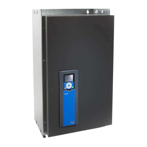
This manual is copyright of Vacon Plc. All Rights Reserved. ABOUT THE PRODUCT This manual describes the Vacon 100 Enclosed Drive. The power range of the drive is between 75-800 kW, and its voltage range is 380-500 V or 525-690 V. The drive comes installed in a cabinet, and is available in 4 different frame sizes: MR8, MR9, MR10 and MR12. - Page 4 VACON · 4 TEL. +358 (0)201 2121 · FAX +358 (0)201 212 205...
-
Page 5: Table Of Contents
Cable installation in MR8-MR12 5.4.1 Installing the cables 6 Control compartment The control compartment of the enclosed drive Fieldbus connection 6.2.1 Using fieldbus through an Ethernet cable 6.2.2 Using fieldbus through an RS485 cable 24-HOUR SUPPORT +358 (0)201 212 575 · EMAIL: VACON@VACON.COM... - Page 6 AC drive power ratings 9.1.1 Mains voltage 380-500 V 9.1.2 Mains voltage 525-690 V Vacon 100 FLOW - technical data ® 10 Technical data on control connections 10.1 Technical data on control connections TEL. +358 (0)201 2121 · FAX +358 (0)201 212 205...
-
Page 7: Approvals
APPROVALS VACON · 7 APPROVALS Here are the approvals that have been granted to this Vacon product. 1. EC Declaration of conformity Find the EC Declaration of Conformity on the next page. • 2. UL approval * cULus approval file number E171278. - Page 8 Product name: Vacon 100 AC drive Model Designation: Wall-Mounted Drives: Vacon 0100 3L 0003 2...0310 2 Vacon 0100 3L 0003 4...0310 4 Vacon 0100 3L 0003 5...0310 5 Vacon 0100 3L 0004 6...0208 6 Vacon 0100 3L 0007 7...0208 7 IP00 Drives: Vacon 0100 3L 0140 2...0310 2...
-
Page 9: Safety
Do not touch the components of the power unit when the drive is connected to mains. The components are live when the drive is connected to mains. A contact with this voltage is very dangerous. 24-HOUR SUPPORT +358 (0)201 212 575 · EMAIL: VACON@VACON.COM... -
Page 10: Caution
VACON · 10 SAFETY WARNING! Do not touch the motor cable terminals U, V, W, the brake resistor terminals or the DC terminals when the drive is connected to mains. These terminals are live when the drive is connected to mains, also when the motor does not operate. -
Page 11: Grounding And Earth Fault Protection
See chapter 5 Power cabling. OR c) There must be a terminal for a second protective grounding conductor in the same cross-sectional area as the first protective grounding conductor. 24-HOUR SUPPORT +358 (0)201 212 575 · EMAIL: VACON@VACON.COM... -
Page 12: Using An Rcd Or An Rcm Device
REMARQUE Vous pouvez télécharger les versions anglaise et française des manuels produit contenant l'en- semble des informations de sécurité, avertissements et mises en garde applicables sur le site www.vacon.com/ downloads. TEL. +358 (0)201 2121 · FAX +358 (0)201 212 205... -
Page 13: Receiving The Delivery
Cust. Ord. No: 20528906 Marks: Vacon Pasific Made by Vacon Fig. 2: The package label of Vacon AC drives A. The batch ID F. The nominal output current B. The order number of Vacon G. The IP class C. The type designation code H. -
Page 14: Type Designation Code
RECEIVING THE DELIVERY TYPE DESIGNATION CODE The type designation code of Vacon is made of standard codes and optional codes. Each part of the type designation code agrees to the data in your order. The code can have this format,... -
Page 15: Removing The Packaging And Lifting The Ac Drive
Do not remove the package material before you install the AC drive. Put the drive onto a level base. Move the drive in the vertical position. Use a hoist to move the drive. 24-HOUR SUPPORT +358 (0)201 212 575 · EMAIL: VACON@VACON.COM... - Page 16 VACON · 16 RECEIVING THE DELIVERY If you move more than 1 drive at a time, use rollers. LIFTING THE ENCLOSED DRIVE Remove the drive from the package. >60° Use a lifting device that is sufficiently strong for the weight of the drive.
-
Page 17: Product Modified" Label
To make sure that the waste is recycled correctly, send the waste to a recycling centre. You can also send the waste back to the manufacturer. Obey the local and other applicable regulations. 24-HOUR SUPPORT +358 (0)201 212 575 · EMAIL: VACON@VACON.COM... -
Page 18: Mounting
VACON · 18 MOUNTING MOUNTING DIMENSIONS OF THE CABINET, IEC Install the AC drive in a vertical position on level ground. Attach the drive with screws to the wall and/or the floor. Ø13 Ø13 Ø13 Fig. 3: The dimensions of the default cabinet, MR8, [mm]... - Page 19 MOUNTING VACON · 19 Ø13 Ø13 Ø13 Fig. 4: The dimensions of the default cabinet, MR9 and MR10, [mm] 24-HOUR SUPPORT +358 (0)201 212 575 · EMAIL: VACON@VACON.COM...
-
Page 20: Dimensions Of The Cabinet, Nam
VACON · 20 MOUNTING Ø 13 Ø 13 1135 Ø 13 1199 1206 Fig. 5: The dimensions of the default cabinet, MR12, [mm] DIMENSIONS OF THE CABINET, NAM Install the AC drive in a vertical position on level ground. Attach the drive with screws to the wall and/or the floor. - Page 21 MOUNTING VACON · 21 Ø13 Ø13 Ø13 639.5 Fig. 6: The dimensions of the default cabinet, MR8, [mm] 24-HOUR SUPPORT +358 (0)201 212 575 · EMAIL: VACON@VACON.COM...
- Page 22 VACON · 22 MOUNTING Ø13 Ø13 Ø13 638.5 Fig. 7: The dimensions of the default cabinet, MR9 and MR10, [mm] TEL. +358 (0)201 2121 · FAX +358 (0)201 212 205...
- Page 23 MOUNTING VACON · 23 Ø13 Ø13 1135 Ø13 1199 1206 Fig. 8: The dimensions of the default cabinet, MR12, [mm] 24-HOUR SUPPORT +358 (0)201 212 575 · EMAIL: VACON@VACON.COM...
-
Page 24: The Options
VACON · 24 MOUNTING THE OPTIONS Table 5: The options and their codes Group Name Code Auxiliary equipment Motor heater control +CAMH Cabinet heater +CACH Cabinet light +CACL Cabinet power supply for accesso- Auxiliary voltage transformer +CAPT ries 24 VDC power supply... - Page 25 +CACL: CABINET LIGHT With this option the control compartment will have a light as default by an internal auxiliary transformer or as an option by an external auxiliary voltage supply connected to –XD1.1. 24-HOUR SUPPORT +358 (0)201 212 575 · EMAIL: VACON@VACON.COM...
- Page 26 VACON · 26 MOUNTING The requirements: +CAPU Auxiliary AC supply terminals or +CAPT Auxiliary voltage transformer -FCC -EA1 -XD1 -XD1 Fig. 11: The cabinet light +CAPT: AUXILIARY VOLTAGE TRANSFORMER This option provides the supply of auxiliary voltage for other options. The supply for the auxiliary transformer is taken from mains.
- Page 27 This option provides the STO (Safe Torque Off) function with the OPT-BJ option board and an emergency stop push button on the door of the control compartment. The STO Channel 1 and 24-HOUR SUPPORT +358 (0)201 212 575 · EMAIL: VACON@VACON.COM...
- Page 28 VACON · 28 MOUNTING STO Channel 2 are wired to the emergency stop push button. The STO function corresponds to an emergency stop category 0. See the user manual of the OPT-BJ option board for the regulations and the certified safety functions.
-
Page 29: Installation Of The Cabinet
To use the fixing bracket, first attach it to the floor. Slide the edge of the cabinet plinth under the fixing bracket. Then attach the 2 fixing points at the front bottom. 24-HOUR SUPPORT +358 (0)201 212 575 · EMAIL: VACON@VACON.COM... -
Page 30: Cooling And Free Space Around The Ac Drive
VACON · 30 MOUNTING NOTE! If you have multiple cabinet sections (for example with MR12 or top cabling sections), these steps must be done for each section. Fig. 16: The fixing points of the cabinet A. The 4 fixing points at the bottom C. - Page 31 [kW] x 0.025 loss It is possible that there will be an increase of 0-0.5% in the power loss when you have options in the cabinet. Fig. 17: The circulation of cooling air 24-HOUR SUPPORT +358 (0)201 212 575 · EMAIL: VACON@VACON.COM...
-
Page 32: The Optional Back Channel Cooling
VACON · 32 MOUNTING Table 6: The necessary quantity of cooling air Frame The quantity of cooling air [m MR10 1400 MR12 2 x 1400 THE OPTIONAL BACK CHANNEL COOLING You can also use the back channel cooling option (+CHCB) for the cooling of the AC drive. - Page 33 If you use long air ducts in addition to the duct adapter flanges, use a duct fan or equivalent to prevent back pressure. Back pressure must be prevented because it decreases the performance of the drive. Fig. 18: Dimensions for the back channel cooling, MR8 24-HOUR SUPPORT +358 (0)201 212 575 · EMAIL: VACON@VACON.COM...
- Page 34 VACON · 34 MOUNTING Fig. 19: Dimensions for the back channel cooling, MR9 and MR12 TEL. +358 (0)201 2121 · FAX +358 (0)201 212 205...
-
Page 35: Power Cabling
The table also shows the typical symmetrically shielded copper and aluminum types of the cables that can be used with the AC drive. NOTE! The mains cable and fuse sizes are valid up to a cable length of 100 m, with mains = 20 kA. -FC1 -TA1 Fig. - Page 36 VACON · 36 POWER CABLING The dimensions of the cables agree with the requirements of the standards EN 60204-1 and IEC 60364-5-52: 2001. The cables are PVC-isolated. • The maximum ambient temperature is +30 °C. • The maximum temperature of the cable surface is +70 °C.
- Page 37 4x(3x185+57) (Al) MR12 4x(3x150+70) (Cu) 0920 5 2 x 500 4x(3x240+72) (Al) 4x(3x185+95) (Cu) 1040 5 1040 2 x 630 6x(3x150+41) (Al) 4x(3x240+120) (Cu) 1180 5 1180 2 x 630 6x(3x185+57) (Al) 24-HOUR SUPPORT +358 (0)201 212 575 · EMAIL: VACON@VACON.COM...
- Page 38 VACON · 38 POWER CABLING Table 8: The recommended cables and fuses in 525-690 V (IEC) Frame Type IL [A] Mains fuse Mains and motor Mains and Grounding (gG/gL) [A] cable (Cu/AI) [mm2] motor cable terminal, terminals, bolt size bolt size...
- Page 39 13000 0650 5 NH2UD69V630PV 5000 0730 5 NH2UD69V700PV 5700 0820 5 NH3UD69V900PV 7000 MR12 0920 5 NH3UD69V1000PV 1000 8600 1040 5 1040 NH3UD69V1000PV 1000 8600 1180 5 1180 PC73UD90V10CPA 1000 13000 24-HOUR SUPPORT +358 (0)201 212 575 · EMAIL: VACON@VACON.COM...
- Page 40 VACON · 40 POWER CABLING Table 10: Drive fuses, 525-690 V, Mersen (IEC) Frame Type Catalogue number of the Fuse Number Fuse Minimum fuse rating of fuses size prospective needed short circuit current [A] 0080 7 NH1UD69V125PV 0100 7 NH1UD69V160PV...
- Page 41 10500 0650 5 170M5814D 5750 0730 5 170M5814D 5750 0820 5 170M6813D 6000 MR12 0920 5 170M6814D 1000 7500 1040 5 1040 170M6892D 1100 8500 1180 5 1180 170M8554D 1250 10500 24-HOUR SUPPORT +358 (0)201 212 575 · EMAIL: VACON@VACON.COM...
-
Page 42: Cable And Fuse Sizes, Nam
VACON · 42 POWER CABLING Table 12: Drive fuses, 525-690 V, Bussmann (IEC) Frame Type Catalogue number of the Fuse Number Fuse Minimum fuse rating of fuses size prospective needed short circuit current [A] 0080 7 170M3814D 0100 7 170M3815D... - Page 43 POWER CABLING VACON · 43 NOTE! The mains cable and fuse sizes are valid up to a cable length of 100 m, with mains = 20 kA. -FC1 -TA1 Fig. 22: The location of the fuses, MR8-MR10 A. The mains fuses B.
- Page 44 VACON · 44 POWER CABLING Table 13: The recommended cables and terminal lugs in 380-500 V (NAM) Frame Type Mains and motor Mains and motor Grounding cable (Cu) [AWG/ cable terminal, bolt and kcmil] termination, lug size Panduit terminal part number...
- Page 45 0460 7 4x(3x1/0+3x10) LCAX1/0-12-X P10-56R-L 0520 7 4x(3x2/0+3x10) LCAX2/0-12-X P10-56R-L 0590 7 4x(3x4/0+3x8) LCAX4/0-12-X LCAX8-56-L MR12 0650 7 4x(3x4/0+3x8) LCAX4/0-12-X LCAX8-56-L 0730 7 4x(3x4/0+3x8) LCAX4/0-12-X LCAX8-56-L 0820 7 4x(3x262+3x6) LCAX250-12-X LCAX6-56-L 24-HOUR SUPPORT +358 (0)201 212 575 · EMAIL: VACON@VACON.COM...
- Page 46 VACON · 46 POWER CABLING Table 15: Drive fuses, 380-500 V, Mersen (NAM) Frame Type Catalogue number of the Fuse Number Fuse Minimum fuse rating of fuses size prospective needed short circuit current [A] 0140 5 PC30UD69V250TF PSC30 1550 0170 5...
- Page 47 0460 7 PC32UD69V450TF PSC32 3000 0520 7 PC32UD69V450TF PSC32 3000 0590 7 PC32UD69V500TF PSC32 3400 MR12 0650 7 PC32UD69V550TF PSC32 3900 0750 7 PC32UD69V630TF PSC32 4700 0820 7 PC32UD69V700TF PSC32 5700 24-HOUR SUPPORT +358 (0)201 212 575 · EMAIL: VACON@VACON.COM...
-
Page 48: Brake Resistor Cables
NOTE! The different Vacon 100 applications have different functions. For example, the ® Vacon 100 FLOW does not have the dynamic braking or the brake resistor ® functions. TEL. +358 (0)201 2121 · FAX +358 (0)201 212 205... - Page 49 NOTE! The different Vacon 100 applications have different functions. For example, the ® Vacon 100 FLOW does not have the dynamic braking or the brake resistor ® functions. 24-HOUR SUPPORT +358 (0)201 212 575 · EMAIL: VACON@VACON.COM...
-
Page 50: Preparing For The Cable Installation
VACON · 50 POWER CABLING PREPARING FOR THE CABLE INSTALLATION Before you start, make sure that none of the components of the AC drive is live. Read • carefully the warnings in chapter 2 Safety. Make sure that the motor cables are sufficiently far from other cables. -
Page 51: Cable Installation In Mr8-Mr12
H. The PE bar N. The internal fan for IP54 Input air grill O. The main fan J. The terminals for the option +CAPU P. The cable entry plate for control cables 24-HOUR SUPPORT +358 (0)201 212 575 · EMAIL: VACON@VACON.COM... - Page 52 VACON · 52 POWER CABLING Fig. 25: The inside layout of MR9, without protective covers A. The output air grill K. The motor cable terminals with the B. The control connector of the power unit common mode and/or the du/dt filter C.
- Page 53 J. The motor cable terminals E. The mains cable terminals K. The service lid, and the main fan under it F. The 360-degree grounding L. The cable entry plate for control cables 24-HOUR SUPPORT +358 (0)201 212 575 · EMAIL: VACON@VACON.COM...
- Page 54 VACON · 54 POWER CABLING Fig. 27: The inside layout of MR12, without protective covers A. Power unit 1 E. The fuse switch linkage for the fuse B. Power unit 2 switch option. C. Optical fibre cables F. The DC link connection D.
-
Page 55: Installing The Cables
Make sure that the external grounding conductor is connected to the grounding bar. See chapter 2.4 Grounding and earth fault protection. 24-HOUR SUPPORT +358 (0)201 212 575 · EMAIL: VACON@VACON.COM... - Page 56 VACON · 56 POWER CABLING If you use many cables on one connector, put the cable lugs on top of each other. The picture shows the connection in MR8 and • MR9. A. The first cable lug B. The second cable lug C.
- Page 57 D. The second cable lug A. The bolt holder of the connector B. The first cable lug C. The connector D. The second cable lug E. The connection bush F. The third cable lug 24-HOUR SUPPORT +358 (0)201 212 575 · EMAIL: VACON@VACON.COM...
- Page 58 VACON · 58 POWER CABLING Expose the shield of all 3 cables to make a 360- degree connection with the grounding clamps for cable shield. IP21 IP54 Attach the terminal cover, and then the extension box cover. Close the cabinet door.
- Page 59 0144 7-0208 7 0385 5-0590 5 MR10 55-70 490-620 0261 7-0416 7 0650 5-1180 5 MR12 55-70 490-620 0460 7-0820 7 * = Counter torque is required for the mains cable terminals. 24-HOUR SUPPORT +358 (0)201 212 575 · EMAIL: VACON@VACON.COM...
-
Page 60: Control Compartment
VACON · 60 CONTROL COMPARTMENT CONTROL COMPARTMENT THE CONTROL COMPARTMENT OF THE ENCLOSED DRIVE The enclosed drive has a door-mounted control compartment, separated from the cabinet section, for the mains and motor cable terminals. You can have an access to the control compartment through a separate door located on the cabinet door. - Page 61 The terminals for control cabling cable ties (default) D. The cable carrier J. Grounding clamps for cable shield E. The cable ducts F. The extended I/O terminals (+CTID) to be used freely 24-HOUR SUPPORT +358 (0)201 212 575 · EMAIL: VACON@VACON.COM...
- Page 62 VACON · 62 CONTROL COMPARTMENT Fig. 29: The control compartment components of the cabinet A. The insulation fault sensor (+CPIF) K. The emergency stop reset button B. The 24 VDC power supply (+CAPD) (+CPS1) C. The emergency stop Cat 1 (+CPS1) L.
-
Page 63: Fieldbus Connection
Put the cover of the drive back. Keep the distance between the Ethernet cable and the motor cable at a minimum of 30 cm. See more in the Installation Manual of the fieldbus that you have. 24-HOUR SUPPORT +358 (0)201 212 575 · EMAIL: VACON@VACON.COM... -
Page 64: Using Fieldbus Through An Rs485 Cable
VACON · 64 CONTROL COMPARTMENT 6.2.2 USING FIELDBUS THROUGH AN RS485 CABLE Table 22: RS485 cable data Item Description The plug type 2.5 mm The cable type STP (shielded twisted pair), Belden 9841 or almost the same The cable length So that it agrees with the fieldbus. - Page 65 A = negative • B = positive • Attach the shield of the cable to the frame of the drive with a grounding clamp for control cable to make a grounding connection. 24-HOUR SUPPORT +358 (0)201 212 575 · EMAIL: VACON@VACON.COM...
- Page 66 VACON · 66 CONTROL COMPARTMENT If the drive is the last device on the fieldbus line, set the bus termination. a) Find the DIP switches on the left side of the control unit of the drive. b) Set the DIP switch of the RS485 bus termination to the ON position.
- Page 67 CONTROL COMPARTMENT VACON · 67 NOTE! If you do power-down to the last device, there is no bus termination. 24-HOUR SUPPORT +358 (0)201 212 575 · EMAIL: VACON@VACON.COM...
-
Page 68: Commissioning And Additional Instructions
VACON · 68 COMMISSIONING AND ADDITIONAL INSTRUCTIONS COMMISSIONING AND ADDITIONAL INSTRUCTIONS COMMISSIONING SAFETY Before you start the commissioning, read these warnings. WARNING! Do not touch the internal components or the circuit boards of the drive when the drive is connected to mains. These components are live. A contact with this voltage is very dangerous. -
Page 69: Operation Of The Motor
If your mains is impedance-grounded (IT), the AC drive must have the EMC protection level C4. If your drive has the EMC protection level C3, it is necessary to change it to C4. To do this, remove the EMC jumper. 24-HOUR SUPPORT +358 (0)201 212 575 · EMAIL: VACON@VACON.COM... -
Page 70: The Emc Jumper In Mr8
VACON · 70 COMMISSIONING AND ADDITIONAL INSTRUCTIONS WARNING! Do not make changes in the AC drive when it is connected to mains. The components of the drive are live when the drive is connected to mains. CAUTION! Before you connect the AC drive to mains, make sure that the EMC level of the drive is correct. -
Page 71: The Emc Jumper In Mr9
7.5.2 THE EMC JUMPER IN MR9 Change the EMC protection of the AC drive from level C3 to level C4. THE EMC JUMPER 1 Open the covers of the AC drive. 24-HOUR SUPPORT +358 (0)201 212 575 · EMAIL: VACON@VACON.COM... - Page 72 VACON · 72 COMMISSIONING AND ADDITIONAL INSTRUCTIONS Loosen the screws of the cover plate and remove it. Remove the EMC jumper. If you change the EMC level, write "The EMC level was changed" and the date on the "product Product modified Date: changed"...
-
Page 73: The Emc Jumper In Mr10 And Mr12
FINDING THE EMC JUMPER, WITH AN EXTENSION BOX Remove the covers of the AC drive. In MR12, do these steps for each power unit. • Also remove the fuse switch linkage. 24-HOUR SUPPORT +358 (0)201 212 575 · EMAIL: VACON@VACON.COM... -
Page 74: Maintenance
VACON · 74 COMMISSIONING AND ADDITIONAL INSTRUCTIONS Find the EMC jumper between the terminals L2 and Remove the EMC jumper. If you change the EMC level, write "The EMC level was changed" and the date on the "product Product modified Date: modified"... -
Page 75: Replacing The Air Filters Of The Ac Drive
Replace the fan power supply. 10 years Replace the battery of the RTC. The battery is optional. This table is valid for Vacon components. To do maintenance on components that are made by other manufacturers, obey the manual of the component in question. 7.6.2 REPLACING THE AIR FILTERS OF THE AC DRIVE Clean or replace the filters of the cabinet regularly. -
Page 76: Replacing The Fans Of The Ac Drive
VACON · 76 COMMISSIONING AND ADDITIONAL INSTRUCTIONS REPLACING THE FILTER ON THE CABINET DOOR To remove the cover of the filter, pull it out and up. Clean or replace the filter. Put the cover of the filter back. 7.6.3 REPLACING THE FANS OF THE AC DRIVE 7.6.3.1... - Page 77 Remove the cover of the AC drive. Remove the fan power supply. See the previous instructions. Remove the 4 screws that hold the main fan unit. Lift off the main fan unit. 24-HOUR SUPPORT +358 (0)201 212 575 · EMAIL: VACON@VACON.COM...
- Page 78 VACON · 78 COMMISSIONING AND ADDITIONAL INSTRUCTIONS To release the fan from the cover plate, remove the 4 screws. A. The fan cable Release the grommet on the fan cable from the cover plate and pull out the cable. Replace the main fan. Attach the screws.
- Page 79 2 > 3). Re-assemble the drive and connect the cables. 7.6.3.3 Replacing the fans in MR10 and MR12 Here are the instructions on how to replace the fans of the drive. 24-HOUR SUPPORT +358 (0)201 212 575 · EMAIL: VACON@VACON.COM...
- Page 80 VACON · 80 COMMISSIONING AND ADDITIONAL INSTRUCTIONS REPLACING THE MAIN FAN ASSEMBLY, MR10 AND MR12 Loosen the 8 screws and lift off the service lid. Disconnect the cables from each fan power supply. X61 X8 X61 X8 a) Disconnect the fan driver cable from connector X61.
-
Page 81: Replacing The Power Unit Of The Ac Drive
REPLACING THE POWER UNIT OF THE AC DRIVE 7.6.4.1 Replacing the power unit, MR8 Remove the protective covers of the drive. Disconnect all the power cables from the bottom of the power unit. 24-HOUR SUPPORT +358 (0)201 212 575 · EMAIL: VACON@VACON.COM... - Page 82 VACON · 82 COMMISSIONING AND ADDITIONAL INSTRUCTIONS Remove the 2 screws from the top of the power unit. TEL. +358 (0)201 2121 · FAX +358 (0)201 212 205...
- Page 83 COMMISSIONING AND ADDITIONAL INSTRUCTIONS VACON · 83 Remove the 6 screws from the bottom of the power unit. Pull the power unit out carefully until it is possible to use the front lifting holes. 24-HOUR SUPPORT +358 (0)201 212 575 · EMAIL: VACON@VACON.COM...
- Page 84 VACON · 84 COMMISSIONING AND ADDITIONAL INSTRUCTIONS Attach the lifting hooks to the front lifting holes and lift the power unit out of the cabinet. 7.6.4.2 Replacing the power unit, MR9 Remove the protective covers of the drive. Disconnect all the power cables from the bottom of the power unit.
- Page 85 COMMISSIONING AND ADDITIONAL INSTRUCTIONS VACON · 85 Remove the 2 screws from the top of the power unit. Also remove the lifting lugs. You will re-attach them later. 24-HOUR SUPPORT +358 (0)201 212 575 · EMAIL: VACON@VACON.COM...
- Page 86 VACON · 86 COMMISSIONING AND ADDITIONAL INSTRUCTIONS Remove the 8 screws from the bottom of the power unit. Pull the power unit out carefully until it is possible to re-attach the lifting lugs. TEL. +358 (0)201 2121 · FAX +358 (0)201 212 205...
- Page 87 VACON · 87 Re-attach the lifting lugs. You can use the extra nut that is on the screw. Remove the nut and attach it to the other side of the lifting lug. 24-HOUR SUPPORT +358 (0)201 212 575 · EMAIL: VACON@VACON.COM...
- Page 88 VACON · 88 COMMISSIONING AND ADDITIONAL INSTRUCTIONS Attach the lifting hooks to the lifting lugs and lift the power unit out of the cabinet. 7.6.4.3 Replacing the power unit, MR10 and MR12 Remove the protective covers of the drive. In MR12, do these steps for each cabinet.
- Page 89 Remove the 4 screws of the lower cover of the power unit and remove the cover. Disconnect all the power cables from the bottom of the power unit. Remove the 2 screws from the top of the power unit. 24-HOUR SUPPORT +358 (0)201 212 575 · EMAIL: VACON@VACON.COM...
-
Page 90: Downloading The Software
VACON · 90 COMMISSIONING AND ADDITIONAL INSTRUCTIONS Remove the 2 screws from the bottom of the power unit. Pull the power unit out carefully until the front lifting holes are available. Attach the lifting hooks to the front lifting holes and lift the power unit out of the cabinet. - Page 91 Before you do electrical work, make sure that there is no voltage. DOWNLOADING WITH MAINS, MR8-MR12 When the drive is supplied from mains, you can download a new software with the Vacon Loader PC tool and a CAB-USB/RS485 cable. To download a new software, connect the PC into the control panel connector with the CAB-USB/ RS485 cable.
- Page 92 Remove the control panel. Connect the PC to the control panel connector in the control unit with an CAB-USB/RS485 cable. Start the Vacon Loader PC tool. Start the downloading of the software. After the downloading is complete, disconnect the PC and attach the control panel into the control unit.
- Page 93 Before you connect the drive to mains, make sure that the front cover and the cable cover of the drive are closed. The connections of the AC drive are live when the drive is connected to mains. 24-HOUR SUPPORT +358 (0)201 212 575 · EMAIL: VACON@VACON.COM...
-
Page 94: Ac Drive Power Ratings
TECHNICAL DATA, VACON® 100 TECHNICAL DATA, VACON ® AC DRIVE POWER RATINGS 8.1.1 MAINS VOLTAGE 380-500 V Table 24: The power ratings of Vacon 100 in mains voltage 380-500V, 50-60 Hz, 3~ ® Frame Drive Loadability Motor shaft power type... -
Page 95: Mains Voltage 525-690 V
TECHNICAL DATA, VACON® 100 VACON · 95 8.1.2 MAINS VOLTAGE 525-690 V Table 25: The power ratings of Vacon 100 in mains voltage 525-690 V, 50-60 Hz, 3~ ® Frame Drive Loadability Motor shaft power type High 600 V mains... - Page 96 VACON · 96 TECHNICAL DATA, VACON® 100 Table 26: The recommended brake resistor types and the calculated resistance of the drive, 380-500 V Frame Duty cycle Type of brake resistor Resistance [Ω] Light duty BRR 0105 LD 5 Heavy duty...
- Page 97 Table 28: The minimum resistance and the brake power, mains voltage 380-500 V Frame The minimum brake Brake power* @845 VDC resistance [Ω] [kW] 109.9 216.4 MR10 MR12 2 x 1.4 ** 24-HOUR SUPPORT +358 (0)201 212 575 · EMAIL: VACON@VACON.COM...
- Page 98 VACON · 98 TECHNICAL DATA, VACON® 100 Table 29: The minimum resistance and the brake power, mains voltage 525-690 V Frame The minimum brake Brake power* @1166 VDC resistance [Ω] [kW] MR10 MR12 2 x 2.5 ** * = When you use recommended resistor types.
-
Page 99: Vacon ® 100 - Technical Data
: Ambient temperature max. +40 °C overload 1.5 x I (1 min/10 min) Motor connection in 690 V drives: Ambient temperature max. +40 °C overload 1.5 x I (1 min/10 min) Output frequency 0-320 Hz (standard) Frequency resolution 0.01 Hz 24-HOUR SUPPORT +358 (0)201 212 575 · EMAIL: VACON@VACON.COM... -
Page 100: Technical Data, Vacon® 100
VACON · 100 TECHNICAL DATA, VACON® 100 Table 30: The technical data of the Vacon 100 AC drive ® Technical item or function Technical data Switching frequency (see 380-500 V parameter P3.1.2.3) MR8-MR12: • 1.5-6 kHz • Default: MR8: 3 kHz, MR9: 2 kHz, MR10: 2 •... - Page 101 Mechanical particles: IEC 60721-3-3, unit in oper- • ation, class 3S2 Ambient conditions Altitude 100% load capacity (no derating) up to 1000 m 1% derating for each 100m above 1000 m Maximum altitudes: 380-500 V: 4000 m (TN and IT systems) •...
- Page 102 VACON · 102 TECHNICAL DATA, VACON® 100 Table 30: The technical data of the Vacon 100 AC drive ® Technical item or function Technical data Vibration: 5-150 Hz Displacement amplitude 0.5 mm (peak) at 5-22 Hz EN61800-5-1 Maximum acceleration amplitude 1 G at 22-150 Hz...
- Page 103 Motor overload protection Yes. The motor overload protection activates at 110% of the full load current. Motor stall protection Motor underload protec- tion Short-circuit protection of +24 V and +10 V reference voltages 24-HOUR SUPPORT +358 (0)201 212 575 · EMAIL: VACON@VACON.COM...
-
Page 104: Technical Data, Vacon® 100 Flow
TECHNICAL DATA, VACON 100 FLOW ® AC DRIVE POWER RATINGS 9.1.1 MAINS VOLTAGE 380-500 V Table 31: The power ratings of Vacon 100 FLOW in mains voltage 380-500 V, 50-60 Hz, 3~ ® Frame Drive type Loadability Motor shaft power Continuous... -
Page 105: Mains Voltage 525-690 V
TECHNICAL DATA, VACON® 100 FLOW VACON · 105 9.1.2 MAINS VOLTAGE 525-690 V Table 32: The power ratings of Vacon 100 FLOW in mains voltage 525-690 V, 50-60 Hz, 3~ ® Frame Drive type Loadability Motor shaft power Continuous Input... -
Page 106: Vacon ® 100 Flow - Technical Data
VACON · 106 TECHNICAL DATA, VACON® 100 FLOW VACON 100 FLOW - TECHNICAL DATA ® Table 33: The technical data of the Vacon 100 FLOW AC drive ® Technical item or function Technical data Input voltage U 380-500 V, 525-690 V, -10%...+10% Input frequency 50-60 Hz, -5...+10%... - Page 107 Automatic switching frequency derating in case of overload. Frequency reference: Resolution 0.1% (10-bit), accuracy ±1% Resolution 0.01 Hz Analogue input Panel reference Field weakening point 8-320 Hz Acceleration time 0.1-3000 s Deceleration time 0.1-3000 s 24-HOUR SUPPORT +358 (0)201 212 575 · EMAIL: VACON@VACON.COM...
- Page 108 Mechanical particles: IEC 60721-3-3, unit in oper- • ation, class 3S2 Ambient conditions Altitude 100% load capacity (no derating) up to 1000 m 1-% derating for each 100m above 1000 m Maximum altitudes: 380-500 V: 4000 m (TN and IT systems) •...
- Page 109 Noise level MR8: 58-73 MR9: 54-75 MR10/MR12: 58-75 EN 61800-5-1, CE (See the nameplate of the drive for Safety more approvals.) 24-HOUR SUPPORT +358 (0)201 212 575 · EMAIL: VACON@VACON.COM...
- Page 110 VACON · 110 TECHNICAL DATA, VACON® 100 FLOW Table 33: The technical data of the Vacon 100 FLOW AC drive ® Technical item or function Technical data Overvoltage trip limit Mains voltage 500 V: 911 VDC Mains voltage 690 V: 1258 VDC Undervoltage trip limit Depends on mains voltage (0.8775 x mains voltage):...
-
Page 111: Technical Data On Control Connections
Analogue input common (cur- Differential input if not connected to ground rent) Allows ±20 V common mode voltage to GND +24 V, ±10%, max volt. ripple < 100 mVrms 24 V aux. voltage max. 250 mA Short-circuit protected Ground for reference and controls (connected internally to I/O ground frame ground through 1 MΩ) - Page 112 VACON · 112 TECHNICAL DATA ON CONTROL CONNECTIONS Table 34: The standard I/O board Standard I/O board Terminal Signal Technical information Digital inputs can be disconnected from ground, see chapter Common A for DIN1-DIN6 Isolation of digital inputs from ground in the Installation Man- ual.
- Page 113 This is to prevent welding on the relay contacts. Refer to standard EN 60204-1, section 7.2.9. 24-HOUR SUPPORT +358 (0)201 212 575 · EMAIL: VACON@VACON.COM...
- Page 114 VACON · 114 TECHNICAL DATA ON CONTROL CONNECTIONS Table 36: The optional relay board (+SBF4) Terminal Signal Technical information Change-over contact (SPDT) relay. 5.5 mm isolation between channels. Switching capacity 24 VDC/8 A Relay output 1 * • 250 VAC/8 A •...
- Page 116 Document ID: Vacon Ltd Member of the Danfoss Group Rev. B Runsorintie 7 65380 Vaasa Sales code: DOC-INS100ED+DLUK Finland...
Need help?
Do you have a question about the 100 and is the answer not in the manual?
Questions and answers