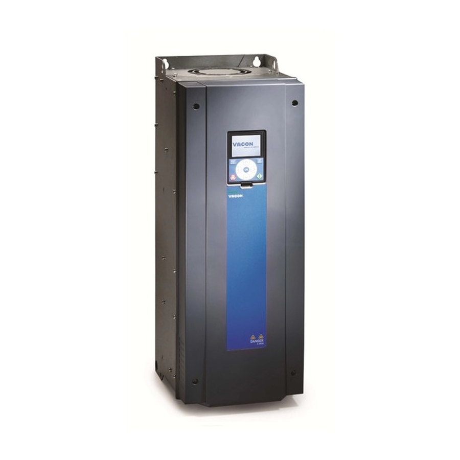
Sign In
Upload
Manuals
Brands
Vacon Manuals
Controller
100 HVAC
Vacon 100 HVAC Manuals
Manuals and User Guides for Vacon 100 HVAC. We have
7
Vacon 100 HVAC manuals available for free PDF download: Applications Manual, Installation Manual, User Manual, Technical Manual
Vacon 100 HVAC Applications Manual (201 pages)
Brand:
Vacon
| Category:
Controller
| Size: 1.6 MB
Table of Contents
About this Manual
3
Functions of the Vacon ® AC Drive
5
Table of Contents
7
1 Quick Startup Guide
11
Control Panel and Keypad
11
The Displays
11
First Start-Up
12
Description of the Applications
13
Vacon HVAC Application
13
2 Wizards
20
PID Mini-Wizard
20
Multi-Pump Mini-Wizard
21
Fire Mode Wizard
22
3 User Interfaces
24
Navigation on the Keypad
24
Using the Graphical Display
26
Editing the Values
26
Resetting a Fault
29
The Funct Button
29
Copying the Parameters
33
Comparing the Parameters
35
Help Texts
36
Using the Favourites Menu
37
Using the Text Display
37
Editing the Values
38
Resetting a Fault
39
The Funct Button
39
Menu Structure
42
Quick Setup
43
Monitor
43
Vacon Live
44
4 Monitoring Menu
46
Monitor Group
46
Multimonitor
46
Basic
47
Timer Functions Monitoring
49
PID1 Controller Monitoring
50
PID2 Controller Monitoring
51
Multi-Pump Monitoring
51
Fieldbus Process Data Monitoring
52
5 Parameters Menu
53
Group 3.1: Motor Settings
53
Group 3.2: Start/Stop Setup
56
Group 3.3: Control Reference Settings
58
Group 3.4: Ramp and Brakes Setup
60
Group 3.5: I/O Configuration
61
Group 3.6: Fieldbus Data Mapping
69
Group 3.7: Prohibit Frequencies
70
Group 3.8: Limit Supervisions
71
Group 3.9: Protections
72
Group 3.10: Automatic Reset
74
Group 3.11: Timer Functions
75
Group 3.12: PID-Controller
78
Group 3.13: PID-Controller
83
Group 3.14: Multipump
86
Group 3.16: Fire Mode
87
Group 3.17: Application Settings
88
Group 3.18: Kwh Pulse Output Settings
88
6 Diagnostics Menu
89
Active Faults
89
Reset Faults
89
Fault History
89
Total Counters
90
Trip Counters
91
Software Info
92
7 O and Hardware Menu
93
Basic I/O
93
Option Board Slots
95
Real Time Clock
96
Power Unit Settings
96
Keypad
98
Fieldbus
98
8 User Settings, Favourites and User Level Menus
99
User Settings
99
Parameter Backup
100
Favourites
101
Adding an Item to the Favourites
101
Removing an Item from the Favourites
102
User Levels
103
Changing the Access Code of the User Levels
103
9 Monitoring Value Descriptions
105
Basic
105
Timer Functions
107
PID1 Controller
108
PID2 Controller
109
Multi-Pump
109
Fieldbus Data
110
Tel. +358 (0)201 2121 · Fax +358 (0)201 212
110
10 Parameter Descriptions
112
Motor Settings
112
Motor Nameplate Parameters
112
Motor Control Parameters
113
Start/Stop Setup
117
References
124
Frequency Reference
124
Preset Frequencies
125
Motor Potentiometer Parameters
127
Ramps and Brakes Setup
128
I/O Configuration
131
Programming of Digital and Analogue Inputs
131
B. the Name of the Parameter
133
Digital Inputs
137
Analogue Inputs
142
Digital Outputs
143
Analogue Outputs
145
Fieldbus Data Map
148
Prohibit Frequencies
149
Limit Supervisions
151
Protections
152
Motor Thermal Protections
153
Motor Stall Protection
155
Underload (Dry Pump) Protection
157
Automatic Reset
160
Timer Functions
162
Pid Controller 1
166
Basic Settings
166
Setpoints
168
Feedback
169
Feedforward
170
Process Supervision
171
Pressure Loss Compensation
173
Pid Controller 2
174
Basic Settings
174
Multi-Pump Function
175
Fire Mode
183
Application Settings
186
Kwh Pulse Output
186
11 Fault Tracing
187
A Fault Comes into View
187
Resetting with the Reset Button
187
Resetting with a Parameter in the Graphical Display
187
Resetting with a Parameter in the Text Display
188
Fault History
189
Examining the Fault History in the Graphical Display
189
Examining the Fault History in the Text Display
190
Fault Codes
192
Advertisement
vacon 100 HVAC Applications Manual (180 pages)
Brand:
vacon
| Category:
Controller
| Size: 1.74 MB
Table of Contents
About this Manual
3
Functions of the Vacon ® AC Drive
5
Table of Contents
7
1 Quick Startup Guide
10
Control Panel and Keypad
10
The Displays
10
First Start-Up
11
Description of the Applications
12
Vacon HVAC Application
12
2 Wizards
19
PID Mini-Wizard
19
Multi-Pump Mini-Wizard
20
Fire Mode Wizard
21
3 User Interfaces
23
Navigation on the Keypad
23
Using the Graphical Display
25
Editing the Values
25
Resetting a Fault
28
The Funct Button
28
Copying the Parameters
32
Comparing the Parameters
34
Help Texts
35
Using the Favourites Menu
36
Using the Text Display
36
Editing the Values
37
Resetting a Fault
38
The Funct Button
38
Menu Structure
41
Quick Setup
42
Monitor
42
Vacon Live
43
4 Monitoring Menu
45
Monitor Group
45
Multimonitor
45
Basic
46
Timer Functions Monitoring
49
PID1 Controller Monitoring
50
PID2 Controller Monitoring
51
Multi-Pump Monitoring
51
Fieldbus Process Data Monitoring
52
5 Parameters Menu
54
Group 3.1: Motor Settings
54
Group 3.2: Start/Stop Setup
59
Group 3.3: Control Reference Settings
61
Group 3.4: Ramp and Brakes Setup
65
Group 3.5: I/O Configuration
67
Group 3.6: Fieldbus Data Mapping
77
Group 3.7: Prohibit Frequencies
78
Group 3.8: Limit Supervisions
79
Group 3.9: Protections
80
Group 3.10: Automatic Reset
84
Group 3.11: Timer Functions
86
Group 3.12: PID-Controller
90
Group 3.13: PID-Controller
98
Group 3.14: Multipump
102
Group 3.16: Fire Mode
104
Group 3.17: Application Settings
106
Group 3.18: Kwh Pulse Output Settings
106
6 Diagnostics Menu
107
Active Faults
107
Reset Faults
107
Fault History
107
Total Counters
108
Trip Counters
109
Software Info
110
7 O and Hardware Menu
111
Basic I/O
111
Option Board Slots
113
Real Time Clock
114
Power Unit Settings
114
Keypad
116
Fieldbus
116
8 User Settings, Favourites and User Level Menus
117
User Settings
117
Parameter Backup
118
Favourites
119
Adding an Item to the Favourites
119
Removing an Item from the Favourites
120
User Levels
121
Changing the Access Code of the User Levels
121
9 Parameter Descriptions
123
Motor Settings
123
Start/Stop Setup
125
References
132
Ramps and Brakes Setup
133
I/O Configuration
134
Programming of Digital and Analogue Inputs
134
B. the Name of the Parameter
136
Digital Inputs
140
Analogue Inputs
141
Digital Outputs
143
Prohibit Frequencies
144
Protections
145
Motor Thermal Protections
145
Motor Stall Protection
147
Underload (Dry Pump) Protection
148
Automatic Reset
150
Timer Functions
151
PID Controller
154
Setpoints
154
Feedforward
155
Process Supervision
156
Pressure Loss Compensation
157
PID Controller
158
Multipump Function
159
Fire Mode
165
Application Settings
166
10 Fault Tracing
167
A Fault Comes into View
167
Resetting with the Reset Button
167
Resetting with a Parameter in the Graphical Display
167
Resetting with a Parameter in the Text Display
168
Fault History
169
Examining the Fault History in the Graphical Display
169
Examining the Fault History in the Text Display
170
Fault Codes
172
Vacon 100 HVAC Installation Manual (156 pages)
wall-mounted drives
Brand:
Vacon
| Category:
Controller
| Size: 6.96 MB
Table of Contents
About this Manual
3
Table of Contents
5
Approvals
8
Safety
10
The Safety Symbols Used in the Manual
10
Warning
10
Caution
11
Grounding and Earth Fault Protection
12
Electro-Magnetic Compatibility (EMC)
13
Using an RCD or an RCM Device
13
Receiving the Delivery
15
Package Label
15
Type Designation Code
16
Contents of the Delivery
16
Removing the Packaging and Lifting the AC Drive
16
Weight of the AC Drive
16
Lifting the Frames MR8 and MR9
17
Accessories
18
Frame MR4
19
Frame MR5
19
Frame MR6
20
Frame MR7
21
Frame MR8
21
Frame MR9
22
Product Modified" Label
22
Disposal
22
Mounting
23
General Information about Mounting
23
Dimensions for Wall Mounting
23
Wall Mounting of MR4
23
Wall Mounting of MR5
24
Wall Mounting of MR6
25
Wall Mounting of MR7
26
Wall Mounting of MR8, IP21 and IP54
27
Wall Mounting of MR8, IP00
28
Wall Mounting of MR9, IP21 and IP54
29
Wall Mounting of MR9, IP00
30
Dimensions for Wall Mounting, North America
31
Wall Mounting of MR4, North America
31
Wall Mounting of MR5, North America
32
Wall Mounting of MR6, North America
33
Wall Mounting of MR7, North America
34
Wall Mounting of MR8, North America
35
Wall Mounting of MR8, UL Open Type, North America
36
Wall Mounting of MR9, North America
37
Wall Mounting of MR9, UL Open Type, North America
38
Dimensions for Flange Mounting
38
Flange Mounting of MR4
42
Flange Mounting of MR5
43
Flange Mounting of MR6
44
Flange Mounting of MR7
45
Flange Mounting of MR8
46
Flange Mounting of MR9
47
Dimensions for Flange Mounting, North America
48
Flange Mounting of MR4, North America
48
Flange Mounting of MR5, North America
49
Flange Mounting of MR6, North America
50
Flange Mounting of MR7, North America
51
Flange Mounting of MR8, North America
52
Flange Mounting of MR9, North America
53
Cooling
54
Power Cabling
57
Cable Connections
57
UL Standards on Cabling
58
Cable Dimensioning and Selection
58
Cable and Fuse Sizes
58
Cable and Fuse Sizes, North America
63
Brake Resistor Cables
68
Preparing for the Cable Installation
69
Cable Installation
69
Frames MR4 to MR7
69
Frames MR8 to MR9
76
Installation in a Corner-Grounded Network
88
Control Unit
89
Control Unit Components
89
Control Unit Cabling
90
Selection of the Control Cables
90
Control Terminals and DIP Switches
91
Fieldbus Connection
95
Using Fieldbus through an Ethernet Cable
96
Using Fieldbus through an RS485 Cable
99
Installation of Option Boards
103
The Installation Procedure
104
Installation of a Battery for the Real Time Clock (RTC)
105
Galvanic Isolation Barriers
105
Commissioning and Additional Instructions
107
Commissioning Safety
107
Commissioning of the Drive
107
Operation of the Motor
108
Checks before Starting the Motor
108
Measuring the Cable and Motor Insulation
108
Installation in a Marine Environment
109
Installation in an IT System
109
The EMC Jumper in MR4, MR5 and MR6
109
The EMC Jumper in MR7
112
The EMC Jumper in MR8
114
The EMC Jumper in MR9
115
Maintenance
116
Technical Data, Vacon
118
AC Drive Power Ratings
118
Mains Voltage 208-240 V
118
Mains Voltage 380-500 V
120
Mains Voltage 525-600 V
121
Mains Voltage 525-690 V
122
Overload Capability
122
Brake Resistor Ratings
123
Vacon ® 100 - Technical Data
128
Technical Data, Vacon® 100 Flow
133
AC Drive Power Ratings
133
Mains Voltage 208-240 V
133
Mains Voltage 380-500 V
135
Mains Voltage 525-600 V
136
Mains Voltage 525-690 V
137
Overload Capability
137
Vacon ® 100 FLOW - Technical Data
139
Technical Data, Vacon® 100 HVAC
144
AC Drive Power Ratings
144
Mains Voltage 208-240 V
144
Mains Voltage 380-500 V
145
Overload Capability
146
Vacon ® 100 HVAC - Technical Data
147
Technical Data on Control Connections
152
Advertisement
Vacon 100 HVAC User Manual (56 pages)
modbus tcp/udp and modbus rtu
Brand:
Vacon
| Category:
Controller
| Size: 2.14 MB
Table of Contents
Table of Contents
3
1 Safety
5
Danger
5
Warnings
6
Earthing and Earth Fault Protection
7
2 Modbus - General Info
8
3 Modbus Technical Data
10
Modbus RTU Protocol
10
Modbus TCP Protocol
10
Modbus UDP Vs TCP
10
Connections and Wiring
13
ACD (Address Conflict Detection) in Ethernet Network
13
4 Installation
14
Prepare for Use through Ethernet
15
Prepare for Use through RS485
17
Installation in VACON® 100 X
17
Prepare for Use through Ethernet
21
Prepare for Use through RS485
22
5 Fiedlbus Parametrization
24
Fieldbus Control and Basic Reference Selection
24
Torque Control Parametrization
24
Enabling Modbus Protocol
25
Modbus RTU Parameters and Monitoring Values (M5.8.3)
25
Slave Address
25
Baud Rate
25
Parity Type
25
3 = 2 Stop Bits
25
Communication Timeout
25
Idmap Ids
25
Fieldbus Protocol Status
27
Communication Status
27
10Illegal Functions
27
11Illegal Data Addresses
27
12Illegal Data Values
27
13Slave Device Busy
27
14Memory Parity Error
27
15Slave Device Failure
27
16Last Fault Response
27
Modbus TCP/UDP Parameters and Monitoring Values
29
Ethernet Common Settings (M5.9.1)
29
IP Address Mode
29
Fixed IP Address
29
Fixed Subnet Mask
30
Fixed Default Gateway
30
Active IP Address, Subnet Mask and Default Gateway
30
MAC Address
30
Modbus TCP/UDP Settings (M5.9.2)
30
Connection Limit
31
6 Communications
32
Data Addresses in Modbus Messages
32
Supported Modbus Functions
32
Modbus Data Mapping
33
Coils Registers
33
Clearing Resettable Counters
33
Discrete Inputs
33
Holding Registers and Input Registers
34
Vacon Application Ids
34
Fbprocessdatain
34
Fbprocessdataout
34
Idmap
34
Operation Day Counter
34
Resettable Operation Day Counter
39
Energy Counter
40
Resettable Energy Counter
41
Fault History
42
Modbus TCP/UDP Communication and Connection Timeout
43
Example Messages
44
Example 1 - Write Process Data
44
Example 2 - Read Process Data
45
Example 3 - Exception Response
46
7 Fault Tracing
47
Typical Fault Conditions
47
Other Fault Conditions
48
8 Quick Setup
50
9 Appendix 1 - Process Data
51
10 Appendix 2 - Control and Status Word
52
Control Word Bit Description
52
Status Word Descriptions
54
11 Appendix 6 - Lwip Licence
55
Vacon 100 HVAC User Manual (50 pages)
Modbus TCP / Modbus RTU
Brand:
Vacon
| Category:
Controller
| Size: 1.75 MB
Table of Contents
Table of Contents
3
1 Safety
4
Danger
4
Warnings
5
Earthing and Earth Fault Protection
6
2 Modbus - General Info
7
3 Modbus Technical Data
9
Modbus RTU Protocol
9
Modbus TCP Protocol
9
Cable Length
9
4 Installation
10
Installation in Vacon® 100
10
Prepare for Use through Ethernet
11
Prepare for Use through RS485
13
Installation in Vacon® 100 X
17
Prepare for Use through Ethernet
17
Prepare for Use through RS485
18
5 Programming
20
Modbus RS-485 Parameters and Monitoring Values
21
Modbus TCP Parameters and Monitoring Values
22
Ethernet Common Settings
22
Modbus TCP Settings
22
Modbus RTU Parameter Descriptions
24
Modbus RTU Parameters
24
Modbus RTU Monitoring Values
24
Modbus TCP Parameter Descriptions
27
Ethernet Common Settings
27
Modbus TCP Settings
27
Modbus TCP Monitoring Values
28
6 Communications
30
Data Addresses in Modbus Messages
30
Supported Modbus Functions
30
Modbus Data Mapping
32
Coils Registers
32
Discrete Inputs
32
Holding Registers and Input Registers
32
Example Messages
41
Typical Fault Conditions
45
RS-485 Bus Biasing
45
Other Fault Conditions
46
7 Fault Tracing
47
8 Quick Setup
48
9 Annex
49
Vacon 100 HVAC Installation Manual (44 pages)
integrated bacnet
Brand:
Vacon
| Category:
Controller
| Size: 1.74 MB
Table of Contents
Table of Contents
3
1 Safety
4
Danger
4
Warnings
5
Earthing and Earth Fault Protection
6
2 Bacnet - General Info
7
3 Bacnet Technical Data
8
Bacnet MS/TP Protocol
8
Bacnet IP Protocol
8
ACD (Address Conflict Detection)
8
4 Programming
9
Bacnet MS/TP Parameters and Monitoring Values
10
Bacnet IP Parameters and Monitoring Values
11
Ethernet Common Settings
11
Bacnet IP Settings
11
Bacnet MS/TP Parameter Descriptions
13
Bacnet MS/TP Parameters
13
Bacnet MS/TP Monitoring Values
14
Bacnet IP Parameter Descriptions
15
Ethernet Common Settings
15
Bacnet IP Settings
16
Bacnet IP Monitoring Values
17
5 Installation
18
VACON® 100 Family AC Drive
18
Prepare for Use through Ethernet
19
Prepare for Use through RS485
22
Installation in VACON® 100 X
26
Prepare for Use through Ethernet
26
Prepare for Use through RS485
27
6 Communications
29
Device Object
29
Object Types and Properties Supported
29
Binary Value Object
30
Analogue Value Object
31
Control Word Bits
33
Status Word Bits
33
COV Functionality
33
Processdata Mapping in Drive Application
34
7 Fault Tracing
35
Typical Fault Conditions
35
Other Fault Conditions
36
8 Quick Setup
38
9 Annex - Protocol Implementation Conformance Statement
39
vacon 100 HVAC Technical Manual (24 pages)
dU/dT filters
Brand:
vacon
| Category:
Controller
| Size: 0.67 MB
Table of Contents
Table of Contents
3
1 Introduction
4
Intended Use
4
Safety
4
2 Du/Dt Filter Range
6
General
6
Installation
10
Filter Types
12
3 Safe Operating Curves
16
4 How to Select a Filter
21
Advertisement
Related Products
Vacon 100X series
Vacon 100 flow
Vacon 100 INDUSTRIAL
Vacon 10
VACON 100 Series
Vacon 10 PFC
Vacon 20 CP/X
VACON 20 SERIES
Vacon 20 x
Vacon 500X
Vacon Categories
Controller
Media Converter
DC Drives
Inverter
Power Supply
More Vacon Manuals
Login
Sign In
OR
Sign in with Facebook
Sign in with Google
Upload manual
Upload from disk
Upload from URL