Table of Contents
Advertisement
Quick Links
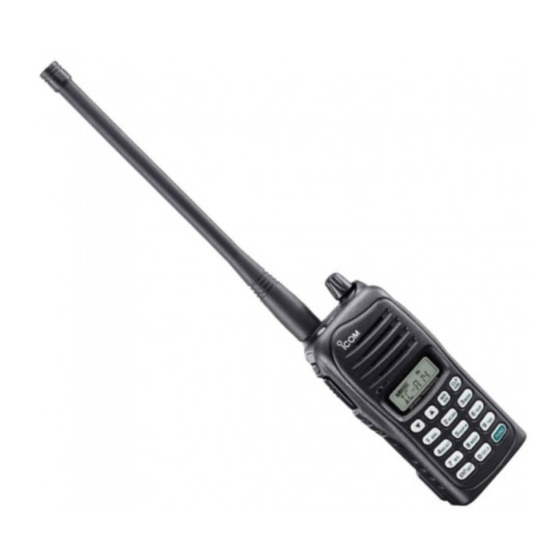
INSTRUCTION MANUAL
VHF AIR BAND TRANSCEIVER
iA14
iA14S
This device complies with Part 15 of the FCC
This device complies with Part 15 of the FCC
This device complies with Part 15 of the FCC
Rules. Operation is subject to the condition
Rules. Operation is subject to the condition
Rules. Operation is subject to the condition
that this device does not cause harmful inter-
that this device does not cause harmful inter-
that this device does not cause harmful inter-
ference.
ference.
ference.
YIC-A14
YIC-A14S
Advertisement
Table of Contents

Subscribe to Our Youtube Channel
Related Manuals for Icom IC-A14IC-A14S


Summary of Contents for Icom IC-A14IC-A14S
- Page 1 INSTRUCTION MANUAL VHF AIR BAND TRANSCEIVER iA14 iA14S This device complies with Part 15 of the FCC This device complies with Part 15 of the FCC This device complies with Part 15 of the FCC Rules. Operation is subject to the condition Rules.
-
Page 2: Safety Training Information
2.5 cm (1 inch) away from the body for exposure to humans: when transmitting and only use the Icom belt-clips which are listed on when transmitting and only use the Icom belt-clips which are listed on when transmitting and only use the Icom belt-clips which are listed on •... -
Page 3: Foreword
FOREWORD SUPPLIED ACCESSORIES Thank you for purchasing this Icom product. The IC-A14/S The following accessories are supplied with the transceiver. The following accessories are supplied with the transceiver. The following accessories are supplied with the transceiver. VHF AIR BAND TRANSCEIVER is designed and built with Qty. -
Page 4: Precaution
Icom Inc., could void your authority to containing a transmitter. containing a transmitter. -
Page 5: Table Of Contents
TABLE OF CONTENTS SAFETY TRAINING INFORMATION ������������ i 5. SCAN OPERATION ���������������� 18–20 ���������������� 18–20 ���������������� 18–20 n Scan types ���������������������18 ���������������������18 ���������������������18 FOREWORD����������������������� ii n COM band scan �������������������18 �������������������18 �������������������18 IMPORTANT����������������������� ii n Memory scan ��������������������19 ��������������������19 ��������������������19 EXPLICIT DEFINITIONS �����������������... -
Page 6: Panel Description
PANEL DESCRIPTION n Panel description q ANTENNA CONNECTOR [ANT] (p. 6) Connects the supplied antenna. w KEY LOCK SWITCH [ ] (p. 9) Push to turning the key lock function ON. Push to turning the key lock function ON. Push to turning the key lock function ON. - Page 7 PANEL DESCRIPTION u KEYPAD (Available with the IC-A14 only; pgs. 3, 4) !0 EXTERNAL SPEAKER AND MICROPHONE JACKS EXTERNAL SPEAKER AND MICROPHONE JACKS EXTERNAL SPEAKER AND MICROPHONE JACKS [MIC/SP] (p. 39) i MEMORY MODE/MEMORY WRITE KEY [MR]/[MW] Connects the optional speaker microphone or a headset onnects the optional speaker microphone or a headset onnects the optional speaker microphone or a headset Push to select memory mode.
- Page 8 PANEL DESCRIPTION D KEYPAD (Available with IC-A14 only) Inputs digit “1” for frequency input or memory Inputs digit “5” for frequency input or memory channel selection, etc. (pgs. 8, 12) channel selection, etc. (pgs. 8, 12) Inputs “1,” “Q,” or “Z” during memory name pro- ...
- Page 9 PANEL DESCRIPTION Inputs digit “9” for frequency input or memory channel selection, etc. (pgs. 8, 12) Inputs “9,” “W,” “X,” or “Y” during memory name programming. (p. 15) After pushing [FUNC], toggles scan tag setting ON and OFF. (p. 20) ...
-
Page 10: Function Display
PANEL DESCRIPTION n Function display y DUPLEX INDICATOR (IC-A14 only) (p. 24) Appears when the duplex function is activate. Appears when the duplex function is activate. Appears when the duplex function is activate. Blinks while setting the duplex frequency. Blinks while setting the duplex frequency. -
Page 11: Accessory Attachment
ACCESSORY ATTACHMENT D Antenna D Belt clip Insert the supplied antenna into the Conveniently attaches to your belt. antenna connector and screw down Attach the belt clip as described below. q Release the battery pack if it is attached. the antenna as shown at right. w Slide the belt clip in the direction of the arrow until the belt lide the belt clip in the direction of the arrow until the belt lide the belt clip in the direction of the arrow until the belt... -
Page 12: Accessory Attachment
ACCESSORY ATTACHMENT D Battery pack attachment Turn the transceiver power OFF with [VOL] before attach- ing or detaching the battery pack. Slide the battery pack in the direction of the arrow (q), then lock it with the battery release button. •... -
Page 13: Basic Operation
BASIC OPERATION n Setting a frequency [VOL] D Using [Y]/[Z] keys q Rotate [VOL] to turn power ON, then push [CLR] to se- lect the frequency mode when memory CH number or WX CH number appears on the function display. w Push [Y]/[Z] to set the desired frequency. -
Page 14: Setting A Squelch Level
BASIC OPERATION n Setting a squelch level n Lock function The transceiver has a noise squelch circuit to mute unde- The lock function prevents accidental frequency changes The lock function prevents accidental frequency changes The lock function prevents accidental frequency changes The lock function prevents accidental frequency changes sired noise while receiving no signal. -
Page 15: Receiving
BASIC OPERATION n Receiving CAUTION: Transmitting without an antenna may damage the transceiver. q Rotate [VOL] to turn the power ON. w Push [SQLZ] several times to open the squelch. Z] or q Set the desired frequency in COM band using Set the desired frequency in COM band using Set the desired frequency in COM band using •... -
Page 16: Side Tone Function
BASIC OPERATION n Side tone function n LCD backlight When using a headset , the The IC-A14/S has LCD backlight for convenience during The IC-A14/S has LCD backlight for convenience during The IC-A14/S has LCD backlight for convenience during (other manufacture’s products) transceiver outputs your transmitted voice to the headset night time operation. -
Page 17: Memory Operation
MEMORY OPERATION n Memory channel selection n Memory bank selection (20 channels × 10 banks; de- IC-A14 has 200 memory channels (Available with the IC-A14 only) and IC-A14S has 100 memory channels for stor- fault setting) A 200 of the IC-A14’s memory channels are divided into A 200 of the IC-A14’s memory channels are divided into A 200 of the IC-A14’s memory channels are divided into age of often-used frequencies. -
Page 18: Programming A Memory Channel
MEMORY OPERATION n Programming a memory channel Program often-used frequencies with the following instruc- • EXAMPLE: Programming WX-05 into memory channel 9 Programming WX-05 into memory channel 9 Programming WX-05 into memory channel 9 tions. in memory BANK 3. Push D For IC-A14 q Push [CLR] to select the frequency mode, if necessary. - Page 19 MEMORY OPERATION D For IC-A14S q Push [CLR] to select the frequency mode, if necessary. • EXAMPLE: Programming 123.450 MHz into memory Programming 123.450 MHz into memory Programming 123.450 MHz into memory w Set the desired frequency. (p. 8) channel 51. e Push and hold [MR] for 1 sec. to enter the select memory Push write mode.
-
Page 20: Memory Names
MEMORY OPERATION n Memory names For IC-A14 The memory channel can display an 8-character name in- t Push the appropriate digit key several times to select the stead of the programmed frequency. the appropriate digit key several times to select the the appropriate digit key several times to select the desired character as listed at left. -
Page 21: Memory Names N Copying Memory Contents
MEMORY OPERATION n Copying memory contents NOTE: When programming a memory name to the pro- This function copies a memory channel’s contents into the This function copies a memory channel’s contents into the This function copies a memory channel’s contents into the grammed memory channel, operate as follow. -
Page 22: Clearing The Memory Contents (Available With The Ic-A14 Only)
MEMORY OPERATION n Clearing the memory contents (Available with the IC-A14 only) Unwanted memory channels can be cleared. q Select the desired memory channel to be cleared. (p. 12) • Select the desired bank if desired. (p. 12) w Push [FUNC] then push and hold [CLR] for 1 sec. •... -
Page 23: Scan Operation
SCAN OPERATION n Scan types n COM band scan The IC-A14 has 3 scan types to suit your needs. IC-A14S q Push [CLR] to select the frequency mode. has 2 scan types. w Push [SQLY]/[SQLZ] to set the squelch level to the to set the squelch level to the to set the squelch level to the to set the squelch level to the... -
Page 24: Memory Scan
SCAN OPERATION n Memory scan n Weather channel scan (Available with the IC-A14 only) NOTE: Program 2 or more memory channels with “TAG” setting to start memory scan. q Push [FUNC], then push [WX](7) to select a weather to select a weather to select a weather q Push [MR] to select memory mode. -
Page 25: Weather Channel Scan (Available With The Ic-A14 Only)
SCAN OPERATION n “TAG” channel setting Memory and weather channels* can be specified to be For IC-A14S q Push [MR] to select memory mode. skipped for the memory and weather channel* scans re- w Select the desired memory channel to be a “TAG” chan- the desired memory channel to be a “TAG”... -
Page 26: Other Functions
OTHER FUNCTIONS n Home function n Accessing 121.5 MHz emer- gency frequency The home function is convenient if you want to return the transceiver to default condition without memory channels. (Available with the IC-A14 only) (Available with the IC-A14 only) (Available with the IC-A14 only) The following transceiver’s settings will return to the default value;... -
Page 27: Key Touch Beep Tone N Anl Function
OTHER FUNCTIONS n Key touch beep tone n ANL function The beep tone, which sounds at the push of a switch can be The ANL (Automatic Noise Limiter) function reduces noise The ANL (Automatic Noise Limiter) function reduces noise The ANL (Automatic Noise Limiter) function reduces noise set, if desired. -
Page 28: Weather Channel Operation (Available With The Ic-A14 Only)
OTHER FUNCTIONS n Weather channel operation (Available with the IC-A14 only) D Setting weather alert function The IC-A14 has VHF marine WX (weather) channel receiv- Setting weather alert function Setting weather alert function ing capability for flight planning. An NOAA broadcast station transmits a weather alert tone An NOAA broadcast station transmits a weather alert tone An NOAA broadcast station transmits a weather alert tone before any important weather announcements. - Page 29 OTHER FUNCTIONS n Duplex operation (Available with the IC-A14 only) The duplex function allows you to call a flight service station while receiving a VOR station. The duplex function requires frequency programming for the flight service station in ad- vance. D Programming a duplex frequency D Operating the duplex function Operating the duplex function...
-
Page 30: Set Mode Setting
OTHER FUNCTIONS n Set mode setting D Set mode items Set mode is used for programming infrequently changed val- ues or conditions of functions. • ANL— ANL function (available with IC-A14S only) (available with IC-A14S only) (available with IC-A14S only) Sets the ANL function that reduces function that reduces... - Page 31 OTHER FUNCTIONS • I.MIC— Internal microphone usage The internal microphone can be deactivated for headset op- eration. This setting prevents unwanted audio/noise transmission en- tering from the internal microphone with [PTT] operation. • TOT— Time-out timer Sets the time-out timer period for the prevention of pro- longed transmission, etc., according to regulatory require- longed transmission, etc., according to regulatory require- longed transmission, etc., according to regulatory require-...
-
Page 32: Battery Packs And Case
Icom radios or Icom charger. Only Icom battery cause an explosion. cause an explosion. cause an explosion. packs are tested and approved for use and charge with Icom R DANGER! NEVER solder the battery terminals or NEVER DANGER! NEVER DANGER! NEVER... -
Page 33: D Charging Caution
You may use the battery until the remaining capacity ing. You may use the battery until the remaining capacity temperature range: BC-179 . Icom (0˚C to +40˚C; +32˚F to +104˚F) is about half, then keep it safely in a cool dry place with the... -
Page 34: Charging The Battery
BATTERY PACKS AND CASE n Charging the battery D Regular charging with the BC-179+BC-174 CAUTION! • DO NOT modify the CP-22. A modification could cause a fire or modify the CP-22. A modification could cause a fire or modify the CP-22. A modification could cause a fire or The BC-179 provides regular charging of battery packs. - Page 35 BATTERY PACKS AND CASE D AD-106 installation D Rapid charging with the BC-119N+AD-106 Connect the BC-119N/BC-121N (q), then install the The optional BC-119N provides rapid charging of battery packs. The following are additionally required. AD-106 into the holder space of the BC-119N/BC-121N •...
-
Page 36: Battery Case (Optional For Some Versions)
BATTERY PACKS AND CASE D Rapid charging with the BC-121N+AD-106 n Battery case The optional BC-121N allows up to 6 battery packs to be (optional for some versions) charged simultaneously. The following are additionally re- quired. D Precaution • Six AD-106 charger adapters. NEVER incinerate used battery cells since internal battery incinerate used battery cells since internal battery incinerate used battery cells since internal battery... - Page 37 BATTERY PACKS AND CASE D Alkaline cells installation w Install 6 AA (LR6) size alkaline cells. Install 6 AA (LR6) size alkaline cells as described below. q Release the latch, and open the cover. • Install the conventional alkaline cells only. •...
-
Page 38: Battery Packs And Case
BATTERY PACKS AND CASE D Battery case attachment Slide the battery case in the direction of the arrow. To release the battery case: • Slide the battery case until the transceiver’s battery release button Slide out the battery case’s battery release button in the di- Slide out the battery case’s battery release button in the di- Slide out the battery case’s battery release button in the di- makes a ‘click’... -
Page 39: Cloning
CLONING Cloning allows you to quickly and easily transfer the pro- grammed data from one transceiver to another transceiver, or, data from PC to a transceiver using the optional CS-A14 or, data from PC to a transceiver using the optional CS-A14 cloning software. -
Page 40: Cloning
CLONING D Cloning using PC Data can be cloned to and from a PC ® ® ® ® (Microsoft Windows Windows using the optional CS-A14 2000/XP and Windows Vista™) and the optional OPC-478 CLONING SOFTWARE (RS-232C or OPC-478UC . Consult the type) (USB type) CLONING CABLE CS-A14... -
Page 41: Troubleshooting
TROUBLESHOOTING If your transceiver seems to be malfunctioning, please check the following points before sending it to a service center. PROBLEM POSSIBLE CAUSE SOLUTION REF. No power comes on. • The battery is exhausted. • Recharge the battery pack. pgs. 29–31 pgs. -
Page 42: Specifications
• Intermediate frequencies : 1st 46.35 MHz, 2nd 450 kHz IC-A14S • Sensitivity • Sensitivity • Sensitivity • Power supply requirement : Specified Icom’s battery packs COM band COM band COM band –6 dBµ typical (6 dB S/N) (6 dB S/N) (6 dB S/N) 7.4 V DC standard... -
Page 43: Options
OPTIONS D BATTERY PACKS D BELT CLIPS • MB-94 belt clip • BP-230N/BP-232N battery packs Li-Ion Alligator type belt clip. BP-230N: 7.4 V/980 mAh Li-ion battery pack. BP-232N: 7.4 V/2000 mAh Li-ion battery pack. • MB-96F leather belt hanger Attaches with the supplied belt clip (Fixed type). Attaches with the supplied belt clip (Fixed type). -
Page 44: Optional Headset Connection
OPTIONAL HEADSET CONNECTION D OPC-499 ( connection HEADSET ADAPTER) When using a headset (3rd party products) via the OPC-499 the transceiver outputs your transmitted voice HEADSET ADAPTER to the headset for monitoring. See “n Side tone function” (p. 11) when setting the side tone level. PTT switch Use a PTT switch with a 3.5 mm (... -
Page 45: For Class B Unintentional Radiators
FOR CLASS B UNINTENTIONAL RADIATORS This equipment has been tested and found to comply with the limits for a Class B digital device, pursuant to part 15 of the FCC Rules. These limits are designed to provide rea- sonable protection against harmful interference in a resi- dential installation. - Page 46 MEMO...
- Page 47 MEMO...
- Page 48 A-6631H-1EX-q Printed in Japan © 2007–2008 Icom Inc. 1-1-32 Kamiminami, Hirano-ku, Osaka 547-0003, Japan Printed on recycled paper with soy ink.
Need help?
Do you have a question about the IC-A14IC-A14S and is the answer not in the manual?
Questions and answers