
Related Manuals for Emerson Rosemount 1153 Series B


Summary of Contents for Emerson Rosemount 1153 Series B
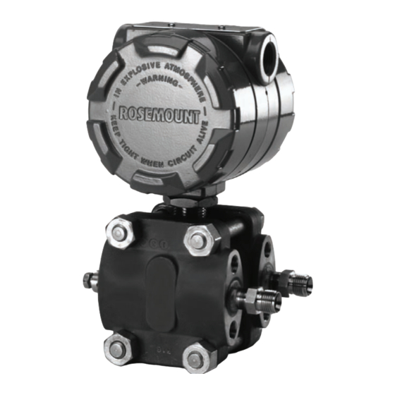
- Page 1 Reference Manual 00809-0100-4302, Rev BA January 2008 Rosemount 1153 Series B ® Alphaline Nuclear Pressure Transmitter Product Discontinued www.rosemountnuclear.com...
- Page 2 Please reference Table 6-2 (Rosemount 1153 Series B Spare Parts List) for the applicable part numbers.” Table 6-2, “Rosemount 1153 Series B Spare Parts List”, in all locations the following part numbers 4/13/12 are updated: Amplifier Circuit Board, Output Code R: “01154-0001-0005”...
- Page 3 Reference Manual 00809-0100-4302, Rev BA Rosemount 1153 Series B January 2008 Rosemount 1153 Series B ® Alphaline Nuclear Pressure Transmitter NOTICE Read this manual before working with the product. For personal and system safety, and for optimum product performance, make sure you thoroughly understand the contents before installing, using, or maintaining this product.
- Page 4 Chanhassen, MN 55317 IMPORTANT The Rosemount 1153 Series B Pressure Transmitter is designed for Nuclear Class IE usage, has been tested per IEEE Std 323-1974 and IEEE Std 344-1975 as defined in the Qualification Test Report 108025, and is manufactured to the requirements of NQA-1; 10CFR50, Appendix B quality assurance programs; and 10CFR Part 21.
- Page 5 Replaced amplifier circuit card with damping, output code R P/N 01154-0021-0002 with 01154-0021-0004 Throughout Throughout References to Fisher-Rosemount were changed to Emerson Process Management i, back cover Cover, i, iii and Web address changed from www.rosemount.com to www.rosemountnuclear.com back cover...
- Page 6 Reference Manual 00809-0100-4302, Rev BA Rosemount 1153 Series B January 2008...
-
Page 7: Table Of Contents
Reference Manual 00809-0100-4302, Rev BA Rosemount 1153 Series B January 2008 Table of Contents SECTION 1 Overview ..........1-1 About The Transmitter . - Page 8 Reference Manual 00809-0100-4302, Rev BA Rosemount 1153 Series B January 2008 Sensing Module Checkout........5-3 Disassembly Procedure.
- Page 9 Reference Manual 00809-0100-4302, Rev BA Rosemount 1153 Series B January 2008 TOC-3...
- Page 10 Reference Manual 00809-0100-4302, Rev BA Rosemount 1153 Series B January 2008 TOC-4...
-
Page 11: Overview
Rosemount 1153 Series B Transmitters are uniquely built for Class 1E nuclear service while retaining the working concept and design parameters of the Rosemount 1151 Series that have become a standard of reliable service. - Page 12 Reference Manual 00809-0100-4302, Rev BA Rosemount 1153 Series B January 2008...
-
Page 13: Overview
Reference Manual 00809-0100-4302, Rev BA Rosemount 1153 Series B January 2008 Section 2 Installation Overview ........page 2-1 General Considerations . -
Page 14: Mechanical Considerations
Read this section carefully before proceeding to the CONSIDERATIONS mechanical installation procedure. Mount the Rosemount 1153 Series B Transmitter to a rigid support (i.e. a support with a fundamental mechanical resonant frequency of 40 Hz or greater). A mounting bracket included with the transmitter facilitates panel mounting. - Page 15 Reference Manual 00809-0100-4302, Rev BA Rosemount 1153 Series B January 2008 The Swagelok tube fittings are shipped completely assembled for immediate use. Do not disassemble them before use; doing so may contaminate the fittings and result in leaks. Insert the tubing into the Swagelok tube fitting, making sure that the tubing rests firmly on the shoulder of the fitting and that the nut is finger tight.
-
Page 16: Conduit
Reference Manual 00809-0100-4302, Rev BA Rosemount 1153 Series B January 2008 The piping between the process and the transmitter must transfer the pressure measured at the process taps to the transmitter. Possible sources of error in this pressure transfer are: •... - Page 17 Rosemount 1153 Series B January 2008 The Rosemount 1153 Series B Pressure Transmitter provides a 4–20 mA signal when connected to a suitable dc power source. Figure 2-2 on page 2-5 shows a typical signal loop consisting of transmitter, power supply, and various receivers (controller, indicator, computer, etc.).
- Page 18 Reference Manual 00809-0100-4302, Rev BA Rosemount 1153 Series B January 2008 Figure 2-3. Transmitter Load Output Code P Limits. 4—20 mA DC 2000 1650 Qualified 1500 Region 1325 1000 Design Region 13.5 Power Supply (V DC) Output Code R 4—20 mA DC...
-
Page 19: Installation Procedures
Reference Manual 00809-0100-4302, Rev BA Rosemount 1153 Series B January 2008 INSTALLATION Installation consists of mounting the transmitter and conduit and making electrical connections. Procedures follow for each operation. PROCEDURES Mechanical Transmitter Be careful not to break the neck seal between the sensor module and the electronics housing. - Page 20 Reference Manual 00809-0100-4302, Rev BA Rosemount 1153 Series B January 2008 Figure 2-4. Typical Transmitter Mounting Bracket Configuration. Center of Gravity - Includes Bracket Center of Gravity is Centered in Lateral Direction (22.9) (25.4) 6.02 (153) 2.62 (66.5) (114.3) 2.81 (71.4)
- Page 21 Reference Manual 00809-0100-4302, Rev BA Rosemount 1153 Series B January 2008 Figure 2-5. Transmitter Dimensional Drawings. 1153DB AND 1153HB 4.5 Max. (114.3) 0.75 (19) clearance 4.5 Max. (114.3) for cover removal (typical) - 14 NPT Conduit Connection (2 Places) 9 Max.
-
Page 22: Conduit
Reference Manual 00809-0100-4302, Rev BA Rosemount 1153 Series B January 2008 Conduit Seal the conduit threads with thread sealant. (The transmitter conduit ™ seal interface was qualified using Grafoil tape.) Conduit threads mate with a standard –14 NPT male fitting. - Page 23 Reference Manual 00809-0100-4302, Rev BA Rosemount 1153 Series B January 2008 Figure 2-6. Transmitter Installation Configuration. LIQUID SERVICE Plugged Tee for Plugged Tees for Steam Service or Steam Service or Sealing Fluid Sealing Fluid Flow Blocking Valves Blocking Sufficient Valve...
-
Page 24: Electrical
Reference Manual 00809-0100-4302, Rev BA Rosemount 1153 Series B January 2008 Electrical Remove the cover from the terminal side of the transmitter (see Figure 2-5 on page 2-9). Connect the power leads to the “SIGNAL” terminals on the transmitter terminal block (see Figure 2-7 on page 2-12). Torque the terminal screws to 5 in-lb (0.6 N-m), or hand-tight. -
Page 25: Overview
Span Adjustment The span on any Rosemount 1153 Series B transmitter is continuously adjustable to allow calibration anywhere between maximum span and maximum span. For example, the span on a Range Code 4 transmitter can be continuously adjusted between 0–150 and 0–25 inH... -
Page 26: Calibration Procedures
100 125 150 Pressure (inH ➀ 500% Zero Suppression ➀ Graphs based on a Range Code 4 (0–25 to 0–150 inH Rosemount 1153 Series B with a calibrated span of 25 inH CALIBRATION PROCEDURES Zero and Span NOTE The Rosemount 1153 Series B Pressure Transmitter contains electronic Adjustment circuit boards which may be static sensitive. - Page 27 Reference Manual 00809-0100-4302, Rev BA Rosemount 1153 Series B January 2008 Figure 3-2. Zero and Span Adjustment Screws. Zero Span Example (for Range Code 4) Initial transmitter calibration: 25 to 125 inH (100 inH O span with zero suppressed 25 inH Desired transmitter calibration: –75 to –25 inH...
- Page 28 Reference Manual 00809-0100-4302, Rev BA Rosemount 1153 Series B January 2008 Adjust the zero to eliminate any existing zero elevation or suppression. With 0 inH O pressure applied to the transmitter, turn the zero adjustment until the output reads 4 mA. The unit is now calibrated for 0 to 100 inH Adjust the span to the desired new span.
- Page 29 Reference Manual 00809-0100-4302, Rev BA Rosemount 1153 Series B January 2008 Flux: Mil F 14256, Type A, Fed Spec QQ-S-571 Type RA. B1. Method (Output Code P with Switch) Locate the three-position slide switch on the component side of the amplifier board (see Figure 3-3).
-
Page 30: Linearity Adjustment
Reference Manual 00809-0100-4302, Rev BA Rosemount 1153 Series B January 2008 Figure 3-4. Jumper Wire Placement for “R” and “P” Output with Turrets. “R” OUTPUT AND “P” OUTPUT WITH TURRETS DETAIL A DETAIL B DETAIL C Moderate Elevation/Suppression (to Elevate Zero) -
Page 31: Damping Adjustment
Reference Manual 00809-0100-4302, Rev BA Rosemount 1153 Series B January 2008 Figure 3-5. Linearity and Damping Adjustment Damping Adjustment Electronics Side of (Optional) Transmitter Housing (Cover Removed) Linearity Adjustment Damping Adjustment Damping electronics are available as an option. Transmitters with standard... -
Page 32: Correction For High Line Pressure (Rosemount 1153Db And 1153Hb Only)
Reference Manual 00809-0100-4302, Rev BA Rosemount 1153 Series B January 2008 Correction For High Line Span Pressure (Rosemount If a differential transmitter is calibrated with the low side at ambient pressure 1153DB and 1153HB but will be used at high line pressure, correct the span adjustment to Only) compensate for the effect of static pressure on the unit. -
Page 33: Zero
Reference Manual 00809-0100-4302, Rev BA Rosemount 1153 Series B January 2008 Calculate full-scale adjustment correction in terms of pressure: 0.9 % 300 inH 2.7 inH Repeat step 4 with the results of step 7: 2.7 inH -------------------------------------------------------------- - 0.675 % span... - Page 34 Reference Manual 00809-0100-4302, Rev BA Rosemount 1153 Series B January 2008 Using standard calibration procedures, calibrate the unit to the required span, with the 4 mA or zero point corresponding to zero differential pressure: 4 mA at 0 inH O and 20 mA at 400 inH...
-
Page 35: Overview
The block diagram in Figure 4-2 on page 4-3 illustrates the operation of the transmitter. OPERATION Rosemount 1153 Series B Alphaline Pressure Transmitters have a variable capacitance sensing element, the δ-Cell (Figure 4-1 on page 4-2). Differential capacitance between the sensing diaphragm and the capacitor plates is converted electronically to a 2-wire 4–20 mA dc signal. - Page 36 Reference Manual 00809-0100-4302, Rev BA Rosemount 1153 Series B January 2008 is the capacitance between the high pressure side and the sensing diaphragm. is the capacitance between the low pressure side and the sensing diaphragm. -------------------- – Where: is the current source.
-
Page 37: The Δ-Cell Sensor
Reference Manual 00809-0100-4302, Rev BA Rosemount 1153 Series B January 2008 Figure 4-2. Electrical Block Diagram. Current Demodulator Sensor Detector – Test Current Limiter Oscillator Signal Curr. Osc. Control Reverse Voltage Control Amp. Polarity Regulator Amp. Protection Current Control ™... -
Page 38: Voltage Regulator
Reference Manual 00809-0100-4302, Rev BA Rosemount 1153 Series B January 2008 An integrated circuit amplifier is used as a feedback control circuit and controls the oscillator drive voltage such that: -------------------- – VOLTAGE REGULATOR The transmitter uses a zener diode, transistor, and resistors to provide a constant voltage of 6.4 V dc for the reference and 7 V dc for the oscillator. -
Page 39: Overview
(see “Important Notice” on page 6-10 and Important Notice at the beginning of this manual preceding the Table of Contents). The Rosemount 1153 Series B has no moving parts and requires a minimum of scheduled maintenance. Calibration procedures for range adjustment are outlined in Section 3: Calibration. -
Page 40: Test Terminals
Numbers in parentheses refer to item numbers in Figure 5-2 on page 5-4. NOTE The Rosemount 1153 Series B Pressure Transmitter contains electronic circuit boards which may be static sensitive. You can easily check the printed circuit boards (5 and 6) for a malfunction by substituting spare boards into the circuit. -
Page 41: Sensing Module Checkout
Numbers in parentheses refer to item numbers in Figure 5-2 on page 5-4. PROCEDURE NOTE The Rosemount 1153 Series B Pressure Transmitter contains electronic circuit boards which may be static sensitive. Process Flange Removal Process O-rings may retain some process fluid after disassembly of process flanges. - Page 42 Clean isolating diaphragms with a soft rag and a mild cleaning solution. Do not use any chlorine or acid solutions to clean the diaphragms. Rinse diaphragms with distilled water. Figure 5-2. Typical Rosemount 1153 Series B, Exploded View. Flange Module...
-
Page 43: Electrical Housing Disassembly
Reference Manual 00809-0100-4302, Rev BA Rosemount 1153 Series B January 2008 Table 5-1. Rosemount 1153 Parts List. Part Description Part Description Electronics Cover Metal O-Ring for Process Flange O-Ring for Electronics Cover Sensor Module Electronics Housing Process Flange Header Assembly Board... -
Page 44: Reassembly Procedure
Numbers in parentheses refer to item numbers in Figure 5-2 on page 5-4. PROCEDURE NOTE The Rosemount 1153 Series B Pressure Transmitter contains electronic circuit boards which may be static sensitive. Preliminary Replace the cover O-rings (2) whenever you remove a cover. Clean... -
Page 45: Electrical Housing Reassembly
Reference Manual 00809-0100-4302, Rev BA Rosemount 1153 Series B January 2008 Electrical Housing Replace the zero and span adjustment screw O-rings (19) whenever you remove the zero and span adjustment screws (16). Lightly grease Reassembly the O-rings with Dow Corning 55 Silicone O-ring Grease (Rosemount P/N 01153-0248-0001 or P/N 01153-0053-0001). -
Page 46: Process Flange Reassembly
Reference Manual 00809-0100-4302, Rev BA Rosemount 1153 Series B January 2008 Process Flange Replace the metal O-rings (11) with new O-rings if the flanges were removed. Reassembly Carefully place an O-ring (11) in the isolator well of the high side (“H”) of the sensing module. -
Page 47: Post Assembly Tests
Reference Manual 00809-0100-4302, Rev BA Rosemount 1153 Series B January 2008 POST-ASSEMBLY TESTS Conduct hydrostatic testing to 150% of maximum working pressure or 2,000 psi, whichever is greater. Calibrate the transmitter per the calibration section of this manual. Conduct nuclear cleaning to 1 ppm chloride content of transmitter “wetted parts.”... - Page 48 Reference Manual 00809-0100-4302, Rev BA Rosemount 1153 Series B January 2008 Table 5-2. Troubleshooting. Symptom Potential Source Corrective Action High Output Primary Element Check for restrictions at primary element, improper installation or poor condition. Note any changes in process fluid properties that may affect output.
- Page 49 Reference Manual 00809-0100-4302, Rev BA Rosemount 1153 Series B January 2008 Erratic Output Loop Wiring Do not use over 100 volts to check the loop, or damage to the transmitter electronics may result. Check for inadequate voltage to the transmitter.
- Page 50 Reference Manual 00809-0100-4302, Rev BA Rosemount 1153 Series B January 2008 5-12...
-
Page 51: Nuclear Specifications
Reference Manual 00809-0100-4302, Rev BA Rosemount 1153 Series B January 2008 Section 6 Specifications and Reference Data Nuclear Specifications ......page 6-1 Performance Specifications . -
Page 52: Both Output Codes
Reference Manual 00809-0100-4302, Rev BA Rosemount 1153 Series B January 2008 Steam Pressure/Temperature Accuracy within ±(4.5% of upper range limit + 3.5% of span) during and after sequential exposure to steam at the following temperatures and pressures: 318 °F (158.9 °C), 73 psig for 8 hours 265 °F (129.5 °C), 24 psig for 56 hours... -
Page 53: Performance Specifications
Reference Manual 00809-0100-4302, Rev BA Rosemount 1153 Series B January 2008 PERFORMANCE Based on zero-based ranges under reference conditions. SPECIFICATIONS Accuracy ±0.25% of calibrated span; includes combined effects of linearity, hysteresis, and repeatability Dead Band None Drift ±0.2% of upper range limit for 30 months Temperature Effect Range Codes 4–9:... - Page 54 Reference Manual 00809-0100-4302, Rev BA Rosemount 1153 Series B January 2008 Static Pressure Zero Effect Rosemount 1153DB: Per 1,000 psi (6.89 MPa): Range Code Static Pressure Zero Effect 4, 5 ±0.2% of upper range limit 3, 6–8 ±0.5% of upper range limit Rosemount 1153HB: Per 1,000 psi (6.89 MPa):...
-
Page 55: Functional Specifications
Reference Manual 00809-0100-4302, Rev BA Rosemount 1153 Series B January 2008 FUNCTIONAL Service SPECIFICATIONS Liquid, gas, or vapor Output 4–20 mA dc Power Supply Design limits are as shown in Figure 2-3 on page 2-6. See qualification report 108025 for additional detail. - Page 56 Reference Manual 00809-0100-4302, Rev BA Rosemount 1153 Series B January 2008 Pressure Ranges Rosemount 1153DB and 1153HB: Range Code Pressure Ranges 0–5 to 0–30 inH 0 (0–1.24 to 0–7.46 kPa) (D units only) 0–25 to 0–150 inH O (0–6.22 to 0–37.3 kPa) 0–125 to 0–750 inH...
-
Page 57: Physical Specifications
Reference Manual 00809-0100-4302, Rev BA Rosemount 1153 Series B January 2008 Overpressure Limits Rosemount 1153GB AND 1153AB: Operates within specifications from 0.5 psia (3.4 kPa abs) to upper range limit. Overpressure limits without damage to the transmitter: Range Code Overpressure Limit 3–8... -
Page 58: Ordering Information
Typical Model Number: 1153DB 4 RA (1) The Rosemount 1153 Series B with Output Code R Electronics is also available with adjustable damping. This option is specified by adding “N0037” to the end of the complete model number, for example, 1153DB4RAN0037. -
Page 59: Spare Parts
Reference Manual 00809-0100-4302, Rev BA Rosemount 1153 Series B January 2008 Table 6-2. Rosemount 1153 Series B Spare Parts Order Number Item No. Qty. Spare Parts Part Description (Fig 5-2) Req’d Category Model 1153GB Model 1153DB Model 1153AB Model 1153HB... -
Page 60: Important Notice
NOTES: “R” Electronics boards (set of 2) are interchangeable with “P” electronics boards (set of 2). Rosemount 1153 Series B spare parts are not hydrostatic tested or nuclear cleaned. Part numbers shown may differ from those currently supplied. The part numbers shown are current at the time of printing of this manual, but may be revised in the future. - Page 61 Reference Manual 00809-0100-4302, Rev BA Rosemount 1153 Series B January 2008 Index ....3-9 ..3-8 Adjustment High Line Pressure Removing Sensor Module .
- Page 62 Reference Manual 00809-0100-4302, Rev BA Rosemount 1153 Series B January 2008 Index-2...
- Page 64 Reference Manual 00809-0100-4302, Rev BA January 2008 The Emerson logo is a trade mark and service mark of Emerson Electric Co. Rosemount, the Rosemount logotype, and Alphaline are registered trademarks of Rosemount, Inc. Cell is a trademarks of Rosemount, Inc.
Need help?
Do you have a question about the Rosemount 1153 Series B and is the answer not in the manual?
Questions and answers