Advertisement
Quick Links
Instruction Manual
D102600X012
January 2018
Type EZR Pressure Reducing Regulator
161aY SERIES PILOT
!
Failure to follow these instructions or
to properly install and maintain this
equipment could result in an explosion
and/or fire causing property damage and
personal injury or death.
Fisher™ regulators must be installed,
operated and maintained in accordance
with federal, state and local codes, rules
and regulations and Emerson Process
Management Regulator Technologies, Inc.
(Emerson) instructions.
If the regulator vents gas or a leak
develops in the system, service to the unit
may be required. Failure to correct trouble
could result in a hazardous condition.
Call a gas service person to service the
unit. Only a qualified person must install
or service the regulator.
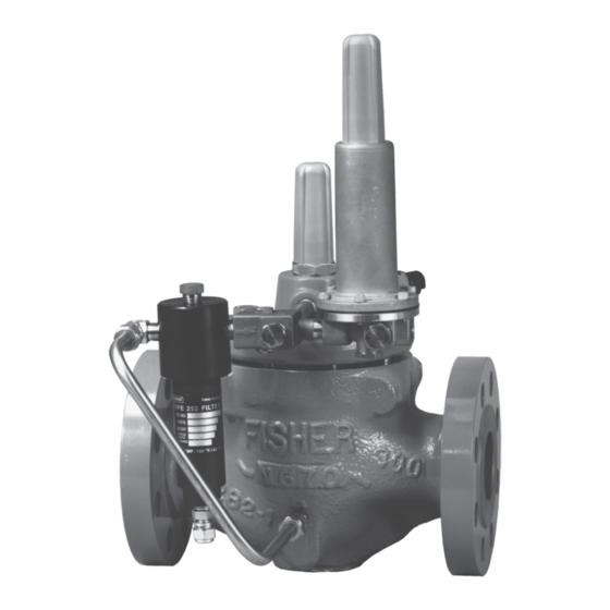
Figure 1. Type EZR Pressure Reducing Regulator
WaRnIng
TYPE EZR REgULaTOR
Introduction
Scope of the Manual
This instruction manual provides installation,
startup, adjustment, maintenance and parts ordering
information for Type EZR pressure reducing regulator,
Types 112 restrictor, 161AY, 161EB and
PRX Series pilot. Any accessories used with this
regulator are covered in their respective
instruction manuals.
Product Description
The Type EZR pilot-operated, pressure reducing
regulators are used for natural gas, air or other
non-corrosive gas applications and include a
Type 112 restrictor and a 161EB, 161AY or PRX Series
pilot. For applications that have high-pressure drops,
using a Type 161AYM or 161EBM monitor pilot will
increase the accuracy of the regulator.
Type EZR
TYPE PRx PILOT
Advertisement

Related Manuals for Fisher EZR Series


Summary of Contents for Fisher EZR Series
- Page 1 Type EZR pressure reducing regulator, personal injury or death. Types 112 restrictor, 161AY, 161EB and PRX Series pilot. Any accessories used with this Fisher™ regulators must be installed, regulator are covered in their respective operated and maintained in accordance instruction manuals.
-
Page 2: Specifications
Type EZR Specifications Specifications for the Type EZR regulator are shown below. The control spring range for the pilot is marked on the spring case of 161EB Series pilots and on the nameplate of 161AY and PRX Series pilots. Other information for the main valve appears on the nameplate. Main Valve Body Sizes, End Connection Styles Minimum and Maximum Differential Pressures and Structural Design Ratings See Tables 4 and 10 (1)(2) - Page 3 Type EZR Table 1. Main Valve Body Sizes, End Connection Styles and Body Ratings STRUCTURaL DESIgn MaIn VaLVE BODY SIZE, nPS / Dn MaIn VaLVE BODY MaTERIaL EnD COnnECTIOn STYLE RaTIng NPT (NPS 2 x 1 and 2 / DN 50 x 25 and 50 only) 400 psig / 27.6 bar 2 x 1, 2, 3, 4 and 6 / Cast iron CL125 FF 200 psig / 13.8 bar...
-
Page 4: Principle Of Operation
Type EZR Table 4. Main Valve Minimum Differential Pressures MInIMUM DIFFEREnTIaL, PERCEnT OF CagE CaPaCITY MaIn VaLVE MaIn SPRIng PaRT FOR 90% CaPaCITY FOR 100% CaPaCITY DIaPHRagM BODY SIZE, nUMBER anD MaTERIaL 100% Trim 60% Trim 30% Trim 100% Trim 60% Trim 30% Trim nPS / Dn... - Page 5 Type EZR 161EB SERIES PILOT 161aY SERIES PILOT TYPE 112 RESTRICTOR TYPE 252 PILOT SUPPLY FILTER FLOW DIRECTIOn MaIn SPRIng B2625_2 DIaPHRagM anD PLUg aSSEMBLY W7438_07/2008 TYPE EZR WITH TYPES 161EB PILOT, 112 RESTRICTOR anD 252 FILTER TYPE PRx PILOT TYPE 252 SUPPLY FILTER RESTRICTOR DaMPER...
- Page 6 Type EZR BLOCK VaLVE BLOCK VaLVE InLET OUTLET HanD VaLVE SUPPLY PRESSURE LInE COnTROL LInE aLTERnaTE COnTROL LInE RESTRICTOR B2605_A 161 SERIES PILOT 161 SERIES SIngLE PILOT InSTaLLaTIOn WITH PILOT ExHaUST InTO COnTROL LInE BLOCK VaLVE BLOCK VaLVE InLET OUTLET PILOT ExHaUST HanD VaLVE...
-
Page 7: All Installations
Type EZR all Installations 300 x 150) are different than EW valve bodies and are not interchangeable. The robust design of the Type EZR allows this regulator Install trims only in correct restricted to be installed indoors or outdoors. When installed trim bodies. - Page 8 Type EZR BLOCK VaLVE DOWnSTREaM BLOCK VaLVE UPSTREaM REgULaTOR REgULaTOR InLET OUTLET HanD VaLVE SUPPLY SUPPLY PRESSURE RESTRICTOR PRESSURE LInE LInE COnTROL 161 SERIES RESTRICTOR 161 SERIES PILOT LInE PILOT HanD VaLVE aLTERnaTE COnTROL LInE COnTROL LInE 161 SERIES WIDE-OPEn MOnITORIng SYSTEM InSTaLLaTIOn BLOCK VaLVE DOWnSTREaM BLOCK VaLVE...
- Page 9 Type EZR DOWnSTREaM UPSTREaM REgULaTOR BLOCK VaLVE REgULaTOR BLOCK VaLVE OUTLET InLET HanD TYPE PRx TYPE PRx VaLVE PILOT PILOT SUPPLY SUPPLY PRESSURE PRESSURE LInE LInE PILOT HanD ExHaUST VaLVE COnTROL LInE aLTERnaTE COnTROL LInE TYPE PRx WIDE-OPEn MOnITORIng SYSTEM InSTaLLaTIOn WITH PILOT ExHaUST TO InTERMEDIaTE PRESSURE WORKIng BLOCK VaLVE BLOCK VaLVE...
- Page 10 Type EZR TYPE PRx/120 TYPE PRx/120 PILOT TYPE PRx/125 PILOT PILOT FILTER FILTER InLET InTERMEDIaTE OUTLET M1001_05/2016 InLET PRESSURE TYPE PRx: OUTLET PRESSURE S- SUPPLY PORT aTMOSPHERIC PRESSURE B- BLEED PORT LOaDIng PRESSURE L- LOaDIng PORT a - SEnSIng PORT InTERMEDIaTE PRESSURE Figure 5.
-
Page 11: Startup And Adjustment
Type EZR between the first and second Type EZR regulators. Connect the “A” port of upstream Type PRX-125 pilot downstream of both regulators. The pilot supply pressure connection for the downstream Type EZR regulator must be directly upstream of the Type EZR using intermediate pressure and connected to the “S” port of the downstream Type PRX-120. Install a Type 252 pilot supply filter upstream of the pilot, if needed, to keep the supply source from clogging the restrictor in the pilot. Inspect and clean this filter regularly to make sure it has not been plugged. Connect the loading port (Port L) of the W4559_1 downstream Type PRX-120 pilot to the bonnet of the Figure 6. - Page 12 Type EZR Table 5. 161EB Series Pilot Adjustment Recommendations RECOMMEnDED TYPE 112 RESTRICTOR TYPE 112 RESTRICTOR SETTIngS TO aVOID PILOT TYPE SETTIngS FOR LOW FLOW OPERaTIOn aT LOW FLOW Avoid restrictor setting of “2” or less if continuous 161EB Series Pilots Restrictor Setting of “5” or greater flows are expected to be less than 5% of maximum capacity Note: Higher Type 112 restrictor settings will increase proportional band. Adjustment of the Type 112 restrictor will also cause a shift in setpoint. Setpoint should be checked and adjusted following restrictor setting adjustment. Table 6.
- Page 13 Type EZR Table 8. Diaphragm Material Selection Information 17E68 17E97 17E88 nITRILE (nBR) nITRILE (nBR) FLUOROCaRBOn (FKM) Gas Temperature (for lower temperatures -20 to 150°F / -29 to 66°C 0 to 150°F / -18 to 66°C 0 to 260°F / -18 to 127°C contact your local Sales Office) Best for high pressure conditions, i.e. Best for natural gas having aromatic transmission service or high pressure General Applications Best for cold temperatures.
- Page 14 Type EZR Table 10. Main Valve Maximum Pressure Ratings, Diaphragm Selection Information and Main Spring Selection MaxIMUM MaxIMUM MaxIMUM OPERaTIng EMERgEnCY InLET OPERaTIng InLET BODY SIZE DIaPHRagM MaIn SPRIng DIaPHRagM DIFFEREnTIaL anD DIFFEREnTIaL PRESSURE nPS / Dn MaTERIaL COLOR CODE DESIgnaTIOn PRESSURE PRESSURE...
- Page 15 Type EZR LOaDIng COnnECTIOn: 1/4 nPT PIPE COnnECTS TO TYPE EZR DIaPHRagM LOaDIng PORT PILOT SUPPLY COnnECTIOn: 1/4 nPT PIPE COnnECTS TO UPSTREaM PILOT SUPPLY TaP OUTLET COnnECTIOn: 1/4 nPT PIPE COnnECTS TO PILOT InLET COnnECTIOn OPTIOnaL LOaDIng COnnECTIOn: 11B5004-A 1/4 nPT nORMaLLY PLUggED TYPE 112 COnTROL LInE COnnECTIOn:...
-
Page 16: Maintenance
Remove all trim parts from the main valve and clean the body interior. Then follow procedure in Assembly CaUTIOn section to convert a Fisher E-body to a Type EZR. avoid personal injury or damage to CaUTIOn property from sudden release of pressure... - Page 17 Type EZR Table 12. Troubleshooting Guide PROBLEM POSSIBLE SOLUTIOn Outlet pressure suddenly rises above • If travel indicator is in UP position, check restrictor and pilot supply filter for plugging setpoint and approaches inlet pressure • If travel indicator is in DOWN position, check main valve for debris or diaphragm damage • Check main valve inlet strainer for plugging • Check inlet pressure at high flow condition Outlet pressure normal at low flow but • Check sizing calculations to be sure main valve body is large enough for load falls below setpoint at high flow • Check for undersized or restricted control line (use the minimum size given in step 6 of All Installations of the Type EZR Installation section). • Adjust restrictor to a lower setting • Adjust restrictor to a higher setting Outlet pressure cycles • ...
- Page 18 (key 130) from the bottom plug. Make sure to use a Type EZR 3. R emove the bottom plug (key 11) and the bottom bonnet. The Type EZR bonnet is nOT plug O-ring (key 10). interchangeable with other Fisher™ 4. Remove the diaphragm (key 9). E-body bonnets. Installing an improper bonnet can result in stem assembly 5. Remove the top plug O-rings (keys 14 and 70).
- Page 19 Type EZR InDICaTOR FITTIng MaIn SPRIng UPPER SPRIng (KEY 19) (KEY 12) SEaT (KEY 17) InDICaTOR STEM O-RIng (KEY 18) (KEY 15) HEx nUTS (KEY 4) InDICaTOR COVER (KEY 21) BaCK-UP RIngS InDICaTOR (KEY 16) WaSHER (KEY 79) O-RIng (KEY 6) (nPS 6 / Dn 150 SIZE OnLY) InDICaTOR WaSHER (KEY 20)
- Page 20 Type EZR 9. C heck the indicator fitting O-ring (key 6). Lubricate and replace if necessary. 10. To replace travel indicator parts, lubricate all O-rings, back-up rings and threads. To reassemble, hold the indicator stem (key 15) and place the parts on the stem in the following order (see Figure 10). • Washer (key 79 for NPS 6 / DN 150 size only) • Main Spring (key 12), small end first ...
- Page 21 Type EZR the diaphragm assembly (key 7). If used, make sure BODY SEaL O-RIng (KEY 11) the diaphragm limiter is installed beveled side up on BaCK-UP RIng (KEY 50) Types 161EB and 161EBM pilots with 200 to 350 psig / 13.8 to 24.1 bar outlet pressure range. BODY (KEY 1) Lightly apply lubricant to the control spring seat.
- Page 22 Type EZR procedure steps 1 and 4 and pull the stem out of the PRx Series Maintenance diaphragm casing (key 4). CaUTIOn 7. I nstall the stem (key 14) into the guide insert (key 18) and perform Body Area Maintenance procedure steps 6 through 8 as necessary. always remove spring compression before performing maintenance on this unit.
-
Page 23: Parts Ordering
Type EZR 4. R emove restrictor adjusting screw with hole (key 32). Remove and inspect O-ring (key 28) for damage or wear and replace if necessary. Lightly lubricate O-ring before placing on the adjusting screw. Insert restrictor adjusting screw into the body (key 16) and completely tighten. Insert ring nut (key 30) and completely tighten. Back out restrictor adjusting screw 1/2 turn. note Figure 13. Pushing Groove Valve Up With Retainer When using a Type PRx/120 pilot with a Type PRx/125 pilot as a monitor, use the 4. R emove machine screws (key 10) from lower cover following settings: (key 21) and the separate lower cover from the body ... - Page 24 Type EZR Table 14. Type EZR Main Valve Body Part Numbers (key 1, Figure 14) BODY STYLE BODY SIZE, BODY EnD COnnECTIOn Standard nPS / Dn MaTERIaL STYLE Tapped Inlet and Tapped Outlet (Included Tapped Inlet) GE11581X012 GE32046X012 GE11440X012 - - - - - - - - - - - CL150 RF ...
-
Page 25: Parts List
Type EZR Table 14. Type EZR Main Valve Body Part Numbers (key 1, Figure 14) (continued) BODY STYLE BODY SIZE, EnD COnnECTIOn BODY MaTERIaL Standard nPS / Dn STYLE Tapped Inlet and Tapped Outlet (Included Tapped Inlet) CL150 RF GE19084X012 - - - - - - - - - - - CL300 RF ... - Page 26 Type EZR Description Part number Description Part number Quick Change Travel Indicator Kit (Included are O-ring (continued) keys 4, 6, 12, 15, 16, 17, 18, 19, 20, 21 and 22) (continued) NPS 3 / DN 80 body NPS 2 / DN 50 Nitrile (NBR) 10A8931X012 Yellow Spring, Nitrile (NBR) O-rings 29B0243X112 Fluorocarbon (FKM) 10A8931X052 Yellow Spring, Fluorocarbon (FKM) O-rings 29B0243X122 ...
- Page 27 Type EZR Description Part number Description Part number O-ring Top Plug O-ring (continued) NPS 1, 1-1/4 x 1, 2 x 1 and 2 / DN 25, 32 x 25, NPS 3, 4, 6 x 4 and 8 x 4 / DN 80, 100, 50 x 25 and 50 bodies 150 x 100 and 200 x 100 bodies Nitrile (NBR) 1E216306992 Nitrile (NBR) 10A3803X062 Fluorocarbon (FKM) 1L949306382 Fluorocarbon (FKM) 10A3803X032...
- Page 28 Type EZR Description Part number Description Part number 21 Indicator Cover, Plastic 66 O-ring (NPS 8 x 6 / DN 200 x 150 body only) NPS 1, 1-1/4 x 1, 2 x 1 and 2 / DN 25, 32 x 25, Nitrile (NBR) 18A2556X022 50 x 25 and 50 bodies T14188T0012 Fluorocarbon (FKM) 18A2556X032 NPS 3, 4, 6 x 4 and 8 x 4 / DN 80, 100, O-ring 150 x 100 and 200 x 100 bodies 19B2270X012 ...
- Page 29 Type EZR Description Part number Description Part number 129 Socket Head Screw, Stainless steel O-ring (Type 161EBM) 10A0904X012 For NPS 1, 1-1/4 x 1 and 2 x 1 / DN 25, 32 x 25 38 Lower Spring Seat 18B1248X012 and 50 x 25 only 1D6170X0012 130 Lock Washer, Stainless steel Type 161aY or 161aYM Pilot (Figure 20) For NPS 1, 1-1/4 x 1 and 2 x 1 / DN 25, 32 x 25 and 50 x 25 only 1A329128982 131 ...
- Page 30 Type EZR For Working Monitor Set Description Part number Post Seal Description Part number Nitrile (NBR) 1D687506992 Fluorocarbon (FKM) 1N430406382 4 Nut, SA194 (2 required) 1C3306X0832 49 Connector Seal Pipe Nipple, Plated Steel Nitrile (NBR) 13A1584X012 NPS 1 and 1-1/4 x 1 / Fluorocarbon (FKM) 13A1584X022 ...
- Page 31 Type EZR Pounds to Pounds (161EB Series Pilots) PRx Series Pilots (Figure 26) Monitor System Mounting Parts (Figure 23) Description Part number Parts Kits Description Part number Elastomer Parts Kits (includes keys: 4, 5, 14, 17, Pipe Nipple, Plated steel 18, 25 and 28) NPS 1 and 1-1/4 / DN 25 and 32 bodies - - - - - - - - - - - Nitrile (NBR) RPRX00X0N12...
- Page 32 Type EZR 48B2142 B2617_2 MaIn VaLVE aSSEMBLY FOR nPS 1, 1-1/4 x 1, 2 x 1, 2, 3, 4, 6 x 4 anD 8 x 4 / Dn 25, 32 x 25, 50 x 25, 50, 80, 100, 150 x 100 anD 200 x 100 BODY SIZES (nOTE: SEE nPS 2 x 1 / Dn 50 x 25 aSSEMBLY FOR aDDITIOnaL PaRTS) Figure 14.
- Page 33 Type EZR TOP PLUg (KEY 5) O-RIng (KEY 14) O-RIng (KEY 70) DIaPHRagM (KEY 9) BOTTOM PLUg (KEY 11) O-RIng (KEY 10) 19B2408 LOCK WaSHER (KEY 130) SOCKET HEaD SCREW (KEY 129) nPS 1, 1-1/4 x 1 anD 2 x 1 / Dn 25, 32 x 25 anD 50 x 25 DIaPHRagM aSSEMBLY 49B5067 MaIn VaLVE aSSEMBLY FOR nPS 6, 8 x 6 anD 12 x 6 /...
- Page 34 Type EZR 40C3570-C aPPLY LUBRICanT (L) PaRTS nOT SHOWn: 63 MaIn VaLVE aSSEMBLY FOR nPS 8 / Dn 200 BODY Figure 14. Type EZR Main Valve (continued)
- Page 35 Type EZR B2617_A2 Figure 15. Type EZR Nameplate and Flow Arrow B2617_C B2617_D Figure 16. Type EZR Restricted Trim Figure 17. Type EZR Cage O-ring Placement B2617_E nPS 1, 1-1/4 x 1, 2 x 1, 2, 3 anD 4 / nPS 6 x 4, 8 x 4, 6, 8 x 6, 12 x 6 / Dn 25, 32 x 25, 50 x 25, 50, 80 anD 100 BODY SIZES Dn 150 x 100, 200 x 100, 150, 200 x 150, 300 x 150 BODY SIZES...
- Page 36 Type EZR 37B1193 TYPE 161EB PILOT TYPE 161EBM PILOT 37B1199 aPPLY LUBRICanT (L) SEnSE (COnTROL) PORT SEnSE 31B5012-A (ExHaUST) PORT TYPE 161EBM PILOT Figure 19. 161EB Series Pilots Table 15. 161EB Series Pilot Part Numbers (keys 7, 8, 9, 10 and 11, Figure 19) OUTLET (COnTROL) PRESSURE RangE anD SPRIng COLOR CODE Type 161EB or 161EBM Type 161EB...
- Page 37 Type EZR TYPE 161aY B2631 B2632 B2631 TYPE 161aYM Figure 20. Types 161AY and 161AYM Pilots...
- Page 38 Type EZR 20B4393-A aPPLY LUBRICanT Figure 21. Type 112 Restrictor TYPE 252 nPS 1 / Dn 25 OnLY TYPE PRx TYPE 161aY TYPE 112 OR 161aYM 41B3471 TYPE PRx PILOT 40C1205 nOTE: TYPE 161aY PILOT 1 nPS 4 / Dn 100 BODY OnLY MOUnTIng FOR nPS 1 THROUgH 4 / MOUnTIng FOR nPS 1 THROUgH 6 / Dn 25 THROUgH 100 TYPE EZR REgULaTOR...
- Page 39 Type EZR B2612 Figure 23. Pounds to Pounds (161EB Series Pilots) Working Monitor Mounting Parts PILOT TYPE 399a OR EZR TYPE 161EB OR 161EBM TYPE 112 TYPE 252 TYPE 161aYM 41B5009 37B8952 Figure 24. Pounds to Inches (161AY/161EB Series Pilots) Figure 25.
- Page 40 Emerson Automation Solutions The Emerson logo is a trademark and service mark of Emerson Electric Co. All other marks are the property of their prospective owners. Fisher™ is a mark owned by Fisher Controls International LLC, a Americas Asia Pacific business of Emerson Automation Solutions.
Need help?
Do you have a question about the EZR Series and is the answer not in the manual?
Questions and answers