Table of Contents
Advertisement
Instruction Manual
Form 1203
February 2000
Type 667 Diaphragm Actuator Sizes 30-76 and 87
Contents
. . . . . . . . . . . . . . . . . . . . . . . . . . . . . . . . .
. . . . . . . . . . . . . . . . . . . . . . . . . . . . .
. . . . . . . . . . . . . . . . . . . . . . . . . . . . . . . . . .
. . . . . . . . . . . . . . . . . . . . . . . . . . . . . . .
. . . . . . . . . . . . . . . . . . . . . . . . . . . . . . . . . .
. . . . . . . . . . . . . . . . . . . . . . . . . .
. . . . . . . . . . . . . . . . . . . . . . . . . . . . . . . .
. . . . . . . . . . . . . . . . . . . . . . . . . . . . . . . . . . . .
. . . . . . . . . . . . . . . . . . . . . . . . . .
Handwheel (70, 76, & 87)
. . . . . . . . . . . . . . . .
. . . . . . . . . . . .
. . . . . . . . . . . . . . . . . . . . . .
. . . . . . . . . . . . . . . . .
. . . . . . . . . . . . . .
. . . . . . . . . . .
. . . . . . . .
. . . . . . . . . . . . . . . . . . . . . .
. . . . . . . . . . . . . . . . . . . . . . .
. . . . . . . . . . . . . . . . . . . . . .
. . .
. . . . . .
. . . . . . . . . . . . .
. . . . . . . . . . . . . . . . . . . . . .
. . . . . . . . . . . . . . . . . . . . . . .
. . . . . . . . . . .
. . . . . . . . . . . . . . . .
. . . . . . . . . . . . . . . .
. . . . . . . . . . . . . . . .
Type 667 Size 30-76 & 87
2
2
2
3
3
3
4
5
6
6
6
7
8
8
8
9
9
9
W1916-1*/IL
10
10
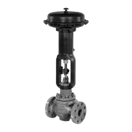
Figure 1. Type 667 or 667-4 Actuator Mounted
11
13
. . . . . . . . . . . . . . . . . . . . . . . . . . . . . . . . . . .
13
13
. . . . . . . . . . . . . . . . . . . . . . . . . . . . . . . . . . .
14
14
Side-Mounted Handwheel (30-60)
14
16
R
on easy-e
Valve
. . . . . . . .
. . . . . . . . .
. . . . . . . . . . . . . . . . . . . . . . . . .
. . . . . . . . . . . . . . . . . . . . . . . . . .
. . . . . . . . . . . . . . . . . . . .
. . . . . . . . . . . .
. . . . . . . . . . . . . . . .
17
17
17
17
17
17
25
28
. . . . . .
31
31
Advertisement
Table of Contents

Related Manuals for Fisher 667


Summary of Contents for Fisher 667
-
Page 1: Table Of Contents
Form 1203 Type 667 Size 30-76 & 87 February 2000 Type 667 Diaphragm Actuator Sizes 30-76 and 87 Contents Introduction ....... . . -
Page 2: Introduction
1. These values also apply to the Type 667-4 actuator construction. 2. Actuator travel may be less than the value listed after connected to the valve. 3. Maximum actuator travel for Type 667-4 is 102 mm (4 inches). 4. See also the Specification portion of the introduction section. -
Page 3: Specifications
Installation Specifications Key number locations are shown in figures 6, 7, and 8, Refer to table 1 for Specifications of the Type 667 and unless otherwise noted. Also, refer to figure 3 for loca- tion of parts. 667-4 actuators. See the actuator nameplate for spe- cific information for your actuator. -
Page 4: Mounting The Actuator On The Valve
Type 667 Size 30-76 & 87 you perform the Bench Set Spring Adjustment proce- VENT NPT FEMALE CONNECTION (TOP LOADING) dures in this section to confirm that the actuator is ad- DIAPHRAGM CASINGS justed correctly for the valve travel. D Positioner: If a positioner is installed, or is to be... -
Page 5: Discussion Of Bench Set
Type 667 Size 30-76 & 87 NOTES: THE LOWER PSIG LOADING PRESSURE (MARKED ON NAMEPLATE) WHERE THE FIRST MOVEMENT OF SPRING ACTUATOR STEM IS DETECTED. ADJUSTER MARK THIS POINT WITH TAPE OR A MARKER. THE UPPER PSIG LOADING PRESSURE RETRACTS ACTUATOR STEM. -
Page 6: Bench Set Spring Adjustment
Bench Set Spring Adjustment duce a slightly different span than specified. Contact The term “bench set” means that the actuator is not your Fisher Controls sales office or sales representa- connected to the valve, or any other loads. Ensure that tive for assistance. -
Page 7: Installing The Stem Connector Assembly
Contact diameter of that stem. Damage to your Fisher Controls sales office or sales representa- threads on either stem or in the stem tive for assistance. -
Page 8: Deadband Measurement
Because of the care Fisher ment, a ‘‘jump” movement, or oscillating movements of Controls takes in meeting all manufacturing require- the actuator during automatic loop control. -
Page 9: Actuator
Type 667 Size 30-76 & 87 control signal to the actuator. Be sure construction, also remove the piping or tubing from the the actuator cannot suddenly open or connection in the upper diaphragm casing (key 1). close the valve. 2. Turn the spring adjuster (key 74) counterclockwise... -
Page 10: Top-Mounted Handwheel Assembly (Adjustable Down Travel Stop)
Type 667 Size 30-76 & 87 3. Fill the seal bushing with lubricant (key 237 or 10. After the last bolt is tightened to 27 NSm equivalent), slide the bushing into the yoke (key 73), (20 lbfSft), all of the bolts should be tightened again to and install the snap ring (key 72). -
Page 11: Assembly For Top-Mounted Handwheel
Type 667 Size 30-76 & 87 D Remove the cap and take out the cotter pin. Re- D Remove the hex nuts and cap screws (keys 14 move the castle nut, bearing retainer, thrust bearing, and 13, figures 6, 7, and 8) from the diaphragm cas- and races (keys 247, 167, 166, 180, and 181). - Page 12 Type 667 Size 30-76 & 87 14. Refer to the Assembly portion of the Actuator CAUTION maintenance section. For size 70 and 87 actuators handwheels (figure Over-tightening the diaphragm cap 12): screws and nuts (keys 13 and 14) can Refer to figure 12 for top-mounted handwheel assem- damage the diaphragm.
-
Page 13: Side-Mounted Handwheel Assembly For Size 34 Through 60 Actuators
Type 667 Size 30-76 & 87 7. Tighten the remaining bolts in a clockwise, criss- 4. Remove the screw (key 161) and pointer mounting bolt (key 159, not shown) located behind the pointer cross pattern to 13 NSm (10 lbfSft). -
Page 14: Side-Mounted Handwheel Assembly For Size 70, 76, And 87 Actuators
Type 667 Size 30-76 & 87 hex nuts (keys 170 and 147) to hold the handwheel 74), thrust bearing (key 128), and the pinned adjusting assembly in position. Cap screws (key 163) should be screw (key 131) will come out with the actuator stem. - Page 15 Type 667 Size 30-76 & 87 8. The lower sleeve (key 123) has a milled groove in Note one end. Coat the sleeve threads with lubricant (key 239 or equivalent), slide the end of the lower sleeve When you replace actuator diaphragms...
-
Page 16: Casing-Mounted Travel Stops
Type 667 Size 30-76 & 87 23. After the last bolt is tightened to 27 NSm (20 lbfSft), 2. Bypass the control valve, reduce loading pressure to atmospheric, and remove the tubing or piping from all of the bolts should be tightened again to 27 NSm the connection in top of the yoke (key 73, figures 6, 7, (20 lbfSft) in a circular pattern around the bolt circle. -
Page 17: Parts Kits
Each actuator has a serial number stamped on the O-ring material is nitrile, and gasket nameplate. Always mention this number when corre- material is composition. sponding with your Fisher Controls sales office or sales representative regarding technical information or Description Part Number replacement parts. - Page 18 Type 667 Size 30-76 & 87 Description Part Number Qty Description Part Number Qty Upper Diaphragm Plate Screw, Cap, hex hd Aluminum [93°C (200°F) maximum] Standard Handwheel, travel stop style 13, adj. Size 30 31B2028X012 Up stop style 14, for: Sizes 34 &...
- Page 19 Type 667 Size 30-76 & 87 PARTIAL VIEW OF TOP LOADED TYPE 667 ACTUATOR SIZES 30 THROUGH 60 50A8378-C APPLY LUBRICANT OR SEALANT 50A8379-C/IL Figure 6. Type 667 Actuator Sizes 30 through 60...
- Page 20 Type 667 Size 30-76 & 87 APPLY LUBRICANT 50A8598-E / IL Figure 7. Type 667 Size 70 and 76 Actuator Description Part Number Qty Description Part Number Qty Stem Connector Assembly (steel, zn pl) Stem Connector Assembly (steel, zn pl) (Con’t.)
- Page 21 Type 667 Size 30-76 & 87 APPLY LUBRICANT 50A8600-E / IL Figure 8. Type 667 Size 87 Actuator Description Part Number Qty Description Part Number Qty Disk, Travel Indicator (SST) Disk, Travel Indicator (SST) (Cont’d) Standard w/Side-Mounted Handwheel Sizes 30 & 34...
- Page 22 Sizes 70 & 87 to 76 mm (3-in.) travel 1N131524092 Sizes 70 & 87 Type 667-4 11A3811X012 Standard or w/Side-Mtd Handwheel Sizes 70 & 87 Type 667-4 w/Handwheel 1N886924392 Size 70 & 87 w/102 mm (4-in.) Travel 1V7826X0012 Sizes 70, 76, & 87...
- Page 23 Type 667 Size 30-76 & 87 APPLY LUBRICANT NOTE: THE TOP MOUNTED HANDWHEEL IS NOT DESIGNED FOR USE UNDER HEAVY LOAD OR FREQUENT USE. 30B3940-C / IL Figure 9. Top-Mounted Handwheel Assembly for Size 30 through 40 Actuators Description Part Number Qty...
- Page 24 Type 667 Size 30-76 & 87 APPLY LUBRICANT 30B3942-A Figure 10. Top-Mounted Handwheel Assembly, Style P2 for Size 45, 50, 60, and 76 Actuators Description Part Number Qty Description Part Number Qty Actuator Stem (Chromium-Plated Steel) Actuator Stem (Chromium-Plated Steel) (continued)
-
Page 25: Top-Mounted Handwheel
Type 667 Size 30-76 & 87 Description Part Number Qty Description Part Number Qty Lubricant, Lubriplate MAG-1 Mounting Plate or equivalent Cast Iron not furnished with actuator - - - Sizes 30 to 40 1F116519042 Sizes 45 to 60 & 76... - Page 26 Type 667 Size 30-76 & 87 APPLY LUBRICANT 33B9224-B / IL Figure 11. Top-Mounted Handwheel Assembly for Size 45-76 Actuators...
- Page 27 Type 667 Size 30-76 & 87 APPLY LUBRICANT CV8060-J / IL Figure 12. Top-Mounted Handwheel Assembly for Size 70 and 87 Actuators...
- Page 28 Type 667 Size 30-76 & 87 APPLY LUBRICANT 30A8778-D / IL Figure 13. Side Mounted Handwheel Assembly for Size 34 and 40 Actuators Description Part Number Qty Description Part Number Qty Lubricant, Anti-Seize Lub-3 - - - Ball Never-Seez or equivalent...
- Page 29 Type 667 Size 30-76 & 87 APPLY LUBRICANT 40A8779-D / IL Figure 14. Side-Mounted Handwheel Assembly for Size 45 and 60 Actuators Description Part Number Qty Description Part Number Qty Handwheel Screw Lever Pivot Pin (416 SST) Bronze Sizes 34 & 40...
- Page 30 Type 667 Size 30-76 & 87 PART NOT SHOWN: 57 APPLY LUBRICANT 50A8604-F / IL Figure 15. Size 70, 76, and 87 Actuator with Side Mounted Handwheel Assembly...
-
Page 31: Side-Mounted Handwheel
Type 667 Size 30-76 & 87 Description Part Number Qty Cap Screw (pl steel) Sizes 34 & 40 1C403824052 Sizes 45 to 60 1A344424052 U-Bolt (steel) Sizes 34 & 40 1F657724092 Sizes 45 to 60 1F155524092 Guide Bolt (416 SST) Sizes 34 &... - Page 32 Type 667 Size 30-76 & 87 APPLY LUBRICANT APPLY LUBRICANT 38A1212-B / IL 28A1208-B / IL Figure 17. Style 11 Up Or Down Travel Stop Figure 18. Style 12 Up Travel Stop (Casing Mounted) (Casing Mounted) Description Part Number Qty...
- Page 33 Type 667 Size 30-76 & 87 AV8096-B / IL APPLY LUBRICANT 28A1204-B / IL Figure 20. Style 14 Up Travel Stop Figure 19. Style 13 Up Travel Stop (Casing Mounted) (Casing Mounted),size 30 shown Description Part Number Qty Nut, Hex (steel, zn pl)
- Page 34 - - - - - - - - - - - - - - - 10A2426X012 - - - - - - - - - - - - - - - 1E7246X0022 1. For Type 667-4, part number is 17A2270X012.
- Page 35 Yellow Black 1. Other spring selections are available by contacting your Fisher Controls sales office or sales representative. 2. 1-1/8 inch travel is available for size 34, and 1-1/2 inch travel is available for size 40 only. 3. For size 40 only.
- Page 36 2. For style 11 travel stops. 3. Type 667-4. easy-e, Fisher, Fisher-Rosemount, and Managing The Process Better are marks owned by Fisher Controls International, Inc. or Fisher-Rosemount Systems, Inc. All other marks are the property of their respective owners. EFisher Controls International, Inc. 1980, 2000; All Rights Reserved The contents of this publication are presented for informational purposes only, and while every effort has been made to ensure their accuracy, they are not to be construed as warranties or guarantees, express or implied, regarding the products or services described herein or their use or applicability.
Need help?
Do you have a question about the 667 and is the answer not in the manual?
Questions and answers