Table of Contents
Advertisement
Type 399A-161-112
T T y y p p e e 3 3 9 9 9 9 A A P P i i l l o o t t - - O O p p e e r r a a t t e e d d
P P r r e e s s s s u u r r e e - - R R e e d d u u c c i i n n g g R R e e g g u u l l a a t t o o r r
Contents
Contents
. . . . . . . . . . . . . . . . . . . . . . . . . . . . . . .
. . . . . . . . . . . . . . . . . . . . . . . . . . . . .
. . . . . . . . . . . . . . . . . . . . . . . . . . . . . . .
. . . . . . . . . . . . . . . . . . . . . . . . . . . . . . . .
. . . . . . . . . . . . . . . . . . . . . . . . . . . . . .
. . . . . . . . . . . . . . . . . . . . . . . . . .
. . . . . . . . . . . . . . . . . . . . . . . . . . . . .
. . . . . . . . . . . . . . . . . . . . . . . . . . . . . . .
. . . . . . . . . . . . . . . . . . . . . . . . . . . .
. . . . . . . . . . . . . . . . . . . . . . . . . . . . . . .
. . . . . . . . . . . . . . . . . . . . . . . . .
. . . . . . . . . . . . . . . . . . . . . . . . . . . . . . .
. . . . . . . . . . . . . . . . . . . . . . . . . .
. . . . . . . . . . . . . . . . . . . . . . . . . . . . . . .
. . . . . . . . . . . . . . . . . . . . . . . . . .
. . . . . . . . . . . . . . . . . . . . . . . . . . . . . . .
. . . . . . . . . . . . . . . . . . . . . . . . . .
Fisher, Fisher-Rosemount, and Managing The Process Better are marks owned by
Fisher Controls International, Inc. or Fisher-Rosemount Systems, Inc.
All other marks are the property of their respective owners.
EFisher Controls International, Inc. 1992, 1996; All Rights Reserved 3/96
. . . . . . . . . . . . . . . . . . . . . . . . . .
. . . . . . . . . . . . .
. . . . . . . . . . . . . . . .
. . . . . . . . . . . . . . . .
. . . . . . . . . . . . . . . . . . .
. . . . . . . . . . . . .
. . . . . . . . . . . . . . . . . . .
. . . . . . . . . . . . . . . . . .
. . . . . . . . . . . . . . . . . . . . . .
. . . . . . . . . . . . . . . . .
. . . . . . . . . . . . . . . . . .
. . . . . . . . . . . . . . . . . . . . . . .
. . . . . . . . . . . . . . . . . . . . . . . .
2
2
2
3
5
5
14
15
15
15
15
15
16
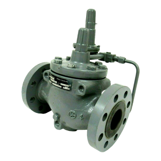
W6524/IL
Figure 1. Type 399A Easy Joe
16
Type 161 Pilot and Type 112 Restrictor
16
18
18
19
. . . . . . . . . . . . . . . . . . . . . . . . . . . . . . . . .
21
22
22
22
22
23
23
23
Type 161Y or 161YM Pilot
24
24
Pilot Mounting Parts
24
25
Instruction Manual
Form 5321
Regulator with a
R
. . . . . . . . . . . . . . . . . . . . . . . . . . .
. . . . . . . . . . . . . . . . . . . . . .
. . . . . . . . . . . . . . . . . . . . . . . .
. . . . . . . . . . . . . . . . . . . . . .
. . . . . . . . .
. . . . . . . . . . . . . . . . . .
. . . . . . . . . . . . . . . . . . . . . . . . . .
. . . . . . . . . . . . . . . . . . . . .
. . . . . . . . . . . . . . . . . . . . .
25
25
25
32
32
37
37
38
38
40
Advertisement
Table of Contents

Subscribe to Our Youtube Channel
Related Manuals for Fisher 399A
![Controller Fisher] 3660 Instruction Manual](https://static-data2.manualslib.com/product-images/3ac/1225055/60x60/fisher-3660-controller.jpg)


Summary of Contents for Fisher 399A
-
Page 1: Table Of Contents
..... Fisher, Fisher-Rosemount, and Managing The Process Better are marks owned by Fisher Controls International, Inc. or Fisher-Rosemount Systems, Inc. - Page 2 Form 5321, March 1996 The pilot for the Type 399A regulator has been changed from a Type 161Y and 161YM to a Type 161AY and 161AYM. The Type 161AY is a direct replacement for the Type 161Y and the Type 161AYM replaces the Type 161YM. The pilot is used for set pressure ranges of 6-inches w.c.
- Page 3 Type 399A-161-112 • Replace the Type 161Y or 161YM information in "Table 3. Outlet (Control) Pressure Ranges and Typical Proportional Bands" on page 4 with the following information: . c . . c . . c . o l l •...
- Page 4 Type 399A-161-112 • Replace the Type 161Y and 161YM Pilot Maintenance section beginning on page 23 with the following: Type 161AY or 161AYM Pilot Key numbers are referenced in figure 23. Body Area 1. Remove the cap screws (key 2) and separate the diaphragm casing (key 4) from the body (key 1).
- Page 5 Type 399A-161-112 6. To replace the lever assembly (key 16), remove the machine screws (key 17). To replace the stem (key 14) or access the stem seal O-ring (key 30) also perform Body Area Maintenance procedure steps 1 and 4, and pull the stem out of the diaphragm casing (key 4).
- Page 6 Type 399A-161-112 The Type 161AYM to the Type 161AY: New part required: key 27 1. Insert pipe plug (key 27) in the diaphragm casing (key 4). 2. Follow steps 1 through 3, and 6 through 8 in the Disassemble/Reassemble section of Diaphragm and Spring Case Area Maintenance of this errata sheet to remove the stem seal O-ring (key 30).
- Page 7 Type 399A-161-112 • Replace "Figure 23. Types 161Y and 161YM Pilots" on page 38 with the following: B2631 TYPE 161AY PILOT ASSEMBLY BODY SEAL O-RING (KEY 11) BACKUP RING (KEY 50) BODY (KEY 1) EXPANDED VIEW OF BODY AREA SHOWING THE BODY SEAL O-RING AND BACKUP RING PLACEMENT Figure 23.
- Page 8 Type 399A-161-112 B2631_A TYPE 161AYM PILOT ASSEMBLY B2632 TYPE 161AY AND 161AYM PILOT EXTERIOR ASSEMBLY Figure 23. Type 161AY and 161AYM Pilot Assemblies...
-
Page 9: Introduction
(250 to 600 Type 161—Downstream pressure range from 5 to 300 psig/17.2 to 41.4 bar) for the Type 399A or for other psig (0.34 to 21 bar). Pilot bleed exhausts downstream appropriate applications. The modification utilizes a through the sense (control) line. -
Page 10: Specifications
[34.5 1. Rating and end connections for other than ANSI standards, such as, DIN standards, can usually be provided; consult the Fisher sales office or sales representative. 2. The main valve body and bonnet are designed to withstand an inlet pressure of up to 1480 psig (102.0 bar). However, the main valve diaphragm should be inspected if inlet pressure exceeds 1050 psig (72.4 bar). - Page 11 Type 399A-161-112 Table 3. Outlet (Control) Pressure Ranges and Typical Proportional Bands U.S. UNITS, INCHES OF WATER METRIC UNITS, BAR COLUMN OR PSIG PILOT CONTROL SPRING PILOT CONTROL SPRING PILOT Typical Outlet (Control) Outlet (Control) TYPE Proportional Typical Proportional Pressure Range...
-
Page 12: Installation
3. Partial coat E55 diaphragm at maximum 100_F (66_C). 6-inch size rated at 800 psig (55 bar). Installation Installation All Installations When properly installed and maintained, a Type 399A WARNING regulator normally bleeds no gas to atmosphere while operating, allowing it to be installed in a pit or other Personal injury, equipment damage, or enclosed location without an elaborate venting system. - Page 13 6, 8 x 6 or 12 x 6 0.68 0.14 1. For additional information on percent travels at lower differential, and the corresponding capacity, consult your Fisher sales office or sales representative. 2. Minimum differential with motion indicator removed. 1. Only personnel qualified through training and...
- Page 14 Type 399A-161-112 Table 6. 161 Series Pilot Pressure Ratings MAXIMUM INLET MAXIMUM OUTLET PRESSURE FOR TYPE PRESSURE FOR TYPE 161, 161Y , 161H, 161EB OR 161, 161Y , 161H OR 161EB 161EBH PILOT BODY AND DIAPHRAGM OR 161EBH TYPE SPRING...
- Page 15 Type 399A-161-112 21B5005-A 21B5006-A 11B5004-A C0805/IL Figure 3. Installation Schematics...
- Page 16 Type 399A-161-112 CONTROL LINE UPSTREAM UPSTREAMOF BLOCK VALVE B 161-112 TYPE 399A-161- TYPE 399A-161EB 161EB-112 CONTROL LINE DOWNSTREAM DOWNSTREAMOF BLOCK VALVE B TYPE 399A-161- 161-112 TYPE 399A-161EB 161EB-112 CONTROL LINE DOWNSTREAM DOWNSTREAMOF BLOCK VALVE B TYPE 399A-161Y 161Y- - 112...
- Page 17 Type 399A-161-112 CONTROL LINE DOWNSTREAM DOWNSTREAMOF BLOCK VALVE B TYPE 399A 161 161 112 TYPE 399A-161EB 161EB-112 CONTROL LINE DOWNSTREAM DOWNSTREAMOF BLOCK VALVE B TYPE 399A-161YM 161YM-112 43B8213 A/IL Typical Single Regulator Installation Figure 3. Installation Schematics (Continued) remote, safe location away from air in- 5.
- Page 18 Type 399A-161-112 UPSTREAM UPSTREAM CONTROL LINE OF BLOCK VAL VE B TYPE 399A- 161 161 -112 AND TYPE 399A- 161- 161- 112 TYPE 399A- 161EB 161EB -112 AND TYPE 399A- 161EB- 161EB- 112 DOWNSTREAM DOWNSTREAM CONTROL LINE OF BLOCK VAL VE B...
- Page 19 Type 399A-161-112 CONTROL LINES DOWNSTREAM DOWNSTREAMOF BLOCK VALVE B 161M-112 AND TYPE 399A-161 161-112 TYPE 399A-161M TYPE 399A-161EBM 161EBM-112 AND TYPE 399A-161EB 161EB-112 CONTROL LINES DOWNSTREAM DOWNSTREAMOF BLOCK VALVE B 33B8215-A/IL TYPE 399A-161YM 161YM-112 AND TYPE 399A-161Y 161Y-112 Typical Wide-Open Upstr...
- Page 20 10 psig (0.69 bar) 28 psig (1.9 bar) 1. When using different sized regulators or a combination of Type 399A and other elastomeric style regulators, you must add the minimum pressure drop for each regulator to determine the total drop across the station.
-
Page 21: Wide-Open Monitor Installations
2. A wide-open monitoring installation using Type phragm being held in a full open position for extended 399A regulators should be arranged so that the up- periods of time, potentially causing the diaphragm to stream regulator is the working regulator and is set at take a ‘‘set’’, is eliminated. -
Page 22: Working Monitor Installations
Type 399A-161-112 Working Monitor Installations 1. Follow the procedures in the All Installations sec- tion, and then continue with step 2 of this section. 2. On working monitor installations, the working monitor regulator is always upstream and acts as a first-stage regulator by using the working pilot during normal operation. -
Page 23: Shutdown For Both Single-Regulator And Monitoring Installations
(figure 5). Inlet pressure bleeding through the be inspected periodically and replaced as necessary. Type 112 restrictor provides loading pressure to keep Due to the care Fisher takes in meeting all manufac- the Type 399A diaphragm tightly shut off. turing requirements (heat treating, dimensional toler- ances, etc.), use only replacement parts manufactured... - Page 24 PILOT INLET SPRING PILOT ST ATIC CONTROL LINE AND PILOT\ PILOT BLEED SUPPL Y (EXHAUST) PRESSURE LINE MOTION INDICA TOR TYPE 399A DIAPHRAGM SPRING TYPE 399A DIAPHRAGM SUPPORT TYPE 399A DIAPHRAGM INLET PRESSURE LOADING PRESSURE OUTLET (CONROL) PRESSURE PILOT EXHAUST 40B46386-C...
-
Page 25: Type 399A Main Valve
Type 161H, 161EBH 32B0710-A 32B0711-A A6794/IL Figure 5. Principle of Operation Schematic (Continued) Type 399A Main Valve WARNING Trim Parts Avoid personal injury or damage to prop- Instructions are given for complete disassembly and erty from sudden release of pressure or assembly. -
Page 26: Disassembly
Type 399A-161-112 Note The regulator may remain in the pipeline during maintenance procedures unless the main valve body (key 1) is replaced or removed for repairs. Disassembly 1. Remove the cap screws (key 3). Pry up the bonnet (key 2) from the body (key 1), as shown in figure 6. - Page 27 Type 399A-161-112 Table 9. Maintenance Tips PROBLEM POSSIBLE SOLUTION (SEE FIGURE 5 FOR PARTS LOCATION) Outlet pressure suddenly rises above set If motion indicator is in up position, check restrictor and pilot supply filter for plugging point and approaches inlet pressure...
-
Page 28: Assembly
Type 399A-161-112 Assembly 1. Apply lubricant (key 27) to all O-rings and gaskets before installing them. 2. As shown in figure 13, install the inlet strainer (key 23) or shim (key 23) then the cage O-ring (key 8) into the body (key 1). With a 1-1/4 x1, 1-1/2 x 1-inch body size, install the orifice adapter and orfice adapt- er O-ring (keys 76 &... -
Page 29: Motion Indicator Assembly
Type 399A-161-112 Motion Indicator Assembly Motion indicator assembly key numbers are refer- enced in figure 18. The indicator assembly can be re- moved and installed without removing the bonnet (key 2) from the body (key 1). 1. Remove the indicator protector (key 22), indicator stem guide (key 19), and indicator scale (key 21). -
Page 30: Type 161Y Or 161Ym Pilot
Type 399A-161-112 bly (key 7). Make sure that, if used, the diaphragm limiter is installed beveled side up. Sparingly apply lu- bricant to the control spring seat. 7. Install the spring case (key 2) on the body (key 1) with the vent (key 18) oriented to allow for wrenches, needed for connecting outlet piping, and to prevent clogging or entrance of moisture. -
Page 31: Type 161H, 161Hm, 161Ebh Or 161Ebhm Pilot
Type 399A-161-112 (key 15) with Lubriplate lubricant or equivalent and 13. Install a replacement closing cap gasket (key 35), install it on the valve stem (key 13). if necessary, and then install the closing cap (key 3). 6. Install the valve stem (key 13) into the lower casing... -
Page 32: Type 112 Restrictor
(key 13) and, using a crisscross pattern, torque them to 5 to 7 foot-pounds (7 to 9 N m)for When corresponding with your Fisher sales office or stainless steel constructions and 2 to 3 foot-pounds (3 sales representative about this equipment, always ref- to 4 N m)for aluminum constructions. - Page 33 Type 399A-161-112 Description Part Number Description Part Number Bonnet (cont’d) Cage O-Ring, nitrile rubber For 2 x 1-inch body 30B4342X022 For 1-inch body 14A5713X012 For 2 and 4 x 2-inch body For 1-1/4 x 1-inch body 14A5713X012 Cast iron, 2-inch only...
- Page 34 22B2811X042 22B2812X042 22B2813X042 22B2814X042 Key 15, 16, 17, 18, 19, 20 and 21. Motion Indicator Parts for Type 399A Main Valve BODY SIZE DESCRIPTION 1, 1-1/4 x 1, 1-1/2 x 1, 2, 4, 6, 6 x 4, 8 x 4, 3-inch 2 x 1 &...
- Page 35 Type 399A-161-112 APPL Y LUB 40B4415 G/IL Figure 18. Type 399A Main Valve Sizes: 1, 2, 3, 4, 6-inches...
- Page 36 Type 399A-161-112 APPL Y LUB PARTS NOT SHOWN: 29, 30, 33, 63 44B8883-A C0802 Figure 18. Type 399A Main Valve 1-1/4 x 1 and 1-1/2 x 1-Inch (Continued)
- Page 37 Type 399A-161-112 APPL Y LUB PARTS NOT SHOWN: 29, 30, 33, 63 44B2268-A C0803/IL Figure 18. Type 399A Main Valve 2 x 1-Inch (Continued)
- Page 38 Type 399A-161-112 SIZE 6, 8 X 6, & 12 X 6 ONL Y 31B5011-C C0804/IL Figure 18. Type 399A Main Valve (Continued) Description Part Number Description Part Number O-ring, For 8 x 6-inch body Seat Ring Adapter Nitrile 1D269206992 For 1-1/4 x 1-inch body...
-
Page 39: Type 112 Restrictor
Type 399A-161-112 20B4393 A/IL Figure 19. Type 112 Restrictor Type 112 Restrictor (figure 19) Description Part Number Description Part Number Pipe Plug, S31600 stainless steel 1A767535072 Plug/Stem Assembly, Lubricant (not furnished) nitrile w/stainless steel stem 20B9389X052 Dow Corning 33, 1 gal. (3.8 1) can... - Page 40 Type 399A-161-112 BLEED (EXHAUST) PORT SENSE PORT (CONTROL) PORT 31B5012-A TYPE 161M AND 161EBM PORT OUT PORT (CONTROL) TYPE 161EB GAUGE OR OPTIONAL (CONTROL) PORT APPL Y LUB TYPE 161 30B4395-E CO806/IL Figure 20. Type 161, 161M, 161EB and 161EBM...
- Page 41 Type 399A-161-112 BLEED (EXHAUST) PORT SENSE (CONTROL) PORT 32B0708-B IN PORT TYPE 161HM AND 161EBHM IN PORT OUT PORT (CONTROL) TYPE 161EBH GUAGE OR OPTIONAL OUT (CONTROL) PORT TYPE 161H APPL Y LUB 32B0707-B C0808/IL Figure 21. Type 161H, 161HM, 161EBH...
- Page 42 Type 399A-161-112 Keys 7, 8, 9, 10, and 11. Pilot Control Spring Range Parts (To Change Pilot Spring range) for Type 161, 161M, 161H and 161HM Pilots For 5 TO 15 PSIG (0.34 TO 1.0 BAR) For 10 TO 125 PSIG (0.69 TO 8.6...
- Page 43 Type 399A-161-112 Key 7. Pilot Control Spring Range Parts (To Change Pilot Spring range) for 161EB Series Pilots For 5 TO 15 PSIG (0.34 TO 1.0 BAR) For 10 TO 40 PSIG (0.69 TO 2.75 CONTROL SPRING RANGE BAR) CONTROL...
-
Page 44: Type 161, 161H 161M, 161Hm And 161Eb Series Pilot Mounting Parts
Type 399A-161-112 Description Part Number 11 Machine Screw, pl steel (2 req’d) For aluminum or brass disk assy, pl steel 1A331928982 For stainless steel disk assy, S30400 stainless steel 1A866435042 13 Valve Stem For Type 161Y For aluminum or brass disk assy, brass... -
Page 45: Mounting Parts
Type 399A-161-112 31B5010 A TYPE 161YM TYPE 161Y 31B3786 C CO807/IL Figure 23. Type 161Y and 161YM Pilots Type 161Y and 161YM Pilot Mounting Description Part Number Cap Screw, pl steel (2 req’d) Parts (figure 24) For 2 and 4 x 2-inch body... - Page 46 Type 399A-161-112 TYPE 399A TYPE 161Y OR 161YM TYPE 112 41B3471-A/IL Figure 24. Type 161Y and 161YM Mounting Parts TYPE 161M TYPE 161 TYPE 112 31B1415-B C0809/IL Figure 25. Pounds to Pounds Working Monitor Mounting Parts...
-
Page 47: Pounds To Inches Working Monitor Pilot Mounting Parts
Type 399A-161-112 TYPE 399A TYPE 161 OR 161YM TYPE 112 TYPE 161YM 41B5009 A/IL Figure 26. Pounds to Inches Working Monitor Mounting Parts Pounds to Inches W orking Monitor Pilot Description Part Number Hex Nut, pl steel (2 req’d) 1E944024112...
Need help?
Do you have a question about the 399A and is the answer not in the manual?
Questions and answers