Table of Contents
Advertisement
Instruction Manual
Form 5200
May 1999
Type 4660 High-Low Pressure Pilot
Contents
. . . . . . . . . . . . . . . . . . . . . . . . . . . . . . .
. . . . . . . . . . . . . . . . . . . . . . . . . . . . .
. . . . . . . . . . . . . . . . . . . . . . . . . . . . . . . . . .
. . . . . . . . . . . . . . . . . . . . . . . . . . . . . . .
. . . . . . . . . . . . . . . . . . . . . . . . . . . . . . . .
. . . . . . . . . . . . . . . . . . . . . . . . . . . . . . . . . . .
. . . . . . . . . . . . . . . . . . . . . . . . . .
. . . . . . . . . . . . . . . . . . . . . . . . . . . . .
. . . . . . . . . . . . . . . . . . . . . . . . .
. . . . . . . . . . . . . . . . . . . . . . . . . . . .
. . . . . . . . . . . . . . . . . . . . . . . . . . .
. . . . . . . . . . . . . . . . . . . . . . . . . . . .
. . . . . . . . . . . . . . . . . . . . . . . . . . . . . . . . . . . . . . . .
. . . . . . . . . . . . . . . . . . . . . . . . .
. . . . . . . . . . . . . . . . . . . . . . . . . . . . . . . . . . .
. . . . . . . . . . . . . . . . . . . . . . . . . . . . .
. . . . . . . . . . . . . . . . . . . . . . . . . . . . .
. . . . . . . . . . . . . . . . . . . . . . . . . . . .
. . . . . . . . . . . . . . . . . . . . . . . . . . . .
. . . . . . . . . . . . . . . . . . . . . . . . . . .
. . . . . . . . . . . . . . . . . . . . . . . . . . . . . . . .
. . . . . . . . . . . . . . . . . . . . . . . . . . . . . . . . .
. . . . . . . . . . . . . . . . . . . . . . . .
. . . . . . . . . . . . . . . . . . .
. . . . . .
. . . . . . . . . . . . . . . . . . . . .
. . . . . . . . . . . . . . . . . . . .
. . . . . . . . . . . . . . . . . . . .
. . . . . .
. . . . . . . . .
. . . . . . .
. . . . . . . . . . . . . . .
. . . . . . . . . . . . . . . . . .
.
. . . . . . . . . . .
. . . . . . . . . . . . . .
1
1
2
2
4
4
4
4
4
4
W4035/IL
6
6
6
7
7
7
7
8
8
8
9
9
10
10
10
11
W4034/IL
11
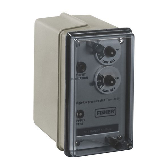
Figure 1. Type 4660 High-Low Pressure Pilot with Relay
11
Introduction
12
Scope of Manual
12
This instruction manual provides installation, operat-
12
ing, maintenance, and parts ordering information for
12
the Type 4660 high-low pressure pilot. Refer to sepa-
13
rate instruction manuals for information regarding the
control valve actuator.
13
Only qualified personnel should install, operate, and
13
maintain this pilot. If there are any questions concern-
ing these instructions, contact your Fisher sales office
14
or sales representative before proceeding.
Type 4660
Advertisement
Table of Contents

Related Manuals for Fisher 4660


Summary of Contents for Fisher 4660
-
Page 1: Table Of Contents
Principle of Operation ....Figure 1. Type 4660 High-Low Pressure Pilot with Relay Maintenance ...... -
Page 2: Description
3. Supply pressure at 35 psig (2.4 bar) Description ing mechanism in this pilot is a block-and-bleed relay assembly. The Type 4660 high-low pressure pilot (figure 1) acti- vates emergency shutdown systems for flowlines, pro- duction vessels, and compressors. The pilot can be Specifications... - Page 3 Type 4660 Table 2. Additional Specifications, Psig SET POINT P (MINIMUM ALLOWABLE DIFFERENCE BOURDON BETWEEN HIGH AND LOW SETTINGS) TUBE TUBE SET RANGE SET RANGE TRIP-TO-RESET ZONE TRIP TO RESET ZONE RATING Single High- High-Only/ Low Unit Low-Only Pair 3 to 97...
-
Page 4: Installation
(key 75, not shown) to the diaphragm casing of the actuator with the actuator cap screws and nuts. Standard pressure connections on the Type 4660 pilot Then attach the three-bossed side of the pilot case are 1/4-inch NPT female. Use 1/4 or 3/8-inch pipe or (key 2) to the three-holed side of the casing mounting tubing for process, output, and supply pressure piping. - Page 5 Type 4660 PROCESS SUPPLY NO. 2 SUPPLY PROCESS NO. 1 PROCESS OUTPUT OUTPUT OUTPUT OUTPUT 38A6084-B 38A6085-B PROCESS OUTPUT TO SUPPLY OUTPUT SUPPLY OUTPUT SUPPLY PROCESS NO. 1 PROCESS OUTPUT NO. 2 38A6086-B 38A6087-B ELECTRICAL PRESSURE SWITCH SUPPLY OUTPUT PROCESS...
-
Page 6: Supply Pressure
Due to the variability in nature of the problems these influences can have on pneumatic equipment, Fisher Output Pressure Controls has no technical basis to rec- ommend the level of filtration equipment... -
Page 7: Vent
Type 4660 Vent Provide some temporary means of process control before taking the pilot out of service, WARNING Shut off the process pressure line and the supply pressure line, and bleed all the supply pressure. If a flammable, toxic or reactive gas is to... -
Page 8: Setting The High Set Point
Type 4660 7. Continue with the appropriate procedures described To set the low set point pressure, perform the follow- below. Replace the cover and cover screws after all ing three steps: adjustments are completed. 1. Adjust the external pressure source to the desired low set point pressure. -
Page 9: Pilots With Optional Set Point Indication
Type 4660 Table 5. Alternate Set Point Adjustment PRESSURE PRESSURE BOURDON TUBE CHANGE CHANGE PER RATING PER DOT REVOLUTION Psig Psig Psig 17.2 34.5 1000 69.0 1500 103.4 12.4 2500 172.4 20.7 5000 344.8 41.4 7500 517.2 10.3 62.1 10,000 689.5... -
Page 10: Prestartup Checks
Type 4660 5. Repeat steps 1, 2, and 3 for the other module, if PERCENT OF BOURDON specified. TUBE RATING CONSTRUCTION Trip-to- Set Point Repeat- Reset ability Zone Prestartup Checks Single High-Low Unit 0 25 0.25 High-Only/Low-Only Pair Before using the pilot in an actual startup, verify that 1. -
Page 11: Performance
Type 4660 Performance SETPOINT PIVOT The performance characteristics shown in figure 6 il- PROCESS PRESSURE lustrate several important functional parameters. HIGH SET POINT PIVOT and S represent the low and high set points, re- LOW SETPOINT spectively. The set range is 3 to 97 percent of the ADJUSTMENT Bourdon tube rating. -
Page 12: Bourdon Tube/Flapper Assembly Replacement
Type 4660 Use lock-out procedures to be sure 6. Tighten the machine screws. that the above measures stay in effect 7. Refer to the alignment of the nozzle beam proce- while you are working on the equip- dure in the Operating Information section. -
Page 13: Pilots With Set Point Indication
67, 68, 69, 70, and 71) R4660X SPA12 Parts Ordering Set Point Indicator Whenever corresponding with the Fisher sales office ––– Set Point Indicator (Includes set or sales representative about this equipment, always point assembly and adjustment key) -
Page 14: Parts List
Type 4660 Description Part Number Description Part Number ––– Set Point Indicator (Includes set Machine Screw, stainless steel (4 req’d) 1J8415 X0012 point assembly and adjustment key) Self-Tapping Screw, stainless steel (5 req’d) 16A6959 X022 High Set Point Bourdon Tube Rating (cont’d) O-Ring, nitrile (3 req’d) - Page 15 Type 4660 APPLY SEALANT 48A3536-H/DOC Figure 8. Type 4660 Pilot Assembly...
- Page 16 18A3534 X602 Fisher, Fisher-Rosemount, and Managing The Process Better are marks owned by Fisher Controls International, Inc. or Fisher-Rosemount Systems Inc. All other marks are the property of their respective owners. Fisher Controls International, Inc. 1982, 1999; All Rights Reserved...
Need help?
Do you have a question about the 4660 and is the answer not in the manual?
Questions and answers