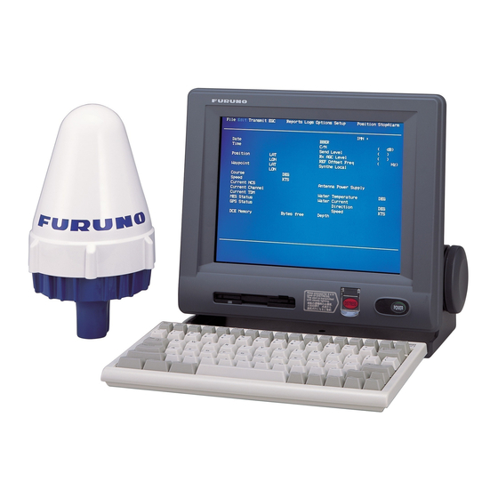
Furuno FELCOM 15 Installation Manual
Inmarsat-c mobile earth station
Hide thumbs
Also See for FELCOM 15:
- Service manual (228 pages) ,
- Operator's manual (228 pages) ,
- Specifications (2 pages)
Table of Contents
Advertisement
INMARSAT-C MOBILE EARTH STATION
TABLE OF CONTENTS
SAFETY INSTRUCTIONS .............................................................................................................i
EQUIPMENT LISTS......................................................................................................................ii
SYSTEM CONFIGURATION .......................................................................................................iv
1.
MOUNTING THE UNIT..........................................................................................................1
1.1
Antenna Unit.................................................................................................................1
1.2
Terminal Unit ................................................................................................................4
1.3
Distress Alert/Received Call Unit IC-305/Alarm Unit IC-306 ........................................6
1.4
Printer PP-510 (option)/EGC Printer PP-505 (option) ..................................................7
1.5
AC/DC Power Supply Unit PR-240 (option) .................................................................7
1.6
Junction Box IC-315 .....................................................................................................8
2.
WIRING .................................................................................................................................9
2.1
Antenna Cable Connector at the Terminal Unit..........................................................10
2.2
Distress Alert/Received Call Unit IC-305....................................................................13
2.3
Alarm Unit IC-306 .......................................................................................................14
2.4
Junction Box IC-315 ...................................................................................................15
3.
INITIAL SETTING................................................................................................................16
3.1
Setting the IMN (INMARSAT MOBILE NO.)...............................................................16
3.2
Setting for External Equipment...................................................................................17
4.
INSTALLATION OF GPS BOARD (OPTION).....................................................................18
5.
CHANGING POWER SUPPLY SPECIFICATIONS ............................................................21
PACKING LISTS....................................................................................................................... A-1
OUTLINE DRAWINGS.............................................................................................................. D-1
INTERCONNECTION DIAGRAM ............................................................................................. S-1
All brand and product names are trademarks, registered trademarks or service marks of their respective holders.
Installation Manual
www.furuno.com
FELCOM 15
Advertisement
Table of Contents

Subscribe to Our Youtube Channel
Related Manuals for Furuno FELCOM 15


Summary of Contents for Furuno FELCOM 15
-
Page 1: Table Of Contents
INMARSAT-C MOBILE EARTH STATION FELCOM 15 Installation Manual TABLE OF CONTENTS SAFETY INSTRUCTIONS ......................i EQUIPMENT LISTS........................ii SYSTEM CONFIGURATION .......................iv MOUNTING THE UNIT......................1 Antenna Unit.........................1 Terminal Unit ........................4 Distress Alert/Received Call Unit IC-305/Alarm Unit IC-306 ........6 Printer PP-510 (option)/EGC Printer PP-505 (option) ..........7 AC/DC Power Supply Unit PR-240 (option) ..............7... - Page 2 The paper used in this manual is elemental chlorine free. ・FURUNO Authorized Distributor/Dealer 9-52 Ashihara-cho, Nishinomiya, 662-8580, JAPAN Telephone : +81-(0)798-65-2111 : +81-(0)798-65-4200 A : DEC 2002 Printed in Japan All rights reserved. G2 : JAN . 17, 2012 Pub. No. IME-56350-G2...
-
Page 3: Safety Instructions
SAFETY INSTRUCTIONS CAUTION WARNING Do not open the equipment Confirm that the power supply voltage unless totally familiar with is compatible with the voltage rating electrical circuits and of the equipment. service manual. Connection to the wrong power supply Only qualified personnel ELECTRICAL can cause fire or equipment damage. -
Page 4: Equipment Lists
EQUIPMENT LISTS Standard Supply Name Type Code No. Remarks Antenna Unit IC-115 Terminal Unit IC-215 Distress Alert/ IC-305 Received Call Unit Alarm Unit IC-306 Junction Box IC-315 w/CP16-02501* CP16-02101 004-439-060 For 30 m antenna cable (w/o armor)* CP16-05001 001-101-960 For 30 m antenna cable (w/armor)* 1 set CP16-02111 004-439-070... - Page 5 Antenna Bracket CP16-03702 001-016-260 See page D-14. Antenna Mounting Pipe CP16-03703 001-014-510 *: See packing lists at the back of this manual. **: The SSAS modification kit is required for the SSAS. For installation of three IC-307s, additional SSAS alert unit is necessary.
-
Page 6: System Configuration
SYSTEM CONFIGURATION ANTENNA UNIT IC-115 DGPS EGC Printer** POWER SUPPLY 24 VDC PP-505 100-115/200-230 VAC TERMINAL UNIT 1φ, 50/60 Hz IC-215 Personal AC-DC Power Supply Printer Computer PR-240 (PC/AT compatible) POWER SUPPLY GPS Board OP16-47 12/24 VDC Shipboard LAN (Ethernet) Printer** PP-510 * For 12 VDC power supply,... -
Page 7: Mounting The Unit
1. MOUNTING THE UNIT NOTICE Do not apply paint, anti-corrosive sealant or contact spray to coating or plastic parts of the equipment. Those items contain organic solvents that can damage coating and plastic parts, especially plastic connectors. Antenna Unit Mounting Location •... - Page 8 1. MOUNTING THE UNIT • The allowable vibration level as specified by Inmarsat is as shown in the table below. Allowable vibration level Frequency Level 2 to 10 Hz 2.54 mm Peak Amplitude 10 to 100 Hz 9.8 m/s² Peak Acceleration •...
- Page 9 1. MOUNTING THE UNIT Earth wire (340 mm) Ground stud Mounting pipe Welding Antenna mast Mounting pipe and antenna mast For how to wire the antenna cable, see "Installation and Replacement of Antenna Unit", included with the antenna unit.
-
Page 10: Terminal Unit
1. MOUNTING THE UNIT Terminal Unit Select the following place to install the terminal unit. • The temperature and humidity should be moderate and stable. • For maintenance and checking purposes, leave sufficient space at the sides and rear of the unit and leave slack in cables. - Page 11 1. MOUNTING THE UNIT M4x20 230±0.5 4-R2.25 273±1 Dimensions for flush mounting Keyboard INM-C 15 1. Attach the function key label ( ) to the location shown below. Function key label (supplied) Prt Sc Scroll Pause Lock Lock Sys Rq Break &...
-
Page 12: Distress Alert/Received Call Unit Ic-305/Alarm Unit Ic-306
1. MOUNTING THE UNIT 1.3 Distress Alert/Received Call Unit IC-305/ Alarm Unit IC-306 ALARM ALARM Alarm unit IC-306 Distress alert/received call unit IC-305 Bulkhead mounting 1. Remove four screws from the unit to separate the bottom chassis from the top cover. 2. -
Page 13: Printer Pp-510 (Option)/Egc Printer Pp-505 (Option)
1. MOUNTING THE UNIT Printer PP-510 (option)/ EGC Printer PP-505 (option) PP-510 (option) Lay the printer on a table and fix it with printer fixtures 1 and 2. Attach labels appropriately; right side of printer for the compass safety distance label and front of printer for INMAR C label. -
Page 14: Junction Box Ic-315
1. MOUNTING THE UNIT Junction Box IC-315 The junction box IC-315 is connected to the terminal unit by using the cable assy 16S0344 (2 m, attached to the junction box). Install the junction box within 2 m from the terminal unit. 1. -
Page 15: Wiring
"SES (EGC)," in the SET UP EGC/SES menu, Distress alert/ referring to chapter 7 "SYSTEM SETTINGS" in the Alarm unit Received call operator's manual for DMC-5 (OME-5540). IC-306 unit Further, connect a jumper wire between TB5-#1 IC-305 and TB5-#3 on the DMC-5. Wiring of FELCOM 15... -
Page 16: Antenna Cable Connector At The Terminal Unit
2. WIRING Antenna Cable Connector at the Terminal Unit 5D-FB-CV-NP (30 m) Outer Sheath Inner Sheath Braided Shield Armor Remove the outer sheath, armor and inner sheath by the dimensions shown. Cover with heat-shrink tubing and heat. Washer Set the nut, washer, gasket, clamp onto cable as shown. - Page 17 2. WIRING 8D-FB-CV (50 m) Outer Sheath Dimensions in millimeters. Remove outer sheath and armor by the Armor Inner Sheath Shield dimensions shown left. Expose inner sheath and shield by the dimensions shown left. Cover with heat-shrink tubing and heat. Remove insulator and core by 10 mm.
- Page 18 2. WIRING 12D-SFA-CV (100 m) Dimensions in millimeters. Outer Sheath Armor Shield Inner Sheath Remove outer sheath and armor by the dimensions shown left. Expose inner sheath and shield by the dimensions shown left. Twist shield end. Slip on clamp nut, gasket and clamp as shown left. Clamp Gasket Washer...
-
Page 19: Distress Alert/Received Call Unit Ic-305
2. WIRING Distress Alert/Received Call Unit IC-305 Use the installation material CP16-02201 to connect the distress alert IC-305. The optional CO-SPEVV-SB-C 0.2x5P cable or JIS cable (Japan Industrial Standards) TTYCS-4 or equivalent are available to connect with the junction box IC-305. -
Page 20: Alarm Unit Ic-306
2. WIRING Alarm Unit IC-306 Maximum three alarm units can be connected to the junction box IC-315 in parallel. To distinguish the incoming indictors, set jumper wires for the second alarm unit as below. For connection, refer to the “2.2 Distress Alert/Received Call Unit IC-305.”... -
Page 21: Junction Box Ic-315
2. WIRING Junction Box IC-315 Use the junction box IC-315 to connect the distress alert/received call unit IC-305 and other unit (max. four units) to the terminal unit. Unfasten four screws to remove the box cover to connect cables. For connection, use the optional 5 pair cable CO-SPEVV-SB-C 0.2x5P, JIS cable (Japan Industrial Standards) TTYCS-4 or equivalent. -
Page 22: Initial Setting
3. INITIAL SETTINGS Setting the IMN (INMARSAT MOBILE NO.) After the wiring, set your IMN (Inmarsat Mobile No.) as below. 1. Turn the power on. 2. Press the function key [F8] to show the Setup menu. File Edit Transmit Reports Logs Options Setup... -
Page 23: Setting For External Equipment
3. INITIAL SETTINGS Setting for External Equipment The FELCOM 15 system had been set to accommodate to distress alert/received call unit IC-305, up to three alarm units IC-306 and distress message controller DMC-5 at factory. If less than three units are connected, change the setting to OFF as below. -
Page 24: Installation Of Gps Board (Option)
4. INSTALLATION OF GPS BOARD (OPTION) This chapter provides the procedure for the installation of the GPS board (in the terminal unit), which provides GPS position information. Name: GPS board Type: OP16-47 Code No.: 000-017-110 Name Type Code No. Remarks GPS board 16P0246 004-656-550... - Page 25 4. INSTALLATION OF GPS BOARD (OPTION) 2. Unfasten four pan head screws (M3x8) to remove the RF cover (S). 3. Fasten three pan head screws (M3x8, supplied with the kit) to attach the GPS board to the RF cover. 4. Attach the 7P connector from the RF cover to the JI on the GPS board. Cable Pan head screw M3x8, 3 pcs.
- Page 26 4. INSTALLATION OF GPS BOARD (OPTION) 7. Reassemble the terminal unit as below. ○ a) Fasten six spacers a by hand tentatively. ○ b) Fasten eight pan head screws b tightly. ○ c) Fasten six spacers a by box driver tightly. d) Fasten other screws and washers to complete.
-
Page 27: Changing Power Supply Specifications
5. CHANGING POWER SUPPLY SPECIFICATIONS The AC-DC power supply PR-240 is shipped ready for connection to a 200-230 VAC ship’s mains. If the ship’s mains is 100 VAC-115 VAC, change the tap connection and terminal board connection as below. Attach a label supplied as accessories to the front panel according to the ship’s mains. - Page 36 Y.NISHIYAMA 13/Jan/2012...
- Page 41 July 14'03...
- Page 43 Dec. 20, '02...
- Page 44 Mar.03'05...
- Page 45 D-10...
- Page 46 D-11...
- Page 47 D-12...
- Page 48 D-13 Y.NISHIYAMA 13/Jan/2012...
- Page 49 D-14 Y.NISHIYAMA 13/Jan/2012...
- Page 50 D-15...
-
Page 51: Interconnection Diagram
*5. TB BOARD (16P0116) REQUIRED. SCALE MASS NAME INMARSAT-C MES CO-0.2x2P: CO-SPEVV-SB-C 0.2x2P,φ10.5 *6. CHANGE SETTING OF JUMPER IN IC-307 TO TERMINATE. CO-0.2x5P: CO-SPEVV-SB-C 0.2x5P,φ13.5 DWG No. INTERCONNECTION DIAGRAM *7. DO NOT SHORTEN ANTENNA CABLE. C5635-C01- S FURUNO ELECTRIC CO., LTD.
Need help?
Do you have a question about the FELCOM 15 and is the answer not in the manual?
Questions and answers