Advertisement
Quick Links
REPLACEMENT INSTRUCTIONS
CAPACITOR INSTALLATION KIT OP05-143
AT-1575 ANTENNA COUPLER PCB
These instructions cover how to replace the PCB of AT-1575 antenna coupler for the SSB Radio
Telephone FS-1575.
Note: Check the PCB version before replacement. The replacement board should be ordered
before proceeding with these instructions.
The new board 05P0883-22 (Code: 000-176-005-12) is not included with this kit.
Where the new board is already installed in the AT-1575, board replacement is not required.
Replacement kit
The contents of the kit are listed in the following table.
Capacitor Installation Kit OP05-143 (Code: 001-476-140)
Fixing Plate
Clamp
Washer Head Screw
Wire Assembly (Type AF)
How to remove the old PCB
1.
Unfasten the pan head screws (M4x14, 8 pcs.), then remove the cover.
Name
05-062-0253
CKN-05
M4x6
AF1160GG-L100
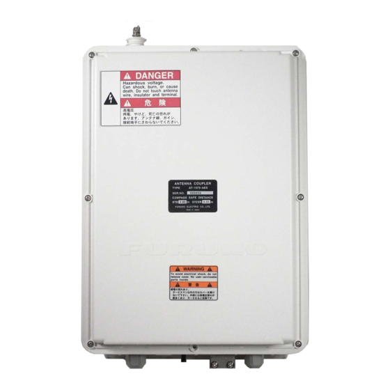
Fig.1: Antenna Coupler AT-1575
Type
Pan head screws
www.furuno.com
Code
Qty.
100-199-261-10
1
000-193-375-10
1
000-163-176-10
2
001-482-240
1
Advertisement

Related Manuals for Furuno AT-1575


Summary of Contents for Furuno AT-1575
- Page 1 REPLACEMENT INSTRUCTIONS CAPACITOR INSTALLATION KIT OP05-143 AT-1575 ANTENNA COUPLER PCB These instructions cover how to replace the PCB of AT-1575 antenna coupler for the SSB Radio Telephone FS-1575. Note: Check the PCB version before replacement. The replacement board should be ordered before proceeding with these instructions.
- Page 2 Clamp3 Protection Coaxial Cable plate Fig.2: Inside of the AT-1575 (Before replacement of the board) Check the version of the Board. Disconnect the wires from TB5. Unfasten the screw on TB4 (M4x6), then disconnect the shield cable. Unfasten the washer head screws (M3x12), then remove clamp4.
- Page 3 Clamp3 Hex-nut 13. Use a cutter to remove the double-sided tape on Clamp 3, then remove the clamp. 14. Unfasten the hex-nut with a spanner. 15. Fix the new clamp to the location indicated in the figure below. Use the double-sided tape attached to the clamp to secure the clamp in place.
- Page 4 Clamp3 Coaxial Cable plate Fig.3: Inside of the AT-1575 (After replacement of the board) Connect the cables to J1 and J2. Referring to the above figure, secure the cables with their cable clamps. Connect the transmission cable to TB3 with the screw (M4x6).
- Page 5 Fasten wire assembly (Type AF, supplied) to the fixing plate with the supplied washer head screw. Recommended fastening torque is 1.2Nm Wire assembly (Type AF) Washer head screw Check the gasket is engaged to the posts on the casing then fasten the cover with the pan head screws (M4x14, 8 pcs.).
- Page 8 ア レ ス タ 板に、 TB4 の付属ネジ (M4×6) で、 信号ケーブルのシール ド にあ る圧着端子を固定 し ま す。 TB5 の接続は、 下図の通 り です。 支給のナベセムスネジ (M4×6) を使 っ て、 基板取外 し 手順 19 で取 り 付けた線加工 AF 型 (支給分) を基板取外 し 手順 17 で取 り 付けたア レ ス タ 板に固定 し ます (締め付け ト ル ク : 1.2N ・ m) 。 下図を参照...
- Page 9 カ プ ラ ー基板取付け手順 ア ン テナ カ プ ラ ー AT-1575 内部 (基板交換後) ク ラ ン プ 1 で、 線加工 AF 型を固定 し ます。 ク ラ ン プ 2 と 3 に、 線加工 AF 型 と 受信用 ミ ニ ピ ン ケーブルを挿入 し ます。...
- Page 10 カ ッ タ ーを使 っ て ク ラ ン プ 3 の両面テープ部を剥が し 、 ク ラ ン プ 3 を取 り 外 し ます。 スパナ を使 っ て、 六角ナ ッ ト (05S9337) を回 し て取 り 外 し ます。 下記の手順 17 にあ る図の通 り 、 ク ラ ン プに付いている両面テープ を使 っ て、 支給の...
- Page 11 注) 取り外したネジ、押え板、保護板とケーブルは再度使用しますので、廃棄しないでください。 ア ン テナ カ プ ラ ー AT-1575 内部 (基板交換前) 基板のバージ ョ ン を確認 し ます。 端子台 (TB5) か ら、 信号ケーブルを外 し ます。 端子台 (TB4) の付属ネジ (M4×6) を緩め、 信号ケーブルのシール ド を外 し ます。 端子台 (TB1) の押え板にあ る ナベセムスネジ (M3×12) を 2 カ所緩め、 同軸ケーブルの...
- Page 12 カ プ ラ ー基板交換要領書 本要領書は、 SSB 送受信機 FS-1575 のア ン テナ カ プ ラ ー、 AT-1575 に取 り 付け ら れてい る カ プ ラ ー基板 を交換する手順を記載 し ています。 本キ ッ ト と カ プ ラ ー基板 (別途手配) を使 っ て、 本書の記載手順...
Need help?
Do you have a question about the AT-1575 and is the answer not in the manual?
Questions and answers