
Related Manuals for Bender RCMA423-DM


Summary of Contents for Bender RCMA423-DM
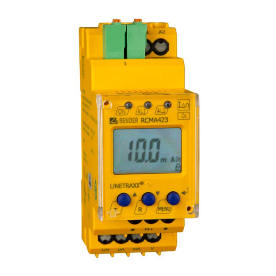
- Page 1 Manual RCMA423-DM Residual current monitor with one analogue output signal for monitoring AC-, DC- and pulsed DC currents in TN- and TT systems Software version: D330 V1.0x RCMA423-DM_D00064_03_M_XXEN/06.2017...
- Page 2 Bender GmbH & Co. KG P.O. Box 1161 • 35301 Gruenberg • Germany Londorfer Strasse 65 • 35305 Gruenberg • Germany Tel.: +49 6401 807-0 • Fax: +49 6401 807-259 E-Mail: info@bender.de • www.bender.de © Bender GmbH & Co. KG All rights reserved.
-
Page 3: Table Of Contents
Table of Contents 1. Important information ..................7 How to use this manual ................. 7 Technical support: service and support ........... 8 1.2.1 First level support ..................... 8 1.2.2 Repair service ..................... 8 1.2.3 Field service ......................9 Training courses ..................... 10 Delivery conditions .................. - Page 4 Table of Contents 3.2.9 Password protection (on, OFF) ..............17 3.2.10 Factory setting FAC ..................17 3.2.11 Erasable history memory ................17 3.2.12 Fault memory ....................18 3.2.13 Interface ......................18 4. Installation and connection ................. 19 Mounting ......................20 Wiring ........................
- Page 5 6.3.1 RCMA423… ..................... 44 6.3.2 External measuring current transformers ........... 44 6.3.3 Connecting wires measuring current transformer ......44 6.3.4 Accessories RCMA423-DM ................. 44 6.3.5 Measuring current transformer accessories ........45 Current and voltage curves of the analogue interface ....45 Error codes .......................
- Page 6 Table of Contents RCMA423-DM_D00064_03_M_XXEN/06.2017...
-
Page 7: Important Information
1. Important information 1.1 How to use this manual This manual is intended for qualified personnel working in electrical engineering and electronics! Always keep this manual within easy reach for future reference. To make it easier for you to understand and revisit certain sections in this man- ual, we have used symbols to identify important instructions and information. -
Page 8: Technical Support: Service And Support
Important information This manual has been compiled with great care. It might nevertheless contain errors and mistakes. Bender cannot accept any liability for injury to persons or damage to property resulting from errors or mistakes in this manual. 1.2 Technical support: service and support For commissioning and troubleshooting Bender offers you: 1.2.1... -
Page 9: Field Service
Important information Bender GmbH, Repair-Service, Londorfer Str. 65, 35305 Gruenberg 1.2.3 Field service On-site service for all Bender products Commissioning, configuring, maintenance, troubleshooting of Bender products Analysis of the electrical installation in the building (power quality test, ... -
Page 10: Training Courses
ZVEI (Zentralverband Elektrotechnik- und Elektronikindustrie e. V.) (German Electrical and Electron- ic Manufacturer's Association) also applies. Sale and delivery conditions can be obtained from Bender in printed or elec- tronic format. 1.5 Inspection, transport and storage Inspect the dispatch and equipment packaging for damage, and compare the contents of the package with the delivery documents. -
Page 11: Warranty And Liability
Important information 1.6 Warranty and liability Warranty and liability claims in the event of injury to persons or damage to property are excluded if they can be attributed to one or more of the follow- ing causes: Improper use of the device. ... -
Page 12: Disposal
13 August 2005 must be taken back by the manufacturer and disposed of properly. For more information on the disposal of Bender devices, refer to our homepage at www.bender-de.com -> Service & support. -
Page 13: Safety Instructions
EN 50110 can be used as a guide. 2.3 Intended use The AC/DC sensitive residual current monitoring device RCMA423-DM is used for monitoring of earthed systems (TN and TT systems), in which DC or AC fault currents can occur. Part of these systems are particularly loads contai-... -
Page 14: Information Regarding Factory Setting
Only use the output you have selected via the software: – DC 0…400 μA Current output for Bender measuring instruments of the 96.. series. – DC 0/4…20 mA Standardised current output with selectable current ranges. -
Page 15: Function
3. Function 3.1 Device features AC/DC sensitive residual current monitor type B acc. to IEC 62020 and IEC/TR 60755 Two separately adjustable response value ranges (prewarning, alarm) Adjustable switching hysteresis r.m.s. value measurement Start-up delay ... -
Page 16: Connection Monitoring
Function The device function can be tested using the test button T. Parameters are as- signed to the device via the LCD and the control buttons on the front panel; this function can be password-protected. 3.2.1 Connection monitoring The connections to the measuring current transformer are constantly monito- red. -
Page 17: Malfunction
Function 3.2.5 Malfunction In the event of an internal malfunction, all three LEDs will flash. The display shows an error code (E01…E32). In such a case please contact the Bender Ser- vice. 3.2.6 Specifying the number of reload cycles If an error occurs in the monitored system and the system has to be switched off by the alarm relay, with the fault memory M deactivated the alarm relay would switch synchronously to the error status. -
Page 18: Fault Memory
(full-scale deflection of the connected measuring device), only the output selected via the software may be terminated: – DC 0…400 μA Current output for Bender measuring instruments of series 96… – DC 0…20 mA/4…20 mA Standardised current output with two selectable ranges –... -
Page 19: Installation And Connection
4. Installation and connection Ensure that there is no voltage in the installation area and follow the rules for working on electrical equipment! DANGER Dimension diagram, drawing for screw fixing, push-wire terminal connection 36 mm RCMA423-DM_D00064_03_M_XXEN/06.2017... -
Page 20: Mounting
Use a tool to position the rear mounting clips so that they project bey- ond the enclosure (a second mounting clip is required, see ordering information). Then fix the device using two M4 screws. 4.2 Wiring Connect the device according to the wiring diagram. Fig. 4.1: Wiring diagram RCMA423-DM RCMA423-DM_D00064_03_M_XXEN/06.2017... - Page 21 Installation and connection Legend for wiring diagram RCMA423-DM Terminal Connections A1, A2 Connection to supply voltage U k, l Connection for measuring current transformer T/R Connection to combined test and reset button M+ (Common) positive pole of the analogue interface μA Current output 0…400 μA...
- Page 22 Installation and connection RCMA423-DM_D00064_03_M_XXEN/06.2017...
-
Page 23: Operation And Setup
5. Operation and setup 5.1 Display elements The meaning of the display elements in use is listed in the table below. Elemen Display elements Function Reload function with memory = off (L = I.) Response value I in mA Δn2 (alarm 2, main alarm) Response value I in % of I... -
Page 24: Function Of The Operating Elements
Operation and setup 5.2 Function of the operating elements User interface Element Function is continuously lit: Power On LED, flashes: system fault or malfunction green of connection monitoring LED alarm 1 is lit (yellow): Response value 1 has been reached AL1, Δ... -
Page 25: Menu Structure
Operation and setup 5.3 Menu structure All adjustable parameters are listed in the columns Menu and Adjustable pa- rameter. A display-like representation is used to illustrate the parameters in the column Menu. Menu Activati Menu Submenu Adjustable parameter item (alarm 2) >... -
Page 26: Display In Standard Mode
History memory for the first alarm value, erasable Tab. 5.1: Menu structure RCMA423-DM 5.4 Display in standard mode The currently measured residual current is indicated in the factory setting. By pressing the arrow-up and arrow-down button, the current response values I1 (prewarning) and I2 (alarm) are displayed. -
Page 27: Display In Menu Mode
Operation and setup 5.5 Display in menu mode 5.5.1 Querying and setting parameters: Overview Menu Adjustable parameter item Querying and setting response values: – Residual current I (AL2) Δn2 – Residual current I (AL1) Δn1 – Hysteresis of the response values: % Hys Configuring fault memory: –... - Page 28 Operation and setup Menu structure RCMA423-DM_D00064_03_M_XXEN/06.2017...
-
Page 29: Parameter Settings
Operation and setup 5.5.2 Parameter settings By way of example, the modification of the alarm response value I1 (I ) is de- Δn1 scribed. It is presumed that the option overcurrent (HI) has been selected in the SEt/I12 menu (factory setting). Proceed as follows: 1. -
Page 30: Response Value Setting For Overcurrent
Operation and setup 5.5.4 Response value setting for overcurrent: - Response value I2 (overcurrent) - Response value I1 (overcurrent) - Hysteresis (Hys) of the response values I1, I2 Increasing the response value I2 (Example: overcurrent) Increasing the response value I1 (prewarning overcurrent) Setting the hysteresis of the response value RCMA423-DM_D00064_03_M_XXEN/06.2017... -
Page 31: Setting The Fault Memory To "Con" Mode
Operation and setup 5.5.5 Setting the fault memory to "con" mode 5.5.6 Setting the number of reload cycles 5.5.7 Selecting output current range of the analogue interface 0.0.4 mA represents 0…400 μA 0.20 mA represents 0…20 mA; 4.20 mA represents 4…20 mA RCMA423-DM_D00064_03_M_XXEN/06.2017... -
Page 32: Selecting The Output Voltage Of The Analogue Interface
Operation and setup 5.5.8 Selecting the output voltage of the analogue interface 0.10 V represents 0…10 V RCMA423-DM_D00064_03_M_XXEN/06.2017... -
Page 33: Setting The 100 % Reference For The Analogue Interface
Operation and setup 5.5.9 Setting the 100 % reference for the analogue interface Set here whether the 100% value of the output signal is to be coupled to the response value I2 (I ) (AL) or to a freely configurable value. A configurable Δn2 value range from 30mA to 3A is available. -
Page 34: Setting Delay Times
Operation and setup 5.5.10 Setting delay times The following delays can be set: Start-up delay t (0…10 s) when starting the device Setting the start-up delay 5.5.11 Changing from overcurrent operation to window operation Use this menu item to set whether the response values of the device apply to overcurrent (HI) or undercurrent operation (Lo). -
Page 35: Factory Setting And Password Protection
Operation and setup 5.5.12 Factory setting and password protection This menu can be used to activate the password protection, to modify the password or to deactivate the password protection. It is also where the device can be reset to the factory settings. a) Activating the password protection b) Changing the password RCMA423-DM_D00064_03_M_XXEN/06.2017... -
Page 36: Restoring The Factory Settings
Operation and setup c) Deactivating the password protection 5.5.13 Restoring the factory settings RCMA423-DM_D00064_03_M_XXEN/06.2017... -
Page 37: Querying Device Information
Operation and setup 5.5.14 Querying device information This function is used to query the software version (1.xx). After activating this function, data will be displayed as a scrolling text. Once one pass is completed you can select individual data sections using the arrow-up/arrow-down but- tons. -
Page 38: Factory Setting
Operation and setup 5.7 Factory setting Response value I 30 mA (I2) Δn2 Response value I 50 % (I1) Δn1 Hysteresis 15 % Fault memory M activated (on) RL (Reload function) 100% reference for the analogue interface Response value I2 Start-up delay t = 0.5 s Password... -
Page 39: Technical Data
6. Technical data 6.1 Tabular data ( )* = factory setting Insulation coordination acc. to IEC 60664-1/IEC 60664-3 RCMA423-DM-1: Rated insulation voltage........................100 V Overvoltage category/pollution degree .................... III/3 Rated impulse withstand voltage....................2.5 kV RCMA423-DM-2: Rated insulation voltage......................... 250 V Overvoltage category/pollution degree .................... - Page 40 Technical data Relative uncertainty at f ≤ 2 Hz or ≥ 16 Hz ....................0…-35 % Relative uncertainty at f > 2 Hz…<16 Hz..................-35 %…+100 % Operating uncertainty............................. 0…35 % Response values Rated residual operating current I (prewarning, AL1) ..........50…100 % x I (50 %)* Δn1 Δn2...
- Page 41 Technical data Inputs/outputs Cable length for external test/reset button ....................0…10 m Voltage output Open circuit voltage (terminals open) ......................≤ DC 20 V Voltage output............................DC 0…10 V Load..................................≥ 1 kΩ Resolution ................................50 mV Tripping time 1 x I .............................>...
- Page 42 Technical data Connection For UL applications: Copper lines ......................at least 60/70 °C Connection type......................screw-type terminals Connection properties: Rigid/flexible....................0.2…4/0.2…2.5 mm (AWG 24…12) Multi-conductor connection (2 conductors with the same cross section): Rigid/flexible........................0.2…1.5/0.2…1.5 mm Stripping length ............................. 8…9 mm Tightening torque .............................
-
Page 43: Standards, Approvals And Certifications
Technical data Residual operating current ranges of the different measuring cur- rent transformer Residual operating Typ. current ranges 30 mA…500 mA W20AB W35AB(P) 30 mA…3 A W60AB(P) W120AB 300 mA…3 A W210AB 6.2 Standards, approvals and certifications The device was designed according to the following standards: - IEC 62020 - IEC/TR 60755 RCMA423-DM_D00064_03_M_XXEN/06.2017... -
Page 44: Ordering Information
Connecting wires measuring current transformer Type Length (m) Art. no. WX-100 B 9808 0503 WX-250 B 9808 0504 WX-500 B 9808 0505 WX-1000 B 9808 0506 6.3.4 Accessories RCMA423-DM Mounting clip for screw fixing (1 piece per device) .................. B 9806 0008 RCMA423-DM_D00064_03_M_XXEN/06.2017... -
Page 45: Measuring Current Transformer Accessories
Technical data 6.3.5 Measuring current transformer accessories Snap-on mounting for DIN rail: W20AB /W35AB(P) ................B 9808 0501 Snap-on mounting for DIN rail: W60AB(P) ....................B 9808 0502 6.4 Current and voltage curves of the analogue interface Current output 0/4…20 mA Current output 0…400 μA RCMA423-DM_D00064_03_M_XXEN/06.2017... -
Page 46: Error Codes
Technical data Voltage output 0…10 V 6.5 Error codes If, contrary to expectations, a device error should occur, error codes will ap- pear on the display. Some of these are described below: Error code Meaning Fault CT monitoring Action: E.01 Check transformer connection for short-circuit or inter- ruption. - Page 47 Error code Meaning Error codes > 02 Action: Perform a reset. Restore the factory setting of the device. E… The error code will be erased automatically once the error has been eliminated. Should the error persist, contact Bender Service RCMA423-DM_D00064_03_M_XXEN/06.2017...
- Page 48 Technical data RCMA423-DM_D00064_03_M_XXEN/06.2017...
-
Page 49: Index
INDEX Adjustable parameters, list 25 Malfunction 17 Automatic self test 16 Manual self test 16 Measuring current transformer, residual operating current ranges 43 Device features 15 Menu Display elements 23 - AL (response values) 25 Display in standard mode 26 - HiS (history memory for the first alarm value) 26 - InF (hard and software version) 26... - Page 50 analogue interface 31 Wiring diagram 20 - Setting delay times 34 Work activities on electrical installations 13 Password protection 17 workshops 10 Querying and setting parameters, overview Reset button 24 Residual current monitoring in window mo- de 17 Response value setting - Hysteresis 30 - Overcurrent (>...
- Page 52 Bender GmbH & Co. KG Londorfer Str. 65 • 35305 Gruenberg • Germany Postfach 1161 • 35301 Gruenberg • Germany Tel.: +49 6401 807-0 Fax: +49 6401 807-259 Email: info@bender.de www.bender.de Group Photos: Bender archives and bendersystembau archives.
Need help?
Do you have a question about the RCMA423-DM and is the answer not in the manual?
Questions and answers