Table of Contents
Advertisement
Quick Links
Advertisement
Table of Contents

Subscribe to Our Youtube Channel
Related Manuals for NXP Semiconductors JN517x-DK005


Summary of Contents for NXP Semiconductors JN517x-DK005
- Page 1 JN517x-DK005 Development Kit User Guide JN-UG-3121 Revision 1.1 8 February 2017...
- Page 2 JN517x-DK005 Development Kit User Guide © NXP Semiconductors 2017 JN-UG-3121 v1.1...
-
Page 3: Table Of Contents
JN517x-DK005 Development Kit User Guide Contents Preface Organisation Conventions Acronyms and Abbreviations Related Documents Support Resources Optional Components Trademarks 1. Introduction to the Development Kit 1.1 Kit Contents 1.2 Wireless Network Fundamentals 1.2.1 Radio Frequency 1.2.2 Network Identification 1.2.3 Node Types 1.2.4 Network Formation and Topology... - Page 4 A.7 NFC Controller B. Installing a Packet Sniffer C. Firmware Re-programming C.1 Re-programming JN5179 Modules C.2 Re-programming JN5179 USB Dongles D. Installing the FTDI Device Driver for USB Connections E. Regulatory Information E.1 FCC Regulatory Statements © NXP Semiconductors 2017 JN-UG-3121 v1.1...
-
Page 5: Preface
JN517x-DK005 Development Kit User Guide Preface This manual provides an introduction to the NXP JN517x-DK005 Development Kit, based around the JN517x family of wireless microcontrollers. The manual also describes how to run the pre-loaded ZigBee Smart Home Demonstration using components from the kit. In addition, information is provided on the wireless network protocols supported by the development kit and the NXP resources available to develop custom JN517x applications using these protocols. -
Page 6: Conventions
FTDI Future Technology Devices International GPIO General Purpose Input/Output Home Automation IEEE Institute of Electrical and Electronics Engineers Internet of Things Internet Protocol JTAG Joint Test Action Group Local Area Network Light Emitting Diode © NXP Semiconductors 2017 JN-UG-3121 v1.1... -
Page 7: Related Documents
JN517x-DK005 Development Kit User Guide LPRF Lower Power Radio Frequency Near Field Communication Power Supply Unit Pulse Width Modulation Radio Frequency RTOS Real Time Operating System Single Board Computer Software Developer’s Kit SubMiniature version A SSID Service Set Identifier UART... -
Page 8: Optional Components
About this Manual Optional Components The following additional/optional hardware components are available for use with the JN517x-DK005 Development Kit: Part Number Name JN517x-XK030 Generic Node Expansion Kit JN517x-XK040 Lighting/Sensor Node Expansion Kit OM15021 JN5179 USB Dongle These products can be individually ordered via the NXP web site (www.nxp.com). -
Page 9: Introduction To The Development Kit
User Guide 1. Introduction to the Development Kit Welcome to the JN517x-DK005 Development Kit, which is based around the NXP JN517x family of wireless microcontrollers. A ZigBee Smart Home Demonstration is pre-loaded into certain kit components, allowing a small wireless network with IP connectivity to be quickly assembled and used. -
Page 10: Kit Contents
Introduction to the Development Kit 1.1 Kit Contents The JN517x-DK005 Development Kit contains the hardware components required to assemble a wireless network which may be connected to an IP-based network (such as the Internet). The principal network components included in the kit are: ... - Page 11 JN517x-DK005 Development Kit User Guide The full contents of the kit are listed below (numbers refer to Figure 1 above). (Note a) 1. Raspberry Pi 2 single-board computer (Model B) and microSD card 2. Wi-Pi Raspberry Pi 802.11n wireless adaptor (for Wi-Fi connectivity) (Note b) 3.
-
Page 12: Wireless Network Fundamentals
1.2 Wireless Network Fundamentals This section covers the basic concepts that are relevant to the wireless network protocols supported by the JN517x-DK005 Development Kit, notably IEEE 802.15.4 and ZigBee PRO (which is itself built on IEEE 802.15.4) used in the ZigBee 3.0 standard. -
Page 13: Network Identification
JN517x-DK005 Development Kit User Guide 1.2.2 Network Identification A wireless network must have a unique identifier which allows it to be distinguished from other networks in the same operating neighbourhood. IEEE 802.15.4-based protocols use a 16-bit value called the PAN ID. This identifier can be pre-defined in the... -
Page 14: Network Formation And Topology
1.2.4.1 Star Networks A Star network contains only one routing node, which is the Co-ordinator. Thus, all messages between the network nodes are routed via the central Co-ordinator. Co-ordinator Figure 3: Star Network © NXP Semiconductors 2017 JN-UG-3121 v1.1... -
Page 15: Tree Networks
JN517x-DK005 Development Kit User Guide 1.2.4.2 Tree Networks A Tree network may contain the full range of node types - Co-ordinator, Routers and End Devices - with the Co-ordinator at the top of the (inverted) tree. Any node can only communicate directly with its parent and children (if any). -
Page 16: Wireless Network Protocol Stack
Flash memory of the node. In order to use the ZigBee Smart Home Demonstration that is pre-loaded in the JN517x-DK005 Development Kit boards, no knowledge of the protocol software is required. However, you should familiarise yourself with the software for your chosen protocol before starting your own application development - refer to Section 3.3... -
Page 17: Internet Of Things (Iot)
JN517x-DK005 Development Kit User Guide 1.3 Internet of Things (IoT) The ‘Internet of Things’ (IoT) refers to the concept of electrical devices being connected via the Internet, irrespective of their basic functionality. This allows the devices to be remotely controlled and monitored from other devices on the Internet - for example, from a PC, tablet or smart phone. -
Page 18: Ip Connectivity Of The Kit
Figure 8: Basic Architecture of an IoT Gateway 1.3.2 IP Connectivity of the Kit In the JN517x-DK005 Development Kit, an IoT Gateway can be formed from the Raspberry Pi board together with a JN5179 USB Dongle: The Raspberry Pi provides the IP Host, interfacing to the IP domain ... -
Page 19: Network Commissioning
NFC commissioning is becoming an important technique in establishing this security and is supported by the JN517x-DK005 Development Kit. NFC commissioning is outlined in Section 1.4.1. -
Page 20: Nfc Commissioning Process
The joining node now has the network key which allows it to subsequently participate in secure network-level communications. Therefore, the network credentials are never sent over the air, providing a safer method of commissioning. The JN517x-DK005 Development Kit is equipped with the necessary components for NFC commissioning: The supplied Carrier Boards (see Appendix A.1) feature ‘NFC connected tags’. -
Page 21: Addressing, Binding And Grouping
JN517x-DK005 Development Kit User Guide 1.4.2 Addressing, Binding and Grouping The available methods for establishing a functional link between a controlling node or source node and a target node are as follows: Direct Addressing: The source node can simply send commands to the address of the target node. -
Page 22: Zigbee Smart Home Demonstration
More detailed information and instructions on how to run the demonstration are provided in Chapter Note 1: A Quick Start procedure for running this demonstration is also provided on the JN517x-DK005 Getting Started sheet (JN-UG-3120), which is supplied in the kit box. Note 2: The demonstration applications are based on the ZigBee 3.0 devices detailed in the Application Notes... -
Page 23: Zigbee Smart Home Demonstration
User Guide 2. ZigBee Smart Home Demonstration The chapter describes how to use the contents of the JN517x-DK005 Development Kit to set up and run the pre-loaded ZigBee Smart Home Demonstration. The demonstration is concerned with the control of a light in a ‘Smart Home’ and has the following features: ... - Page 24 JN5179 USB Dongle, acting as the ZigBee Co-ordinator and providing the connection to the WPAN NFC Controller Board, providing NFC commissioning The Dimmable Light and Dimmer Switch nodes both act as ZigBee Routers. © NXP Semiconductors 2017 JN-UG-3121 v1.1...
-
Page 25: Setting Up The Iot Gateway
JN517x-DK005 Development Kit User Guide 2.2 Setting Up the IoT Gateway This section describes how to set up the IoT Gateway for the ZigBee Smart Home Demonstration. As detailed in Section 2.1, the IoT Gateway comprises: Raspberry Pi 2 board ... - Page 26 After around 20 seconds, an audible beep will be sounded by the Raspberry Pi. The IoT Gateway is then ready. When in this state, the green LED on the NFC Controller board flashes. The Wi-Pi adaptor will have created a Wi-Fi network (initially consisting of only itself). © NXP Semiconductors 2017 JN-UG-3121 v1.1...
- Page 27 JN517x-DK005 Development Kit User Guide Step 8 Direct a web browser on the PC to the IoT Gateway a) Connect the PC to the ZigBee network via the IoT Gateway by specifying the SSID (name) of the network, which is Iot_GW_NXP.
-
Page 28: Commissioning Nodes
‘NFC tap’ and is shown in Figure 11. An audible signal is sounded if the NFC communication between the two devices was successful, after which the node will join the ZigBee network. Figure 11: NFC Tap © NXP Semiconductors 2017 JN-UG-3121 v1.1... - Page 29 JN517x-DK005 Development Kit User Guide Caution: In performing an NFC tap, do not allow the components to get close enough to short the pins on the bottom of the Carrier Board to the metal screening shield of the NFC board.
- Page 30 In the web browser on the PC, go to the “Mobile Site” tab by clicking the Mobile Site button (right-most button across the top) and check that the Dimmable Light appears on the page - the light will be identified by its IEEE/MAC address. © NXP Semiconductors 2017 JN-UG-3121 v1.1...
- Page 31 JN517x-DK005 Development Kit User Guide Step 8 Bind the Dimmer Switch to the Dimmable Light It is now possible to bind the Dimmer Switch to the Dimmable Light (so that they will operate together). To bind the Dimmer Switch to the Dimmable Light: a) Press and release the Commissioning button (GPIO4) on the Carrier Board of the Dimmable Light node.
-
Page 32: Controlling The Light
The four buttons SW1-SW4 on the Generic Expansion Board are used to control the lights, as follows: Button Action Switch on lights Switch off lights Increase brightness of lights Decrease brightness of lights Table 2: Button Usage on Dimmer Switch © NXP Semiconductors 2017 JN-UG-3121 v1.1... -
Page 33: Controlling The Dimmable Light From The Pc
JN517x-DK005 Development Kit User Guide 2.4.2 Controlling the Dimmable Light from the PC The Dimmable Light within the ZigBee network can be controlled from the IoT Gateway interface on a web browser on a PC (refer to the step “Direct a web browser on the PC to the IoT Gateway”... - Page 34 Enter a brightness level as a decimal fraction in the range 0 to 1.0 into the numerical field. Click on and move the widget on the greyscale background to the desired brightness level. © NXP Semiconductors 2017 JN-UG-3121 v1.1...
-
Page 35: Where Next
Once you have set up and run the pre-loaded ZigBee Smart Home Demonstration, you may wish to start developing your own wireless network applications to run on the components of the JN517x-DK005 Development Kit. This chapter helps you to get started in this application development, as follows: ... -
Page 36: Software Developer's Kit (Sdk)
SDK installer. These plug-ins include: JN517x SDK for relevant networking protocol JN517x Flash programmer Serial terminal view For installation and operational guidance, first refer to the JN517x LPCXpresso Installation and User Guide (JN-UG-3109). © NXP Semiconductors 2017 JN-UG-3121 v1.1... -
Page 37: Ieee 802.15.4 Sdk (Jn-Sw-4263)
JN517x-DK005 Development Kit User Guide 3.2.2 IEEE 802.15.4 SDK (JN-SW-4263) The IEEE 802.15.4 SDK includes the IEEE 802.15.4 stack software and the following components: 802.15.4 Stack APIs for developing wireless network applications Application Queue APIs for optional use in conjunction with the above API ... -
Page 38: Support Resources
Describes how to install and use the NXP LPCXpresso User Guide platform for JN517x application development. This man- ual supplements the information provided in the LPCXpresso User Guide, available from www.nxp.com/lpcxpresso Table 3: IEEE 802.15.4 Support Resources © NXP Semiconductors 2017 JN-UG-3121 v1.1... -
Page 39: Zigbee 3.0 Resources
JN517x-DK005 Development Kit User Guide 3.3.2 ZigBee 3.0 Resources A complete list of the support resources relevant to ZigBee 3.0 is provided in Table 4 below. 1. First study Part I of the ZigBee 3.0 Stack User Guide (JN-UG-3113) in order to familiarise yourself with the relevant concepts. - Page 40 Describes how to install and use the NXP LPCXpresso plat- and User Guide form for JN517x application development. This manual sup- plements the information provided in the LPCXpresso User Guide, available from www.nxp.com/lpcxpresso Table 4: ZigBee 3.0 Support Resources © NXP Semiconductors 2017 JN-UG-3121 v1.1...
-
Page 41: Appendices
JN517x-DK005 Development Kit User Guide Appendices A. Kit Hardware This appendix details the hardware devices supplied in the JN517x-DK005 Development Kit (see Section 1.1 for full kit contents): Carrier Boards - see Appendix A.1 Lighting/Sensor Expansion Boards - see Appendix A.2... -
Page 42: Carrier Boards
6 jumpers for board configuration (JP1-JP6) Powered from one of the following (see Appendix A.1.1): 4 AAA batteries on the board External 5-12V DC supply via 2.1mm connector External device via USB Mini B connector © NXP Semiconductors 2017 JN-UG-3121 v1.1... - Page 43 JN517x-DK005 Development Kit User Guide Antenna Site Regulator Power NFC Antenna Expansion Board Site DC Power 3.3V Regulator Module I2C/NFC RESET FTDI Driver JN51xx MODULE Module GPIO4 UART0/JTAG POWER Site USB Port JTAG Antenna RX TX Site D10 D11 Figure 14: Carrier Board Layout Figure 15: Carrier Board (with a JN5179 Module) JN-UG-3121 v1.1...
- Page 44 To return to the factory settings (including for the fitted JN517x module), wait at least 2 seconds following power-up, then hold down the GPIO4 button, then press the RESET button, and finally release the GPIO4 button. © NXP Semiconductors 2017 JN-UG-3121 v1.1...
- Page 45 JN517x-DK005 Development Kit User Guide Jumper Name Use/Settings Default Setting Selects power source and 5V voltage regulator: • BAT: Batteries (unregulated) • 5V REG: External DC/USB (5V regulated) Jumper on (NTAG) Selects use of I C bus on JN517x: • Jumper On: NTAG signals for NFC •...
-
Page 46: Power Source Selection
Tip: If batteries are being used and the board is going to be left in the idle state for a significant length of time, the batteries should be removed in order to conserve their power. © NXP Semiconductors 2017 JN-UG-3121 v1.1... - Page 47 JN517x-DK005 Development Kit User Guide Caution: When using an external DC Power Supply Unit (PSU) with a Carrier Board, only a 7-12V PSU with a 2.1-mm connector must be used. Module Power The JN517x module site can be supplied with a voltage of 5V or 12V, which is...
-
Page 48: Pre-Assembled Boards
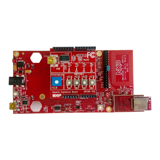
As indicated above, each Carrier Board is supplied pre-fitted with a JN5179 module with integrated antenna and an expansion board. Figure 18 below shows a pre-assembled board fitted with a Generic Expansion Board (DR1199). Figure 18: Carrier Board Fitted with Module and DR1199 Expansion Board © NXP Semiconductors 2017 JN-UG-3121 v1.1... - Page 49 JN517x-DK005 Development Kit User Guide Figure 19 below shows a pre-assembled board fitted with a Lighting/Sensor Expansion Board (DR1175). Figure 19: Carrier Board Fitted with Module and DR1175 Expansion Board The expansion boards are described in Appendix A.2, Appendix A.3 Appendix A.4.
-
Page 50: Lighting/Sensor Expansion Boards
Reset button (to reset the Carrier Board) Caution: The LEDs on the Lighting/Sensor Expansion Board are very bright at maximum intensity. To avoid damage to your eyes, do not look into them directly for an extended period of time. © NXP Semiconductors 2017 JN-UG-3121 v1.1... - Page 51 JN517x-DK005 Development Kit User Guide Sensors Prototype Area Temp/ Light Humidity Sensor Sensor LED Lighting Multi-Colour LED Module White LEDs RESET D1, D2, D3 DR1175 Figure 20: Lighting/Sensor Expansion Board Layout Figure 21: Lighting/Sensor Expansion Board JN-UG-3121 v1.1 © NXP Semiconductors 2017...
-
Page 52: Generic Expansion Boards
PCB pads for 4-way GPIO header (3V3, VCC, DIO14, DIO15), where DIO14 and DIO15 can be used to access JN517x UART1 (in this case, the FTDI driver chip for the USB port must be isolated by removing resistors R11 and R12). © NXP Semiconductors 2017 JN-UG-3121 v1.1... - Page 53 JN517x-DK005 Development Kit User Guide FTDI GPIO Chip Port Potentiometer Figure 22: Generic Expansion Board Layout Figure 23: Generic Expansion Board JN-UG-3121 v1.1 © NXP Semiconductors 2017...
-
Page 54: Jn5179 Modules
The JN5179 USB Dongle has the following features: JN5179-001 wireless microcontroller (mounted directly on the board) Integrated PCB antenna FTDI FT232 driver chip for USB connection Two LEDs (one green, one orange) © NXP Semiconductors 2017 JN-UG-3121 v1.1... - Page 55 JN517x-DK005 Development Kit User Guide Figure 24: JN5179 USB Dongle Note: The JN5179 USB Dongle is also available to purchase separately (part number OM15021). See “Optional Components” on page The two dongles are pre-programmed with different software, as described below. The...
-
Page 56: Raspberry Pi
Note: Any two of the three components must be at least 20 cm apart, and the USB dongle and Wi-Pi adaptor should be roughly perpendicular to each other Figure 25: Raspberry Pi Board and Accessories © NXP Semiconductors 2017 JN-UG-3121 v1.1... - Page 57 JN517x-DK005 Development Kit User Guide Note the following: The ‘USB to Micro USB’ cable allows the board to be powered from a USB port on the 5V DC PSU. The Raspberry Pi must be located near to the mains outlet socket in which the PSU is plugged and the PSU/socket must be easily accessible.
-
Page 58: Nfc Controller
Appendices A.7 NFC Controller The NXP PN7120 NFC Controller is supplied in the JN517x-DK005 Development Kit to facilitate NFC commissioning (see Section 1.4.1), allowing an NFC tag on a Carrier Board to be read. The NFC Controller is supplied pre-mounted on a Raspberry Pi Interface Board. - Page 59 JN517x-DK005 Development Kit User Guide For more information and operational instructions relating to the NFC Controller, refer to the following NXP documentation: AN11646: PN7120 NFC Controller SBC Kit Quick Start Guide UM10878: PN7120 NFC Controller SBC Kit User Manual The above documents can be obtained from the NXP web site.
-
Page 60: Installing A Packet Sniffer
Run the downloaded installer and follow the on-screen installation instructions 4. Start the Ubiqua Protocol Analyzer (ensure that the PC is connected to the Internet). User documentation for the Ubiqua Protocol Analyzer is available from the above Ubiqua web site. © NXP Semiconductors 2017 JN-UG-3121 v1.1... -
Page 61: Firmware Re-Programming
JN517x-DK005 Development Kit User Guide C. Firmware Re-programming The following components of the JN517x-DK005 Development Kit can be programmed with application binaries as described in this section: JN5179 modules - see Appendix C.1 JN5179 USB dongles - see Appendix C.2... -
Page 62: Installing The Ftdi Device Driver For Usb Connections
Download the required driver to your desktop and double-click on its icon to install. To perform the installation, a device or cable containing an FTDI chip must be connected to a USB port of your PC. © NXP Semiconductors 2017 JN-UG-3121 v1.1... -
Page 63: Regulatory Information
E.1 FCC Regulatory Statements The following Federal Communication Commission (FCC) regulatory statements apply to the contents for the JN517x-DK005 Development Kit. This device complies with Part 15 of the FCC Rules. Operation is subject to the following two conditions: (1) this device may not cause harmful interference, and (2) this device must accept any interference received, including interference that may cause undesired operation. - Page 64 Appendices © NXP Semiconductors 2017 JN-UG-3121 v1.1...
- Page 65 JN517x-DK005 Development Kit User Guide Revision History Version Date Comments 13-Oct-2016 First release 8-Feb-2017 Minor updates and improvements made, including new web addresses for LPCXpresso and JN517x certification information JN-UG-3121 v1.1 © NXP Semiconductors 2017...
- Page 66 NXP Semiconductors does not accept any liability related to any default, damage, costs or problem which is based on any weakness or default in the customer's applications or products, or the application or use by customer's third party customer(s).
- Page 67 Mouser Electronics Authorized Distributor Click to View Pricing, Inventory, Delivery & Lifecycle Information: OM15021,596 JN517X-XK040,598 JN517X-DK005,596 JN517X-XK030,598...
Need help?
Do you have a question about the JN517x-DK005 and is the answer not in the manual?
Questions and answers