Endress+Hauser Levelflex FMP56 Operating Instructions Manual
Guided level-radar
Hide thumbs
Also See for Levelflex FMP56:
- Operating instructions manual (218 pages) ,
- Technical information (102 pages) ,
- Brief operating instructions (60 pages)
Table of Contents
Advertisement
Quick Links
Brief Operating Instructions
Levelflex FMP56, FMP57
Guided Level-Radar
These Instructions are Brief Operating Instructions; they do not replace the
Operating Instructions included in the scope of supply.
For detailed information, refer to the Operating Instructions and other
documentation on the CD-ROM provided or visit "www.endress.com/
deviceviewer".
KA01073F/00/EN/13.12
71206500
Advertisement
Table of Contents

Related Manuals for Endress+Hauser Levelflex FMP56


Summary of Contents for Endress+Hauser Levelflex FMP56
- Page 1 Brief Operating Instructions Levelflex FMP56, FMP57 Guided Level-Radar These Instructions are Brief Operating Instructions; they do not replace the Operating Instructions included in the scope of supply. For detailed information, refer to the Operating Instructions and other documentation on the CD-ROM provided or visit "www.endress.com/ deviceviewer".
-
Page 2: Table Of Contents
Table of contents Levelflex FMP56, FMP57 Table of contents 1 Important document information ....... -
Page 3: Important Document Information
Levelflex FMP56, FMP57 Important document information Important document information Document conventions 1.1.1 Safety symbols in preparation 1.1.2 Electrical symbols Symbol Meaning Direct current A terminal to which DC voltage is applied or through which direct current flows. A0011197 Alternating current... -
Page 4: Basic Safety Instructions
The manufacturer is not liable for damage caused by improper or non-designated use. Verification for borderline cases: For special measured materials and cleaning agents, Endress+Hauser is glad to provide ► assistance in verifying the corrosion resistance of wetted materials, but does not accept any warranty or liability. -
Page 5: Workplace Safety
It fulfills general safety requirements and legal requirements. It also conforms to the EC directives listed in the device-specific EC declaration of conformity. Endress+Hauser confirms this fact by applying the CE mark. Endress+Hauser... -
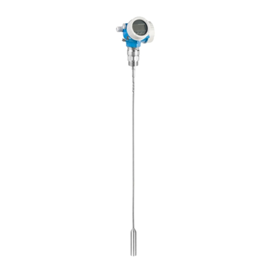
Page 6: Product Description
Product description Levelflex FMP56, FMP57 Product description Compact device Levelflex A0012470 Design of the Levelflex å 1 Electronics housing Process connection (here as an example: flange) Rope probe End-of-probe weight Rod probe Endress+Hauser... -
Page 7: Electronics Housing
Levelflex FMP56, FMP57 Product description Electronics housing A0012422 Design of the electronics housing å 2 Electronics compartment cover Display module Main electronics module Cable glands (1 or 2, depending on instrument version) Nameplate I/O electronics module Terminals (pluggable spring terminals) -
Page 8: Incoming Acceptance And Product Identification
Incoming acceptance and product identification Levelflex FMP56, FMP57 Incoming acceptance and product identification Incoming acceptance DELIVERY NOTE 1 = 2 A0013696 A0016870 A0013921 A0013922 A0013696 Endress+Hauser... -
Page 9: Product Identification
A0013696 A0014038 A0013696 A0014037 If one of the conditions does not comply, contact your Endress+Hauser distributor. Product identification The following options are available for identification of the measuring device: • Nameplate specifications • Order code with breakdown of the device features on the delivery note •... -
Page 10: Storage, Transport
Storage, Transport Levelflex FMP56, FMP57 Order code: Ser. no.: Ext. ord. cd.: A0014103 Example of a nameplate å 3 Order code Serial number (Ser. no.) Extended order code (Ext. ord. cd.) Only 33 digits of the extended order code can be indicated on the nameplate. If the extended order code exceeds 33 digits, the rest will not be shown. - Page 11 Levelflex FMP56, FMP57 Storage, Transport A0013920 A0014264 Endress+Hauser...
-
Page 12: Mounting
Mounting Levelflex FMP56, FMP57 Mounting Suitable mounting position A0012851-EN 6.1.1 Mounting distances • Distance (A) between wall and rod or rope probe: – for smooth metallic walls: > 50 mm (2") – for plastic walls: > 300 mm (12") mm to metallic parts outside the vessel –... -
Page 13: Notes On The Process Connection
Levelflex FMP56, FMP57 Mounting 6.1.2 Additional conditions • When mounting in the open, a weather protection cover (1) may be installed to protect the device against extreme weather conditions. • In metallic vessels: Preferably do not mount the probe in the center of the vessel (2), as this would lead to increased interference echoes. - Page 14 Mounting Levelflex FMP56, FMP57 Seal The thread as well as the type of seal comply to DIN 3852 Part 1, screwed plug form A. They can be sealed with the following types of sealing rings: • Thread G3/4": According to DIN 7603 with the dimensions 27 x 32 mm •...
- Page 15 Levelflex FMP56, FMP57 Mounting With thermally insulated vessels the nozzle should also be insulated in order to prevent condensate formation. Rod extension/centering HMP40 for FMP57 For FMP57 with rope probes the rod extension/centering HMP 40 is available as an accessory (Verweisziel existiert nicht, aber @y.link.required='true').
-
Page 16: Securing The Probe
Mounting Levelflex FMP56, FMP57 Securing the probe 6.3.1 Securing rope probes A0012609 Sag of the rope: ³ 1 cm per 1m of the probe length (0.12 inch per 1 ft of the probe length) Reliably grounded end of probe Reliably isolated end of probe... - Page 17 Levelflex FMP56, FMP57 Mounting 6.3.2 Securing rod probes • For Ex-approvals: For probe lengths ³ 3 m (10 ft) a support is required. • In general, rod probes must be supported if there is a horizontal flow (e.g. from an agitator) or in the case of strong vibrations.
-
Page 18: Special Mounting Conditions
Mounting Levelflex FMP56, FMP57 NOTICE Poor grounding of the end of probe may cause measuring errors. Apply a narrow sleeve which has good electrical contact to the probe. ► NOTICE Welding may damage the main electronics module. Before welding: Ground the probe and dismount electronics. - Page 19 Levelflex FMP56, FMP57 Mounting • To shorten rope probes: – Allen key AF 3 mm (for 4mm ropes) or AF 4 mm (for 6 mm ropes) – Saw or bolt cutter • For flanges and other process connections: appropriate mounting tools •...
- Page 20 Mounting Levelflex FMP56, FMP57 4 / 6 mm 0.16 / 0.25 inch 5/15 Nm A0012453 1. Loosen the 3 Allen set screws using an Allen key AF3 (for 4mm ropes) or AF4 (for 6 mm ropes). Note: The set screws have got a clamping coating in order to prevent accidental loosening.
- Page 21 Levelflex FMP56, FMP57 Mounting 6.5.3 Mounting the device Mounting devices with thread A0012528 Devices with mounting thread are screwed into a welding boss or a flange and are usually also secured with these. • Tighten with the hexagonal nut only: –...
- Page 22 Mounting Levelflex FMP56, FMP57 A0012529 When lowering the rope probe into the vessel, observe the following: • Uncoil rope and lower it slowly and carefully into the vessel. • Do not kink the rope. • Avoid any backlash, since this might damage the probe or the vessel fittings.
- Page 23 Levelflex FMP56, FMP57 Mounting max. 350° 8 mm 8 mm A0013713 1. Unscrew the securing screw using an open-ended wrench. 2. Rotate the housing in the desired direction. 3. Firmly tighten the securing screw. (1,5 Nm for plastics housing; 2,5 Nm for aluminium or stainless steel housing).
-
Page 24: Post-Installation Check
Mounting Levelflex FMP56, FMP57 7. Tighten the securing clamp again using the Allen key. Post-installation check Is the device undamaged (visual inspection)? Does the device conform to the measuring point specifications? For example: • Process temperature • Process pressure (refer to the chapter on "Material load curves" of the "Technical Information"... -
Page 25: Electrical Connection
Levelflex FMP56, FMP57 Electrical connection Electrical connection Connection options 7.1.1 Connection options PROFIBUS PA / FOUNDATION Fieldbus A0011341 Terminal assignment PROFIBUS PA / FOUNDATION Fieldbus å 5 Without integrated overvoltage protection With integrated overvoltage protection Cable screen: Observe cable specifications (® ä 27) - Page 26 Electrical connection Levelflex FMP56, FMP57 Terminal for potential equalization line Cable entries Overvoltage protection module Endress+Hauser...
-
Page 27: Connection Options
Levelflex FMP56, FMP57 Electrical connection Connection examples for the switch output For HART devices, the switch output is available as an option. See product structure, feature 20: "Power Supply, Output", option B: "2-wire; 4-20mA HART, switch output" Devices with PROFIBUS PA and FOUNDATION Fieldbus always have a switch output. -
Page 28: Connection Data
< 1.5 pF Nominal arrest impulse voltage (8/20 ms) 10 kA External overvoltage protection HAW562 or HAW569 from Endress+Hauser are suited as external overvoltage protection. For detailed information please refer to the following documents: • HAW562: TI01012K • HAW569: TI01013K Connection data 7.3.1... -
Page 29: Connecting The Measuring Device
Levelflex FMP56, FMP57 Electrical connection Connecting the measuring device WARNING Explosion hazard! Comply with the relevant national standards. ► Observe the specifications in the Safety Instructions (XA). ► Only use the specified cable glands. ► Check whether the supply voltage matches the specifications on the nameplate. - Page 30 Electrical connection Levelflex FMP56, FMP57 A0013837 Connect the cable in accordance with the terminal assignment (® ä 25). 8. When using screened cable: Connect the cable screen to the ground terminal. 9. Screw the cover onto the connection compartment. 10. For instruments with safety pin for the lid: Adjust the safety pin so that its edge is over the edge of the display lid.
- Page 31 Levelflex FMP56, FMP57 Electrical connection ≤ 3 (0.12) mm (in) A0013661 Endress+Hauser...
-
Page 32: Post-Connection Check
Integration into a PROFIBUS network Levelflex FMP56, FMP57 Post-connection check Are cables or the device undamaged (visual inspection)? Do the cables comply with the requirements? Do the cables have adequate strain relief? Are all cable glands installed, firmly tightened and correctly sealed? Does the supply voltage match the specifications on the transmitter nameplate? Is the terminal assignment correct (®... -
Page 33: Set Device Address
Levelflex FMP56, FMP57 Integration into a PROFIBUS network Set device address A0015686 Address switches in terminal compartment å 8 8.2.1 Hardware adressing 1. Set switch 8 to "OFF". 2. Define the address with switches 1 to 7 according to the table below. - Page 34 Integration into a PROFIBUS network Levelflex FMP56, FMP57 A0015903 Example of software addressing; switch 8 is in position "ON"; the address is defined in the å 10 operating menu (Setup ® Device address) Endress+Hauser...
-
Page 35: Commissioning Via Operating Menu (On-Site Display, Fieldcare)
Levelflex FMP56, FMP57 Commissioning via operating menu (On-site display, FieldCare) Commissioning via operating menu (On-site display, FieldCare) Display and operating module 9.1.1 Display appearance User ABC_ DEFG HIJK LMNO PQRS TUVW A0012635 Appearance of the display and operation module for on-site operation å... - Page 36 Commissioning via operating menu (On-site display, FieldCare) Levelflex FMP56, FMP57 9.1.2 Navigation and selection from a list Use the operating keys to navigate within the operating menu and to select options from a list. Meaning "Minus" key Henceforth represented by S.
-
Page 37: Operating Concept
Levelflex FMP56, FMP57 Commissioning via operating menu (On-site display, FieldCare) Operating concept 9.2.1 Structure Language Display/operation Parameter 1 Parameter 2 Parameter N Setup Setup parameter 1 Setup parameter 2 Setup parameter N Advanced setup Enter access code Parameter 1 Parameter N... - Page 38 Commissioning via operating menu (On-site display, FieldCare) Levelflex FMP56, FMP57 9.2.2 Submenus and user roles The submenus are designed for different user roles. A user role is defined by typical tasks within the lifecycle of the device. User role Typical tasks...
-
Page 39: Adjust The Display Contrast
Levelflex FMP56, FMP57 Commissioning via operating menu (On-site display, FieldCare) Adjust the display contrast • O + F (pressed simultaneously): increases the contrast. • S + F (pressed simultaneously): decreases the contrast. Unlock the device If the device has been locked, it must be unlocked before the measurement can be configured. - Page 40 Commissioning via operating menu (On-site display, FieldCare) Levelflex FMP56, FMP57 1. Unscrew the lid from the compartment for the display and operating module. 2. Slightly turn the display and operating module to remove it from the compartment. 3. Set the locking switch (WP: Write Protection) into the desired position. (A): unlocked;...
-
Page 41: Set The Operating Language
Levelflex FMP56, FMP57 Commissioning via operating menu (On-site display, FieldCare) Set the operating language A0013637 Endress+Hauser... -
Page 42: Configuration Of A Level Measurement
Commissioning via operating menu (On-site display, FieldCare) Levelflex FMP56, FMP57 Configuration of a level measurement 100% A0012838 Configuration parameters for level measurements in solids å 15 LN = Length of probe R = Reference point of the measurement D = Distance... -
Page 43: User-Specific Applications (Operation)
Levelflex FMP56, FMP57 Commissioning via operating menu (On-site display, FieldCare) User-specific applications (operation) For details of setting the parameters of user-specific applications, see separate documentation: • Operator and Maintenance ® BA01009F/00/EN (Operating Instructions) • Experte ® GP01001F/00/EN (Description of Device Parameters) - Page 44 *71206500* KA01073F/00/EN/13.12 71206500 71206500 CCS/COSIMA...
Need help?
Do you have a question about the Levelflex FMP56 and is the answer not in the manual?
Questions and answers