
Related Manuals for Emerson Rosemount 3095


Summary of Contents for Emerson Rosemount 3095
- Page 1 Reference Manual 00809-0100-4716, Rev JA May 2008 ™ Rosemount 3095 MultiVariable Mass Flow ® ™ Transmitter with HART or F OUNDATION Fieldbus Protocol www.rosemount.com...
-
Page 3: Table Of Contents
Reference Manual 00809-0100-4716, Rev JA Rosemount 3095 MultiVariable May 2008 Table of Contents SECTION 1 Using This Manual ........1-1 Service Support . - Page 4 Reference Manual 00809-0100-4716, Rev JA Rosemount 3095 MultiVariable May 2008 SECTION 3 Safety Messages ......... 3-1 Engineering Assistant Software.
- Page 5 Reference Manual 00809-0100-4716, Rev JA Rosemount 3095 MultiVariable May 2008 SECTION 5 Safety Messages ......... 5-1 EA Communication Troubleshooting .
- Page 6 Reference Manual 00809-0100-4716, Rev JA Rosemount 3095 MultiVariable May 2008 APPENDIX B Approved Manufacturing Locations ......B-1 European Directive Information .
- Page 7 Reference Manual 00809-0100-4716, Rev JA Rosemount 3095 MultiVariable May 2008 Rosemount 3095 MultiVariable Mass Flow Transmitter NOTICE Read this manual before working with the product. For personal and system safety, and for optimum product performance, make sure you thoroughly understand the contents before installing, using, or maintaining this product.
-
Page 9: Using This Manual
Reference Manual 00809-0100-4716, Rev JA Rosemount 3095 MultiVariable May 2008 Section 1 Introduction Using This Manual ....... page 1-1 Service Support . -
Page 10: Service Support
Reference Manual 00809-0100-4716, Rev JA Rosemount 3095 MultiVariable May 2008 SERVICE SUPPORT To expedite the return process outside the United States, contact the nearest Rosemount representative. Within the United States, call the Rosemount National Response Center using the 1-800-654-RSMT (7768) toll-free number. This center, available 24 hours a day, will assist you with any needed information or materials. -
Page 11: Safety Messages
Reference Manual 00809-0100-4716, Rev JA Rosemount 3095 MultiVariable May 2008 Section 2 Installation Safety Messages ....... . . page 2-1 Installation Flowchart . -
Page 12: Installation Flowchart
Reference Manual 00809-0100-4716, Rev JA Rosemount 3095 MultiVariable May 2008 INSTALLATION FLOWCHART FIELD START INSTALLATION Unpack the Review Installation 3095 BENCH CONFIGURE Considerations Connect Bench Mount Review the Power Supply Transmitter 3095 Manual Review Rosemount drawing 03095-1025 Connect a Personal... -
Page 13: Set The Switches
Review the packing list to verify that all equipment was received. • Inspect the equipment and report any shipping damage to the carrier. • See “Exploded View of the Rosemount 3095” on page A-9 to verify parts SET THE SWITCHES Write Protect and Failure After the transmitter has been configured, the configuration data can be protected by moving the write protect jumper. -
Page 14: Security And Simulate Jumpers
Reference Manual 00809-0100-4716, Rev JA Rosemount 3095 MultiVariable May 2008 If the transmitter is installed, secure the loop and remove power. Remove the housing cover opposite the field terminal side. Locate the jumper on the electronics board (see Figure 2-1), then move the jumper to the desired setting. -
Page 15: Mechanical
Rosemount 3095 MultiVariable May 2008 Mechanical The Rosemount 3095 may be panel-mounted, wall-mounted, or attached to a two-inch pipe with an optional mounting bracket. Figure 2-2 illustrates 3095 mounting configurations, “Dimensional Drawings” on page A-9 shows the transmitter dimensions, and Figure 2-3 illustrates example installations. -
Page 16: Impulse Piping
Reference Manual 00809-0100-4716, Rev JA Rosemount 3095 MultiVariable May 2008 In steam or other elevated temperature services, it is important that temperatures at the coplanar process flanges not exceed 185 °F (85 °C). Figure 2-3. Example Installations. STEAM Flow SERVICE... -
Page 17: Environmental
Reference Manual 00809-0100-4716, Rev JA Rosemount 3095 MultiVariable May 2008 The best location for the transmitter in relation to the process pipe depends on the process. Consider the following guidelines in determining transmitter location and placement of impulse piping: •... -
Page 18: Process
Reference Manual 00809-0100-4716, Rev JA Rosemount 3095 MultiVariable May 2008 Housing Rotation The electronics housing may be rotated to improve field access to the two compartments. To rotate the housing less than 90 degrees, release the housing rotation set screw and turn the housing not more than 90 degrees from the orientation shown in Figure 2-3 on page 2-6. - Page 19 Reference Manual 00809-0100-4716, Rev JA Rosemount 3095 MultiVariable May 2008 Failure to install proper flange adapter O-rings can cause process leaks, which can result in death or serious injury. There are two styles of Rosemount flange adapters, each requiring a unique O-ring, as shown below.
-
Page 20: Mounting
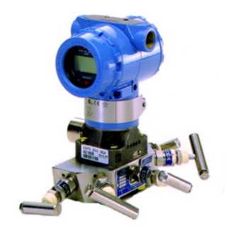
Reference Manual 00809-0100-4716, Rev JA Rosemount 3095 MultiVariable May 2008 Mounting Figure 2-4 illustrates a typical 3095 installation site. Major components of the 3095 System and the 3095 Multivariable Transmitter are identified in these figures. Figure 2-4. Typical 3095 Installation Site... -
Page 21: Bolt Installation Guidelines
Stainless Steel Head Markings (SST) Hazardous Locations The Rosemount 3095 has an explosion-proof housing and circuitry suitable for intrinsically safe and non-incendive operation. Individual transmitters are clearly marked with a tag indicating the certifications they carry. See Appendix A: Specifications and Reference Data for specific approval categories. -
Page 22: Electrical (Hart)
Reference Manual 00809-0100-4716, Rev JA Rosemount 3095 MultiVariable May 2008 Electrical (HART) The signal terminals are located in a compartment of the electronics housing separate from the transmitter electronics. Power Supply The dc power supply should provide power with less than 2% ripple. The total resistance load is the sum of the resistance of the signal leads and the load resistance of the controller, indicator, and related pieces. - Page 23 Reference Manual 00809-0100-4716, Rev JA Rosemount 3095 MultiVariable May 2008 NOTE Do not apply high voltage (e.g. ac line voltage) to the transmitter terminals. Abnormally high voltage can damage the unit. Grounding Signal wiring of the fieldbus segment cannot be grounded. Grounding out one of the signal wires will shut down the entire fieldbus segment.
-
Page 24: Grounding The Transmitter Housing
Reference Manual 00809-0100-4716, Rev JA Rosemount 3095 MultiVariable May 2008 Figure 2-7. F OUNDATION Fieldbus Transmitter Terminal Block Power Terminals NOTE Do not ground out the live signal wiring to the housing when working on a segment. Grounding the communication wires may result in temporary loss of communication with all devices on the segment. -
Page 25: Optional Transient Protection Terminal Block
Reference Manual 00809-0100-4716, Rev JA Rosemount 3095 MultiVariable May 2008 Optional Transient The transient terminal block can be ordered as an installed option (Option Code T1 in the transmitter model number) or as a spare part to retrofit existing Protection Terminal 3095 transmitters in the field. -
Page 26: Process Connections
Reference Manual 00809-0100-4716, Rev JA Rosemount 3095 MultiVariable May 2008 Table 2-2. Bolt Installation Torque Values. Bolt Material Initial Torque Value Final Torque Value Carbon Steel (CS) 300 in-lb (34 n-m) 650 in-lb (73 n-m) Stainless Steel (SST) 150 in-lb (17 n-m) -
Page 27: Install Rtd Assembly (Optional)
Reference Manual 00809-0100-4716, Rev JA Rosemount 3095 MultiVariable May 2008 Install RTD Assembly (Optional) Install the Series 68 or Series 78 RTD Assembly. (optional) NOTE To meet ISSep/CENELEC Flameproof certification, only European Flameproof Cable Assemblies (Process Temperature Input Codes A, B, or C) may be used for RTD cable installation. - Page 28 Reference Manual 00809-0100-4716, Rev JA Rosemount 3095 MultiVariable May 2008 • Installing a Shielded 3095 RTD Cable (intended for use in a conduit) a. Fully engage the black cable connector to the 3095 RTD Connector (see Figure 2-9). b. Tighten the cable adapter until metal contacts metal (see Figure 2-9).
-
Page 29: Check For Leaks
Reference Manual 00809-0100-4716, Rev JA Rosemount 3095 MultiVariable May 2008 Check for Leaks Check all process penetrations for leaks. Power and Signal Wiring Make field wiring connections (see Figure 2-6 or Figure 2-12). These connections provide both power and signal wiring. - Page 30 Reference Manual 00809-0100-4716, Rev JA Rosemount 3095 MultiVariable May 2008 Figure 2-12. HART Wiring Connections. 1100 > R > 250 User-Provided Power Supply (see step 7.b) Signal loop may be grounded at any point or left ungrounded (see step 7.a).
-
Page 31: Safety Messages
Reference Manual 00809-0100-4716, Rev JA Rosemount 3095 MultiVariable May 2008 Section 3 HART Commissioning Safety Messages ....... . . page 3-1 Engineering Assistant Software . -
Page 32: Engineering Assistant Software
Reference Manual 00809-0100-4716, Rev JA Rosemount 3095 MultiVariable May 2008 ENGINEERING The 3095 Engineering Assistant (EA) Software is a PC-based software package. The EA Software lets you configure the 3095 Multivariable Mass ASSISTANT SOFTWARE Flow Transmitter and 3095 Multivariable Mass Flowmeters. - Page 33 Reference Manual 00809-0100-4716, Rev JA Rosemount 3095 MultiVariable May 2008 Installing the HART Modem After the EA Software has been installed, the HART modem device driver must be installed and configured. The HART modem Installation Wizard automatically appears when the 3095 EA Software is launched. If the wizard does not automatically launch, you can configure the modem by accessing the AMS Network Configuration screen.
- Page 34 Reference Manual 00809-0100-4716, Rev JA Rosemount 3095 MultiVariable May 2008 Specify a name for the HART Modem. The default is “HART Modem 1.” Click “Next.” Specify whether AMS will act as a primary or secondary HART master for configuration (See Figure 3-2). If performing a bench configuration, it is recommended to choose “Hand held device as a...
- Page 35 Reference Manual 00809-0100-4716, Rev JA Rosemount 3095 MultiVariable May 2008 Connecting to a Personal Computer Figure 3-3 shows how to connect a computer to a 3095. Figure 3-3. Connecting a PC to the 3095 1100 > R > 250 User-Provided...
- Page 36 Reference Manual 00809-0100-4716, Rev JA Rosemount 3095 MultiVariable May 2008 a. For AMS Snap-On users: 1. Click on the Windows “Start” button. 2. Click on “All Programs.” 3. Click on the “AMS” folder. 4. Click on the “AMS System” icon.
-
Page 37: Basic Navigation
Reference Manual 00809-0100-4716, Rev JA Rosemount 3095 MultiVariable May 2008 Figure 3-5. Device Connection View Basic Navigation The 3095 Engineering Assistant lets you navigate through the software in a variety of ways. When first logging onto the system, the default screen is the Device Connection View (Figure 3-5). -
Page 38: Procedures
Reference Manual 00809-0100-4716, Rev JA Rosemount 3095 MultiVariable May 2008 Tool Bar Another fast way to navigate through the 3095 Engineering Assistance Software is by using the toolbar (see Figure 3-6). Figure 3-6. Toolbar Icons Procedures In both Snap-On and Stand-Alone versions of the 3095 Engineering Assistant Software, most of the device parameters can be accessed by right-clicking on the transmitter icon (See Figure 3-7 below). - Page 39 Reference Manual 00809-0100-4716, Rev JA Rosemount 3095 MultiVariable May 2008 Figure 3-7. Transmitter Links...
- Page 40 Reference Manual 00809-0100-4716, Rev JA Rosemount 3095 MultiVariable May 2008 Process Variables… The “Process Variables…” link displays the current reading of the process variables measured by the 3095. In the “Process Variables…” window, variables are automatically updated every 2-3 seconds. All values on the screen are read-only.
- Page 41 Reference Manual 00809-0100-4716, Rev JA Rosemount 3095 MultiVariable May 2008 Status… The “Status…” link displays a list of the transmitter errors, alarms, and failures. If a status flag is triggered, it is highlighted in red. Right-click on the transmitter icon.
- Page 42 Reference Manual 00809-0100-4716, Rev JA Rosemount 3095 MultiVariable May 2008 Right-click on the transmitter icon. Highlight “Diagnostics and Tests” from the pop-up menu. Select “Loop Test” from the submenu. Read the warning message and click “Next.” Select the analog output level for the transmitter and click “Next.” If “Other”...
- Page 43 Reference Manual 00809-0100-4716, Rev JA Rosemount 3095 MultiVariable May 2008 Figure 3-11. Sensor Trim Menu In addition to the 3095 EA software, the following equipment is required for a sensor trim procedure: • 3095 transmitter • Dead-weight tester • Power supply and load resistor •...
- Page 44 Reference Manual 00809-0100-4716, Rev JA Rosemount 3095 MultiVariable May 2008 Sensor Trim Procedure Right-click on the transmitter icon. Select “Process Variables” to view measured variables and determine if a sensor trim is needed (see Figure 3-8). Right-click on the transmitter icon. Select “Calibrate/Sensor Trim”...
- Page 45 Reference Manual 00809-0100-4716, Rev JA Rosemount 3095 MultiVariable May 2008 c. To restore the selected process variable to its factory default calibration, select “Factory Trim Recall” and click “Next.” 1. Read the warning message and click “Next.” 2. Select “Yes” to implement the default calibration, and click “Next.”...
- Page 46 Reference Manual 00809-0100-4716, Rev JA Rosemount 3095 MultiVariable May 2008 Changing the Atmospheric Pressure Value: The Gauge Sensor on the 3095 takes measurements with respect to the atmospheric pressure. To change the assumed atmospheric pressure value: Right-click on the transmitter icon.
- Page 47 Reference Manual 00809-0100-4716, Rev JA Rosemount 3095 MultiVariable May 2008 D/A Trim The D/A Trim allows the user to adjust the digital-to-analog converter at the end points of the transmitter output scale to compensate for a discrepancy with a reference milliamp meter.
- Page 48 Reference Manual 00809-0100-4716, Rev JA Rosemount 3095 MultiVariable May 2008 Scaled D/A Trim For the Scaled D/A Trim, the user can adjust the transmitter digital-to-analog converter on an alternate unit of measure, such as voltage (example: using a voltmeter across a 500 ohm resistor produces a low point of 2 volts a high point of 10V).
- Page 49 Reference Manual 00809-0100-4716, Rev JA Rosemount 3095 MultiVariable May 2008 Process Variable Assignments The “Assignments” (or Process Variable Assignments) link lets you assign specific variables to individual 4-20mA loops for use with the Rosemount 333 HART Tri-Loop. Table 3-1 illustrates the default variables assigned to each control loop.
- Page 50 Reference Manual 00809-0100-4716, Rev JA Rosemount 3095 MultiVariable May 2008 RTD Configuration The RTD Config link specifies the process temperature (PT) mode. It allows you to enable or disable PT input or to specify automatic backup mode. When in Normal Mode, the transmitter uses the external RTD for PT measurement.
-
Page 51: Differential Pressure (Dp)
Reference Manual 00809-0100-4716, Rev JA Rosemount 3095 MultiVariable May 2008 DP Low Flow Cutoff The DP Low Flow Cutoff screen allows the minimum differential pressure (DP) limit for the 3095 to calculate flow to be set. At a DP value less than the low flow cutoff, the flow value will equal zero. - Page 52 Reference Manual 00809-0100-4716, Rev JA Rosemount 3095 MultiVariable May 2008 Rename To change the name that appears next to the transmitter icon on the 3095 Engineering Assistant software: Right-click on the transmitter icon. Click “Rename” from the pop-up menu. Type a new name for the transmitter, and press “Enter” on the keyboard.
- Page 53 Reference Manual 00809-0100-4716, Rev JA Rosemount 3095 MultiVariable May 2008 Figure 3-18. Compare Configurations 3-23...
- Page 54 Reference Manual 00809-0100-4716, Rev JA Rosemount 3095 MultiVariable May 2008 Configuration Properties… The Configuration Properties screen contains device parameters that are grouped into tabs located at the top of the window. To access the Configuration Properties window: Right-click on the transmitter icon.
- Page 55 Reference Manual 00809-0100-4716, Rev JA Rosemount 3095 MultiVariable May 2008 Device Tab The device tab provides more in-depth information about the 3095 transmitter. Only the Date, Descriptor, and Message fields can be edited. All other fields on the Device tab are read only: •...
- Page 56 Reference Manual 00809-0100-4716, Rev JA Rosemount 3095 MultiVariable May 2008 HART Tab The HART tab is used to set some of the communications parameters that are used by HART protocol. • Tag: same parameter as found on the “Basic Setup” tab.
- Page 57 Reference Manual 00809-0100-4716, Rev JA Rosemount 3095 MultiVariable May 2008 Figure 3-21. HART Tab DP Sensor Tab The DP Sensor screen provides read only information about the DP sensor module (see Figure 3-22). • Flange Type: From the drop-down menu, select the flange type used in the primary assembly •...
- Page 58 Reference Manual 00809-0100-4716, Rev JA Rosemount 3095 MultiVariable May 2008 Flow Tab The Flow Tab allows for the configuration of flow damping and units of measure (see Figure 3-23). • Flow USL and Flow LSL: This is a value calculated by the transmitter.
- Page 59 Reference Manual 00809-0100-4716, Rev JA Rosemount 3095 MultiVariable May 2008 LCD Configuration Tab The following parameters can be displayed on the LCD (if LCD is ordered and installed on transmitter). See Figure 3-24. • Differential Pressure • Static Pressure (Absolute Pressure) •...
- Page 60 Reference Manual 00809-0100-4716, Rev JA Rosemount 3095 MultiVariable May 2008 Figure 3-25. Flow Total Process Input Tab On the Process Input tab, the units of measure and damping can be configured for each of the measured variables (DP, AP/GP, and Temp).
- Page 61 Reference Manual 00809-0100-4716, Rev JA Rosemount 3095 MultiVariable May 2008 Analog Output Tab • Upper Range Value (URV) and Lower Range Value (LRV): Sets the range represented by the 4 to 20mA output. These functions are also selectable on the “Basic Setup” tab.
- Page 62 Reference Manual 00809-0100-4716, Rev JA Rosemount 3095 MultiVariable May 2008 Spec Units Tab The Special Units tab configures flow measurement and flow total to be displayed in units considered nonstandard in the 3095M transmitter. NOTE After completing a special unit configuration, reset the 4-20mA range (LRV and URV).
-
Page 63: Set Up Tri-Loop Configuration
Reference Manual 00809-0100-4716, Rev JA Rosemount 3095 MultiVariable May 2008 Set up Tri-loop Start AMS. Configuration Right-click the on-line 3095 and select Configuration Properties. Select the HART tab. Select Burst Mode Off. Select Burst option to processvars/crnt. This is HART command 3. - Page 64 Reference Manual 00809-0100-4716, Rev JA Rosemount 3095 MultiVariable May 2008 Figure 3-29. 3095 Engineering Assistant Menu Structure. Basic Navigation File Menu “New” starts with a fresh configuration file. This should be selected before import and opening a file. “Open” lets you open a previously saved configuration file.
- Page 65 Reference Manual 00809-0100-4716, Rev JA Rosemount 3095 MultiVariable May 2008 Transmitter Menu Use “Send Configuration…” to fully implement the flow configuration to the transmitter. When finished with the flow configuration wizard, the transmitter does not use the new configuration until the “Send Configuration…” link is used.
-
Page 66: Physical
Reference Manual 00809-0100-4716, Rev JA Rosemount 3095 MultiVariable May 2008 Flow Configuration Wizard The flow configuration wizard screens are used to define compensated flow parameters and to create flow configuration files for sending to a transmitter. The flow configuration wizard can be launched by clicking on the “Configure Flow”... - Page 67 Reference Manual 00809-0100-4716, Rev JA Rosemount 3095 MultiVariable May 2008 Process Fluid Selection The first screen of the flow configuration wizard lets you select the process fluid used in your application. Available fluids include: • Natural Gas (AGA & ISO) •...
-
Page 68: Options
Reference Manual 00809-0100-4716, Rev JA Rosemount 3095 MultiVariable May 2008 Table 3-2. Gross vs. Detail Characterization Method Engineering Assistant Variable Gross Method Detail Method Pressure 0–1200 psia 0–20,000 psia Temperature 32 to 130 °F –200 to 400 °F Specific Gravity 0.554–0.87... - Page 69 Reference Manual 00809-0100-4716, Rev JA Rosemount 3095 MultiVariable May 2008 Gas & Liquid Flow Select either Database Gas, Database Fluid, Custom Gas, or Custom Fluid from the “Fluid Designation Category” Header. If using a database gas or fluid, select the fluid used from the “Fluid Type”...
- Page 70 Reference Manual 00809-0100-4716, Rev JA Rosemount 3095 MultiVariable May 2008 Composition Mole % (Natural Gas Only) The next screen will take you to either the gas composition table or the gross characterization screens, depending on what you selected in the previous screen.
- Page 71 Reference Manual 00809-0100-4716, Rev JA Rosemount 3095 MultiVariable May 2008 Gross Characterization Method 1 (AGA) & Physical Property: SGRG-88 (ISO) Gross Method 1 uses the density of natural gas, its heating value, and the quantity of non-hydrocarbon components to calculate the gas compressibility factor per AGA8.
- Page 72 Reference Manual 00809-0100-4716, Rev JA Rosemount 3095 MultiVariable May 2008 Primary Element Selection The Primary Element Selection Screen lets you configure the primary element used with the 3095. The following steps apply to all fluid types (gas, fluid, natural gas, steam).
- Page 73 Reference Manual 00809-0100-4716, Rev JA Rosemount 3095 MultiVariable May 2008 Table 3-4. Primary Element Options Annubar Orifice Plate ® Annubar Diamond II (Discontinued 1999) 1195 Integral Orifice ® Annubar Diamond II+ / Mass ProBar 1195 Mass ProPlate ® Calibrated Annubar...
- Page 74 Reference Manual 00809-0100-4716, Rev JA Rosemount 3095 MultiVariable May 2008 Operating & Reference Conditions After supplying information about the primary element, the next screen prompts you to enter values for environmental and operating conditions. This screen applies to all process fluids.
- Page 75 Reference Manual 00809-0100-4716, Rev JA Rosemount 3095 MultiVariable May 2008 Density, Viscosity, and Compressibility Configuration The next screen displays the calculated density and viscosity values based on entries made in previous screens in the flow configuration wizard. If a change is made to either a density or viscosity value, the 3095 EA software considers the fluid to be “Custom Fluid.”...
- Page 76 Reference Manual 00809-0100-4716, Rev JA Rosemount 3095 MultiVariable May 2008 Saving the Flow Configuration Once the flow configuration wizard is complete, you will be prompted to save the new flow configuration. You can save it on the computer’s hard disk, the 3095’s flash memory, or both.
-
Page 77: Off-Line Configuration
Reference Manual 00809-0100-4716, Rev JA Rosemount 3095 MultiVariable May 2008 Off-line Configuration In off-line mode, the 3095 Engineering Assistant does not communicate directly with the transmitter. Instead, the configuration file is saved to the computer and loaded onto the transmitter at a later time when in on-line mode. - Page 78 Reference Manual 00809-0100-4716, Rev JA Rosemount 3095 MultiVariable May 2008 Figure 3-38. Off-Line Configuration 3-48...
-
Page 79: Overview
Reference Manual 00809-0100-4716, Rev JA Rosemount 3095 MultiVariable May 2008 Section 4 Fieldbus OUNDATION Configuration Overview ........page 4-1 Safety Messages . -
Page 80: Engineering Assistant Software
Reference Manual 00809-0100-4716, Rev JA Rosemount 3095 MultiVariable May 2008 Failure to follow these installation guidelines could result in death or serious injury. • Make sure only qualified personnel perform the installation. Explosions could result in death or serious injury. - Page 81 Reference Manual 00809-0100-4716, Rev JA Rosemount 3095 MultiVariable May 2008 Install the NI-FBUS Communications Manager Driver Software from the National Instruments CD. a. Insert the NI-FBUS Communications Manager Driver CD. b. Windows should detect the presence of a CD and start the installation program.
- Page 82 Fieldbus.org web site. a. Go to Fieldbus.org. b. Click the End User Resources button. c. Click Registered Products. d. Choose Emerson Process Management from the Manufacturer drop-down menu. e. Choose Flow from the Category drop-down menu. f. Click Search.
- Page 83 Reference Manual 00809-0100-4716, Rev JA Rosemount 3095 MultiVariable May 2008 Establish Communications with the 3095 F Fieldbus OUNDATION Transmitter using 3095 EA for F Fieldbus OUNDATION Connect the 9-pin communications cable into the PCMCIA card port located in the computer.
- Page 84 Reference Manual 00809-0100-4716, Rev JA Rosemount 3095 MultiVariable May 2008 Create and Send a Mass Flow Configuration using 3095 EA for FOUNDATION Fieldbus A mass flow configuration file can be created in either OFFLINE or ONLINE mode. Select the device tag name requiring a new or updated mass flow configuration file.
- Page 85 Reference Manual 00809-0100-4716, Rev JA Rosemount 3095 MultiVariable May 2008 Figure 4-3. EA Wizard View EA Wizard Upon completing a mass flow configuration using the EA Wizard, the file can be saved to disk. The file must be saved for review or to edit the mass flow configuration file in the future.
- Page 86 Reference Manual 00809-0100-4716, Rev JA Rosemount 3095 MultiVariable May 2008 Figure 4-4. Download Mass Flow Configuration File Selected Device Send Mass Flow (Highlighted) Configuration File to Status Confirms Mass Selected Device Flow Configuration File Installations...
- Page 87 Reference Manual 00809-0100-4716, Rev JA Rosemount 3095 MultiVariable May 2008 Verify the Flow Configuration To view the flow configuration parameters: Open the Mass Flow Block. The following parameters, shown in Table 4-1, contain the flow configuration information that can be viewed in the Mass Flow Block.
-
Page 88: General Information
Reference Manual 00809-0100-4716, Rev JA Rosemount 3095 MultiVariable May 2008 GENERAL INFORMATION Device Description Before configuring the device, ensure the host has the appropriate Device Description file revision for this device. The device descriptor can be found on www.rosemount.com. The initial release of the 3095 with FOUNDATION Fieldbus protocol is device revision 1. - Page 89 Reference Manual 00809-0100-4716, Rev JA Rosemount 3095 MultiVariable May 2008 Types of Modes For the procedures described in this manual, it will be helpful to understand the following modes: AUTO The functions performed by the block will execute. If the block has any outputs, these will continue to update.
-
Page 90: Capabilities
Reference Manual 00809-0100-4716, Rev JA Rosemount 3095 MultiVariable May 2008 Capabilities Virtual Communication Relationship (VCRs) There are a total of 20 VCRs. One is permanent and 18 are fully configurable by the host system. Twenty five link objects are available. - Page 91 Reference Manual 00809-0100-4716, Rev JA Rosemount 3095 MultiVariable May 2008 Mass Flow Transducer Block (1200) Contains configuration and diagnostic information to perform fully compensated mass flow calculations. Contains the mass flow process variable (PV). Mass flow is calculated using process differential pressure and pressure.
-
Page 92: Resource Block
When fault state is set, then output function bocks will perform their FSTATE actions. The Rosemount 3095 supports fault state action. The fault state option bit must be set in the features bit to use this feature. - Page 93 Reference Manual 00809-0100-4716, Rev JA Rosemount 3095 MultiVariable May 2008 The FEATURE_SEL parameter enables the user to select a hardware or software write lock or no write lock capability. To enable the hardware security function, enable the HW_SEL bit in the FEATURE_SEL parameter. When this bit has been enabled the WRITE_LOCK parameter becomes read only and will reflect the state of the hardware switch.
-
Page 94: Plantweb ™ Alerts
Reference Manual 00809-0100-4716, Rev JA Rosemount 3095 MultiVariable May 2008 ™ PlantWeb Alerts The Resource Block will act as a coordinator for PlantWeb alerts. There will be three alarm parameters (FAILED_ALARM, MAINT_ALARM, and ADVISE_ALARM) which will contain information regarding some of the device errors which are detected by the transmitter software. - Page 95 Reference Manual 00809-0100-4716, Rev JA Rosemount 3095 MultiVariable May 2008 MAINT_ALARMS A maintenance alarm indicates the device or some part of the device needs maintenance soon. If the condition is ignored, the device will eventually fail. There are five parameters associated with MAINT_ALARMS, they are described below.
- Page 96 Reference Manual 00809-0100-4716, Rev JA Rosemount 3095 MultiVariable May 2008 Advisory Alarms An advisory alarm indicates informative conditions that do not have a direct impact on the device's primary functions There are five parameters associated with ADVISE_ALARMS, they are described below.
-
Page 97: Recommended Actions For Plantweb Alerts
Reference Manual 00809-0100-4716, Rev JA Rosemount 3095 MultiVariable May 2008 Recommended Actions RECOMMENDED_ACTION The RECOMMENDED_ACTION parameter displays a text string that will give for PlantWeb Alerts a recommended course of action to take based on which type and which specific event of the PlantWeb alerts are active. -
Page 98: Damping
The Mass Flow OUNDATION Transducer Block can also use a fixed temperature input to calculate mass flow. LCD TRANSDUCER The LCD display connects directly to the Rosemount 3095 electronics fieldbus output board. The display indicates output and BLOCK OUNDATION abbreviated diagnostic messages. - Page 99 Reference Manual 00809-0100-4716, Rev JA Rosemount 3095 MultiVariable May 2008 BLK_TAG_# Enter the Block Tag of the function block that contains the parameter to be displayed. The default function block tags from the factory are: TRANSDUCER CHAR 2400 AI 1400...
-
Page 100: Analog Input (Ai) Block
F fieldbus BLOCK OUNDATION segment. The Rosemount 3095 provides process variable measurement for static pressure (absolute or gage), differential pressure, process temperature and sensor temperature. Fully compensated Mass Flow is available as a calculated process variable. - Page 101 Reference Manual 00809-0100-4716, Rev JA Rosemount 3095 MultiVariable May 2008 XD_SCALE and OUT_SCALE The XD_SCALE and OUT_SCALE each include four parameters: 0%, 100%, engineering units, and precision (decimal point). Set these based on the L_TYPE: L_TYPE is Direct When the desired output is the measured variable, set the XD_SCALE to represent the operating range of the process.
-
Page 102: Filtering
Reference Manual 00809-0100-4716, Rev JA Rosemount 3095 MultiVariable May 2008 Filtering The filtering feature changes the response time of the device to smooth variations in output readings caused by rapid changes in input. Adjust the filter time constant (in seconds) using the PV_FTIME parameter. Set the filter time constant to zero to disable the filter feature. -
Page 103: Process Alarms
Reference Manual 00809-0100-4716, Rev JA Rosemount 3095 MultiVariable May 2008 Process Alarms Process Alarm detection is based on the OUT value. Configure the alarm limits of the following standard alarms: • High (HI_LIM) • High high (HI_HI_LIM) • Low (LO_LIM) •... -
Page 104: Operation
Reference Manual 00809-0100-4716, Rev JA Rosemount 3095 MultiVariable May 2008 OPERATION Each F fieldbus host or configuration tool has different ways of OUNDATION displaying and performing operations. Some hosts will use Device Descriptions (DD) and DD Methods to complete device configuration and will display data consistently across platforms. -
Page 105: Sensor Calibration, Zero Trim Method
Reference Manual 00809-0100-4716, Rev JA Rosemount 3095 MultiVariable May 2008 Sensor Calibration, Zero In order to zero the transmitter, run the Zero Trim Method. If your system does not support methods, manually configure the Transducer Block parameters Trim Method: listed below. - Page 106 Reference Manual 00809-0100-4716, Rev JA Rosemount 3095 MultiVariable May 2008 Simulate If the SIMULATE switch is in the OFF position, move it to the ON position. If the SIMULATE jumper is already in the ON position, you must move it to off and place it back in the ON position.
-
Page 107: Section 5 Safety Messages
Reference Manual 00809-0100-4716, Rev JA Rosemount 3095 MultiVariable May 2008 Section 5 Troubleshooting Safety Messages ....... . . page 5-1 EA Communication Troubleshooting . -
Page 108: Ea Communication Troubleshooting
Reference Manual 00809-0100-4716, Rev JA Rosemount 3095 MultiVariable May 2008 EA COMMUNICATION TROUBLESHOOTING Alarm Abbreviations Table 5-1 shows standard alarm abbreviations used in Appendix C: Critical Alarms for Previous Software Revisions. Table 5-1. Alarm Abbreviations Abbreviation Definition Lower Operating Limits (customer specified using the EA) -
Page 109: Sensor Limits
Reference Manual 00809-0100-4716, Rev JA Rosemount 3095 MultiVariable May 2008 Overrange Conditions Overrange conditions typically indicate an error that the sensor or flow measurements have reached an overrange condition where substitute values are being used. Table 5-3 identifies actions to the analog output and digital output during these conditions. -
Page 110: Sensor Limits
(4) Default and minimum low-flow cutoff value = 0.02 inH (5) Saturate low if direct acting (URV>LRV), Saturate high if reverse acting (URV<LRV). Sensor Limits Table A-3 on page A-21 identifies sensor limits for Rosemount 3095 transmitters with serial numbers less than 40,000. -
Page 111: Unexpected Process Variable (Pv) Readings
Reference Manual 00809-0100-4716, Rev JA Rosemount 3095 MultiVariable May 2008 Unexpected Process The EA software provides a means to display the current process variables and flow calculations. Variable (PV) Readings WARNING The following performance limitations may inhibit efficient or safe operation. - Page 112 Reference Manual 00809-0100-4716, Rev JA Rosemount 3095 MultiVariable May 2008 Table 5-6. Unexpected Process Variable (PV) Readings Symptom Corrective Action High PV Reading DIFFERENTIAL PRODUCER • Check for restrictions at the differential producer. • Check the installation and condition of the differential producer.
- Page 113 Reference Manual 00809-0100-4716, Rev JA Rosemount 3095 MultiVariable May 2008 Table 5-6. Unexpected Process Variable (PV) Readings Erratic PV Reading DIFFERENTIAL PRODUCER • Check the installation and condition of the differential producer. LOOP WIRING • Check for adequate voltage to the transmitter. It should be 11 to 55 V dc for HART (9 to 32 V dc for fieldbus) with no load at the transmitter terminals.
-
Page 114: Disassembly Procedures
Reference Manual 00809-0100-4716, Rev JA Rosemount 3095 MultiVariable May 2008 Table 5-6. Unexpected Process Variable (PV) Readings Sluggish Output DIFFERENTIAL PRODUCER Response/Drift • Check for restrictions at the differential producer. IMPULSE PIPING • Check for leaks or blockage. • Ensure that blocking valves are fully open •... -
Page 115: Removing The Electronics Board
Reference Manual 00809-0100-4716, Rev JA Rosemount 3095 MultiVariable May 2008 Removing the The transmitter electronics are located behind the cover opposite the terminal side. Electronics Board NOTE To prevent damage to the circuit board, remove power from the transmitter before removing the electronics cover. -
Page 116: Reassembly Procedures
Reference Manual 00809-0100-4716, Rev JA Rosemount 3095 MultiVariable May 2008 The sensing module is a complete assembly and cannot be further disassembled. REASSEMBLY Follow these procedures carefully to ensure proper reassembly: PROCEDURES Attaching the Sensor Inspect all cover and housing (non-process-wetted) O-rings and replace if necessary. -
Page 117: Reassembling The Process Sensor Body
Reference Manual 00809-0100-4716, Rev JA Rosemount 3095 MultiVariable May 2008 Reassembling the Inspect the Teflon sensor module O-rings. If the O-rings are undamaged, they can be re-used. If the O-rings show signs of Process Sensor Body damage, such as nicks or cuts, or if there is any doubt about their sealing ability, replace them with new O-rings. -
Page 118: Ea Error Message Summary
Reference Manual 00809-0100-4716, Rev JA Rosemount 3095 MultiVariable May 2008 Follow these steps to install the drain/vent valve: a. Apply sealing tape to the threads on the seat. Starting at the base of the valve with the threaded end pointing toward the installer, apply two clockwise turns of the sealing tape. -
Page 119: Error Messages
Reference Manual 00809-0100-4716, Rev JA Rosemount 3095 MultiVariable May 2008 Error messages Table 5-7. EA Error Message Summary. Alarm text as displayed in Additional Corrective Action Diagnostics, Error Info (If Needed) The transmitter and Engineering Assistant are not in communication. -
Page 120: Installing A Device Driver (Dd) For The 3095 Engineering Assistant For Fieldbus
Reference Manual 00809-0100-4716, Rev JA Rosemount 3095 MultiVariable May 2008 Installing a Device Driver If, after you scan the Fieldbus segment, an “Unable to read the device tag” message appears on the screen, make sure the necessary device driver (DD) (DD) for the3095 is installed. - Page 121 Reference Manual 00809-0100-4716, Rev JA Rosemount 3095 MultiVariable May 2008 Click on “Import DD/CFF”. Browse to the location of the DD files and select the .ffo file. Click “Open”. Click “OK”. (A pop-up message appears to indicate the import was successful.)
-
Page 122: Foundation Fieldbus Troubleshooting Guides
Reference Manual 00809-0100-4716, Rev JA Rosemount 3095 MultiVariable May 2008 FOUNDATION FIELDBUS TROUBLESHOOTING GUIDES Figure 5-1. Troubleshooting Flowchart PROBLEMS WITH COMMUNICATIONS Device does not Device does not appear on segment. stay on segment. 1. Check wiring to device. 2. Recycle power to device. - Page 123 Reference Manual 00809-0100-4716, Rev JA Rosemount 3095 MultiVariable May 2008 Figure 5-2. Problems with communications flowchart COMMUNICATIONS ESTABLISHED BUT HAVE “BLOCK_ERR” OR AN “ALARM” CONDITION. ™ See “PlantWeb Alerts” on page 4-12 Problem Identified? Perform Recommended Action, see Table 2-1.
- Page 124 Reference Manual 00809-0100-4716, Rev JA Rosemount 3095 MultiVariable May 2008 Table 5-8. Troubleshooting guide. Symptom Cause Recommended Actions Unknown Recycle power to device No power to device 1. Ensure the device is connected to the segment. 2. Check voltage at terminals. There should be 9–32Vdc.
-
Page 125: Resource Block
Reference Manual 00809-0100-4716, Rev JA Rosemount 3095 MultiVariable May 2008 RESOURCE BLOCK This section describes error conditions found in the Resource block. Read Table 5-9 through Table 5-11 to determine the appropriate corrective action. Table 5-9. Resource Block Block Errors BLOCK_ERR messages Table 5-9 lists conditions reported in the BLOCK_ERR parameter. -
Page 126: Sensor Transducer Block
Reference Manual 00809-0100-4716, Rev JA Rosemount 3095 MultiVariable May 2008 SENSOR TRANSDUCER The following conditions are reported in the BLOCK_ERR and XD_ERROR parameters. Conditions in bold type are available. Conditions in italic are BLOCK inactive for the Transducer block and are given here only for reference. - Page 127 Reference Manual 00809-0100-4716, Rev JA Rosemount 3095 MultiVariable May 2008 Diagnostics In addition to the BLOCK_ERR and XD_ERROR parameters, more detailed information on the measurement status can be obtained via TB_DETAILED_STATUS. Table 5-13 lists the potential errors and the possible corrective actions for the given values.
-
Page 128: Analog Input (Ai) Function Block
Reference Manual 00809-0100-4716, Rev JA Rosemount 3095 MultiVariable May 2008 ANALOG INPUT (AI) This section describes error conditions that are supported by the AI Block. Read Table 5-15 to determine the appropriate corrective action. FUNCTION BLOCK Table 5-14. AI BLOCK_ERR Conditions. -
Page 129: Lcd Transducer Block
Reference Manual 00809-0100-4716, Rev JA Rosemount 3095 MultiVariable May 2008 LCD TRANSDUCER This section describes error conditions found in the LCD Transducer Block. Read Table 5-16 and to determine the appropriate corrective action. BLOCK Self Test Procedure for the LCD The SELF_TEST parameter in the Resource block will test LCD segments. - Page 130 Reference Manual 00809-0100-4716, Rev JA Rosemount 3095 MultiVariable May 2008 5-24...
Need help?
Do you have a question about the Rosemount 3095 and is the answer not in the manual?
Questions and answers