Table of Contents
Advertisement
Quick Links
Download this manual
See also:
Manual
EVALUATION FOR ICs
Firmware Version V2.05
EVAL BOARD MANUAL
+
+
TRINAMIC Motion Control GmbH & Co. KG
Hamburg, Germany
www.trinamic.com
EVALUATION BOARD
TMC603-EVAL
+
Evaluation board for TMC603
Three Phase Motor Driver
18.8A RMS / 12... 48V DC
RS232 / UART, USB
Hall Sensor Interface
Encoder Interface
FOC Firmware
+
Advertisement
Table of Contents

Related Manuals for Trinamic TMC603-EVAL


Summary of Contents for Trinamic TMC603-EVAL
- Page 1 Firmware Version V2.05 EVAL BOARD MANUAL TMC603-EVAL Evaluation board for TMC603 Three Phase Motor Driver 18.8A RMS / 12… 48V DC RS232 / UART, USB Hall Sensor Interface Encoder Interface FOC Firmware TRINAMIC Motion Control GmbH & Co. KG Hamburg, Germany www.trinamic.com...
-
Page 2: Table Of Contents
TMC603-EVAL Manual / Firmware V2.05 (Rev. 2.02 / 2013-APR-03) Table of Contents Features ................................... 3 Order Codes ................................... 3 Hardware ..................................4 Mechanical and Electrical Interfacing ......................4 3.1.1 Size of TMC603-EVAL and Mounting Holes ..................... 4 3.1.2 Connectors ............................... 5 3.1.3... -
Page 3: Features
TMC603-EVAL Manual / Firmware V2.05 (Rev. 2.02 / 2013-APR-03) Features The TMC603 evaluation board makes it possible to evaluate the features of the TMC603 three phase BLDC motor driver with hall sensor interface. On the evaluation board the STM32F ARM Cortex-M3 microcontroller is used to control the TMC603. -
Page 4: Hardware
TMC603-EVAL Manual / Firmware V2.05 (Rev. 2.02 / 2013-APR-03) Hardware Mechanical and Electrical Interfacing Size of TMC603-EVAL and Mounting Holes 3.1.1 The board dimensions are 160mm x 100mm. Maximum component height (height above PCB level) without mating connectors is 13.5mm. There are six mounting holes (hole diameter: 3.2mm) suitable for M3 screws. -
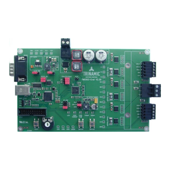
Page 5: Connectors
TMC603-EVAL Manual / Firmware V2.05 (Rev. 2.02 / 2013-APR-03) Connectors 3.1.2 Power RS232 Hall Motor UART JTAG Encoder Figure 3.2 Connectors of TMC603-EVAL TMC603-EVAL ONNECTORS OF Label Connector type Mating connector type RIA 330-02, 2 pol., 5mm pitch, shrouded RIA 349-2, screw type terminal block, header pluggable, centerline 5 mm / 0.197... -
Page 6: Power Connector
TMC603-EVAL Manual / Firmware V2.05 (Rev. 2.02 / 2013-APR-03) 3.1.2.1 Power Connector Label Direction Description Power (GND) Power supply and signal ground Power (Supply input) Supply voltage: +12… +48V DC Table 3.2 Power connector 3.1.2.2 Motor Connector Label Direction Description... -
Page 7: Switches And Potentiometer
TMC603-EVAL Manual / Firmware V2.05 (Rev. 2.02 / 2013-APR-03) 3.1.2.7 UART Connector Label Description Received data line Transmitted data line Signal and system ground Table 3.8 UART connector Switches and Potentiometer 3.1.3 Reset Potentiometer Switch1 Switch2 Figure 3.3 Switches and potentiometer... - Page 8 TMC603-EVAL Manual / Firmware V2.05 (Rev. 2.02 / 2013-APR-03) Jumper Label Description Enable/disable shunt ENRS Set this jumper together with the three jumpers Filter/Ext_Shunt. resistors for current There are two possibilities. measurement ENRS jumper together with three jumpers Filter/Ext_Shunt on pin position 2-3 (extern shunt). Now, the measurement of the motor current will be done with the shunt resistors on the board.
-
Page 9: Leds
TMC603-EVAL Manual / Firmware V2.05 (Rev. 2.02 / 2013-APR-03) LEDs 3.1.5 TMC603-EVAL S OF THE Status Label Description Error signal ERROR This red LED lights up upon an error is occurred by undervoltage of VLS or VCP as well as by short to ground of the power MOS half bridge. -
Page 10: Tmcl Overview
As with most TRINAMIC modules the software running on the STM32F ARM Cortex-M3 processor of the TMC603-EVAL consists of two parts, a boot loader and the firmware itself. Whereas the boot loader is installed during production and testing at TRINAMIC and remains – normally – untouched throughout the whole lifetime, the firmware can be updated by the user. -
Page 11: Getting Started With Tmcm-Bldc
TMC603-EVAL Manual / Firmware V2.05 (Rev. 2.02 / 2013-APR-03) Getting Started with TMCM-BLDC 4.1.1 The first step is to connect the module by clicking the Connect button. (Please refer to the specific hardware and firmware manuals of your module for further information about connecting cables etc. prior to this.) Proceed if the communication between module and PC is established. -
Page 12: Dialogues Of The Tmcm-Bldc
TMC603-EVAL Manual / Firmware V2.05 (Rev. 2.02 / 2013-APR-03) Dialogues of the TMCM-BLDC 4.1.2 4.1.2.1 Settings After connecting the module with the connect button you can choose the settings tab and fill in basic values: motor settings, encoder settings and commutation mode. All settings correspond to specific axis parameters of your module. - Page 13 TMC603-EVAL Manual / Firmware V2.05 (Rev. 2.02 / 2013-APR-03) 4.1.2.2 Torque Mode The torque mode tab offers the possibility to test different current settings and to evaluate the current control. A target current can be chosen. Further, the current PI control can be adjusted by choosing values for the P and I parameters.
- Page 14 TMC603-EVAL Manual / Firmware V2.05 (Rev. 2.02 / 2013-APR-03) 4.1.2.3 Velocity Mode The input area of the velocity mode tab has three parts: the velocity ramp control, the velocity control and the velocity PI control. In the middle of the input area is the velocity control, which is used to start the drive (in positive and negative direction) in velocity mode with a chosen speed [rpm] or stop it.
- Page 15 TMC603-EVAL Manual / Firmware V2.05 (Rev. 2.02 / 2013-APR-03) 4.1.2.4 Positioning Mode The input area of the positioning mode tab has three parts: the velocity ramp control, the positioning control, and the position p control. The velocity ramp control is the same as on the velocity mode tab. Maximum velocity and acceleration can be chosen and the velocity ramp can be enabled or disabled.
- Page 16 TMC603-EVAL Manual / Firmware V2.05 (Rev. 2.02 / 2013-APR-03) 4.1.2.5 TMCL The input area of the TMCL tab has the same structure as the appropriate window for TMCL direct mode of the TMCL-IDE. Command number, type, motor/bank and a chosen value can be set. By clicking the Send button the request will be sent to the module.
-
Page 17: File Menu Of Tmcm-Bldc
TMC603-EVAL Manual / Firmware V2.05 (Rev. 2.02 / 2013-APR-03) File Menu of TMCM-BLDC 4.1.3 The file menu of the TMCM-BLDC offers the possibility to import and to export settings. This is useful for transferring settings from one module to another. Settings can be exported (Export settings to *.ini) and afterwards imported to another module with the command Import settings from *.ini. -
Page 18: Tmcl-Ide
TMCL commands in direct mode. The TMCL-IDE is a PC application running under Windows 95/98/NT/2000/XP/Vista/Windows 7. For the TMC603-EVAL in particular the dialogue for configuring BLDC modules is important. Most other functions can be used, too. Please refer to the TMCL-IDE User Manual (www.trinamic.com) for detailed information about this. - Page 19 TMC603-EVAL Manual / Firmware V2.05 (Rev. 2.02 / 2013-APR-03) 4.2.1.1 Axis Parameters and Motion On the left side of the BLDC tool are two tabs, which can be chosen: Values TMCL The values tab offers a table with two columns:...
- Page 20 TMC603-EVAL Manual / Firmware V2.05 (Rev. 2.02 / 2013-APR-03) 4.2.1.2 Value Display While the TMCL BLDC tool is active the value display offers a smart visualization of all chosen adjustments. Changes of axis parameters and other commands will be shown immediately in graphics and table.
-
Page 21: Tmcl Command Overview
TMC603-EVAL Manual / Firmware V2.05 (Rev. 2.02 / 2013-APR-03) TMCL Command Overview In this section a short overview of the TMCL commands is given. Motion Commands 4.3.1 These commands control the motion of the motor. They are the most important commands and can be used in direct mode or in stand-alone mode. -
Page 22: Commands
TMC603-EVAL Manual / Firmware V2.05 (Rev. 2.02 / 2013-APR-03) Commands The module specific commands are explained in more detail on the following pages. They are listed according to their command number. ROR (rotate right) 4.4.1 The motor will be instructed to rotate with a specified velocity in right direction (increasing the position counter). -
Page 23: Rol (Rotate Left)
TMC603-EVAL Manual / Firmware V2.05 (Rev. 2.02 / 2013-APR-03) ROL (rotate left) 4.4.2 The motor will be instructed to rotate with a specified velocity (opposite direction compared to ROR, decreasing the position counter). Internal function: First, velocity mode is selected. Then, the velocity value is transferred to axis parameter #2 (target velocity). -
Page 24: Mst (Motor Stop)
TMC603-EVAL Manual / Firmware V2.05 (Rev. 2.02 / 2013-APR-03) MST (motor stop) 4.4.3 The motor will be instructed to stop. Internal function: The axis parameter target velocity is set to zero. Related commands: ROL, ROR, SAP, GAP Mnemonic: MST 0... -
Page 25: Mvp (Move To Position)
TMC603-EVAL Manual / Firmware V2.05 (Rev. 2.02 / 2013-APR-03) MVP (move to position) 4.4.4 The motor will be instructed to move to a specified relative or absolute position. It uses the acceleration/deceleration ramp and the positioning speed programmed into the unit. This command is non- blocking (like all commands). -
Page 26: Sap (Set Axis Parameter)
TMC603-EVAL Manual / Firmware V2.05 (Rev. 2.02 / 2013-APR-03) SAP (set axis parameter) 4.4.5 Most of the motion control parameters of the module can be specified by using the SAP command. The settings will be stored in SRAM and therefore are volatile. Thus, information will be lost after power off. -
Page 27: Gap (Get Axis Parameter)
TMC603-EVAL Manual / Firmware V2.05 (Rev. 2.02 / 2013-APR-03) GAP (get axis parameter) 4.4.6 Most parameters of the TMC603-EVAL can be adjusted individually. They can be read out using the GAP command. Related commands: SAP, STAP, and RSAP Mnemonic: GAP <parameter number>, 0... -
Page 28: Stap (Store Axis Parameter)
TMC603-EVAL Manual / Firmware V2.05 (Rev. 2.02 / 2013-APR-03) STAP (store axis parameter) 4.4.7 The STAP command stores an axis parameter previously set with a Set Axis Parameter command (SAP) permanently. Most parameters are automatically restored after power up. Internal function: An axis parameter value stored in SRAM will be transferred to EEPROM and loaded from EEPORM after next power up. -
Page 29: Rsap (Restore Axis Parameter)
TMC603-EVAL Manual / Firmware V2.05 (Rev. 2.02 / 2013-APR-03) RSAP (restore axis parameter) 4.4.8 For all configuration related axis parameters non-volatile memory locations are provided. By default, most parameters are automatically restored after power up. A single parameter that has been changed before can be reset by this instruction also. -
Page 30: Sgp (Set Global Parameter)
TMC603-EVAL Manual / Firmware V2.05 (Rev. 2.02 / 2013-APR-03) SGP (set global parameter) 4.4.9 Global parameters are related to the host interface, peripherals or other application specific variables. The different groups of these parameters are organized in banks to allow a larger total number for future products. -
Page 31: Ggp (Get Global Parameter)
TMC603-EVAL Manual / Firmware V2.05 (Rev. 2.02 / 2013-APR-03) GGP (get global parameter) 4.4.10 All global parameters can be read with this function. Related commands: SGP, STGP, RSGP Mnemonic: GGP <parameter number>, <bank number> Binary representation: COMMAND TYPE MOT/BANK VALUE <parameter number>... -
Page 32: Rsgp (Restore Global Parameter)
TMC603-EVAL Manual / Firmware V2.05 (Rev. 2.02 / 2013-APR-03) RSGP (restore global parameter) 4.4.12 This instruction copies a value from the configuration EEPROM to its RAM location and so recovers the permanently stored value of a RAM-located parameter. Most parameters are automatically restored after power up. -
Page 33: Sio (Set Output) And Gio (Get Input / Output)
SIO (set output) and GIO (get input / output) 4.4.13 The TMC603-EVAL provides two commands for dealing with inputs and outputs: SIO sets the status of the general digital output either to low (0) or to high (1). With GIO the status of the two available general purpose inputs of the module can be read out. The command reads out a digital or analogue input port. - Page 34 TMC603-EVAL Manual / Firmware V2.05 (Rev. 2.02 / 2013-APR-03) Mnemonic: GIO <port number>, <bank number> Binary representation: INSTRUCTION NO. TYPE MOT/BANK VALUE <port number> <bank number> don’t care Reply in direct mode: STATUS VALUE 100 – OK <status of the port>...
-
Page 35: Customer Specific Tmcl Command Extension (Uf0
The user definable functions UF0… UF7 are predefined functions without topic for user specific purposes. A user function UF command uses three parameters. Internal function: Call user specific functions implemented in C by TRINAMIC. Related commands: none Mnemonic: UF0… UF7 <parameter number>... -
Page 36: Axis Parameter Overview (Sap, Gap, Stap, Rsap)
TMC603-EVAL Manual / Firmware V2.05 (Rev. 2.02 / 2013-APR-03) Axis Parameter Overview (SAP, GAP, STAP, RSAP) The following section describes all axis parameters that can be used with the SAP, GAP, STAP and RSAP commands. EANING OF THE LETTERS IN COLUMN... - Page 37 TMC603-EVAL Manual / Firmware V2.05 (Rev. 2.02 / 2013-APR-03) Number Axis Parameter Description Range [Unit] Access BLDC 1: restart the timer and initialize encoder. (ignored) re-initialization PID regulation Delay of the position and velocity regulator 0… +10 loop delay [ms] Current Delay of the current regulator.
- Page 38 TMC603-EVAL Manual / Firmware V2.05 (Rev. 2.02 / 2013-APR-03) Number Axis Parameter Description Range [Unit] Access Encoder clear 1: set position counter to zero only once set NULL 0: always at an N channel event Activate stop Bit 0 Left stop switch When this bit is set 0…...
- Page 39 TMC603-EVAL Manual / Firmware V2.05 (Rev. 2.02 / 2013-APR-03) Number Axis Parameter Description Range [Unit] Access P parameter for P parameter of velocity PID regulator. 0… 65535 velocity PID I parameter for I parameter of velocity PID regulator. 0… 65535...
-
Page 40: Axis Parameters Sorted By Functionality
TMC603-EVAL Manual / Firmware V2.05 (Rev. 2.02 / 2013-APR-03) Axis Parameters Sorted by Functionality The following section describes all axis parameters that can be used with the SAP, GAP, STAP, RSAP and AAP commands. EANING OF THE LETTERS IN COLUMN... - Page 41 TMC603-EVAL Manual / Firmware V2.05 (Rev. 2.02 / 2013-APR-03) Number Axis Parameter Description Range [Unit] Access Actual Actual controlled angle value -32767… +32767 controlled angle Sine Velocity during initialization in init sine mode 2. -200000… +200000 initialization Refer to axis parameter 249, too.
- Page 42 TMC603-EVAL Manual / Firmware V2.05 (Rev. 2.02 / 2013-APR-03) Number Axis Parameter Description Range [Unit] Access PID regulation Delay of the position and velocity 0… +10 loop delay [ms] P parameter for P parameter of velocity PID regulator. 0… +10 velocity PID [50µs]...
- Page 43 TMC603-EVAL Manual / Firmware V2.05 (Rev. 2.02 / 2013-APR-03) Number Axis Parameter Description Range [Unit] Access Activate stop Bit 0 Left stop switch When this bit is set 0… 3 enable the motor will be switch stopped moving in negative...
- Page 44 TMC603-EVAL Manual / Firmware V2.05 (Rev. 2.02 / 2013-APR-03) Number Axis Parameter Description Range [Unit] Access Error/Status Bit 0: Overcurrent flag. This flag is set if max. 0…+4294967295 flags current limit is exceeded. Bit 1: Undervoltage flag. This flag is set if supply voltage is too low for motor operation.
-
Page 45: Global Parameter Overview (Sgp, Ggp, Stgp, Rsgp)
TMC603-EVAL Manual / Firmware V2.05 (Rev. 2.02 / 2013-APR-03) Global Parameter Overview (SGP, GGP, STGP, RSGP) The following section describes all global parameters that can be used with the SGP, GGP, STGP and RSGP commands. WO BANKS ARE USED FOR GLOBAL PARAMETERS... -
Page 46: Bank 2
TMC603-EVAL Manual / Firmware V2.05 (Rev. 2.02 / 2013-APR-03) Number Global Description Range Access parameter TMCL code Protect a TMCL program against disassembling or 0, 1, 2, 3 protection overwriting. 0 – no protection 1 – protection against disassembling 2 – protection against overwriting 3 –... -
Page 47: Motor Regulation
Motor Regulation Structure of the Cascaded Motor Regulation Modes The TMC603-EVAL supports a current, velocity, and position PID regulation mode for motor control in different application areas. These regulation modes are cascaded as shown in figure 7.1. The individual modes are explained in the following sections. -
Page 48: Current Regulation
TMC603-EVAL Manual / Firmware V2.05 (Rev. 2.02 / 2013-APR-03) Current Regulation The current regulation mode uses a PID regulator to adjust a desired motor current. This target current can be set by axis parameter 155. The maximal target current is limited by axis parameter 6. -
Page 49: Velocity Regulation
TMC603-EVAL Manual / Firmware V2.05 (Rev. 2.02 / 2013-APR-03) For all tests set the motor current limitation to a realistic value, so that your power supply does not become overloaded during acceleration phases. If your power supply reaches current limitation, the unit may reset or undetermined regulation results may occur. -
Page 50: Velocity Ramp Generator
PID regulator. Position Regulation Based on current and velocity regulators the TMC603-EVAL supports a positioning mode based on encoder or hall sensor position. During positioning the velocity ramp generator can be activated to enable motor positioning with controlled acceleration or it can be disabled to support motor positioning with max allowed speed. - Page 51 TMC603-EVAL Manual / Firmware V2.05 (Rev. 2.02 / 2013-APR-03) Switch on the velocity ramp generator. Based on the max. positioning velocity (axis parameter 4) and the acceleration value (axis parameter 11) the ramp generator automatically calculates the slow down point, i.e. the point at which the velocity has to be reduced in order to stop at the desired target position.
-
Page 52: Temperature Calculation
TMC603-EVAL Manual / Firmware V2.05 (Rev. 2.02 / 2013-APR-03) Temperature Calculation Axis parameter 152 delivers the actual ADC value of the motor driver. This ADC value can be converted to a temperature in °C as follows: Example 1: Example 2:... -
Page 53: 10 Life Support Policy
TMC603-EVAL Manual / Firmware V2.05 (Rev. 2.02 / 2013-APR-03) 10 Life Support Policy TRINAMIC Motion Control GmbH & Co. KG does not authorize or warrant any of its products for use in life support systems, without the specific written consent of TRINAMIC Motion Control GmbH &... -
Page 54: 11 Revision History
TMC603-EVAL Manual / Firmware V2.05 (Rev. 2.02 / 2013-APR-03) 11 Revision History Firmware Revision 11.1 Version Date Author Description 2.00 2012-JUL-10 New FOC firmware 2.02 2012-DEC-14 - Axis parameter 209 deleted. - Axis parameter 241 (sine initialization speed) added. - Axis parameter 31 (BLDC re-initialization) added.
Need help?
Do you have a question about the TMC603-EVAL and is the answer not in the manual?
Questions and answers