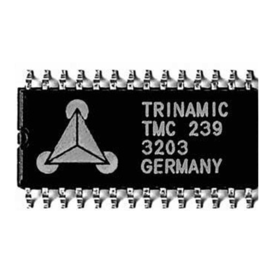
Summary of Contents for Trinamic TMC236
- Page 1 TMC236 and TMC239 Evaluation Kit Manual Version: 1.02 Date: January 24 , 2003 Deelbögenkamp 4c, D - 22 297 Hamburg, Germany Phone +49-40-51 48 06 - 0, FAX: +49-40-51 48 06 - 60 http://www.trinamic.com...
- Page 2 TMC236 / TMC239 Evaluation Kit Version Version Date Author Comment 1.00 12-17-2002 OK Describes Version 1.0 of the evaluation board 1.01 16-01-2003 OK Description of R-VT jumper and TSlope potentiometer added 1.02 24-01-2003 OK Maximum coil current values changed Contents Introduction................................
- Page 3 TMC236 / TMC239 Evaluation Kit 1 Introduction The TMC236 evaluation kit and the TMC239 evaluation kit make it possible to evaluate the features of the TMC236 and TMC239 stepper motor drivers. An evaluation kit contains the following things: • An evaluation board equipped with either a TMC236 or a TMC239 stepper motor driver an an AT90S2313 microcontroller.
- Page 4 Always turn off the power supply before a motor is being connected or disconnected, as otherwise the motor driver may be destroyed! Power Supply Connector RS232 Figure 2.1: The TMC236/TMC239 evaluation board Deelbögenkamp 4c, D - 22 297 Hamburg, Germany Phone +49-40-51 48 06 - 0, FAX: +49-40-51 48 06 - 60...
- Page 5 SPI Jumpers (J201): These four jumpers have to be closed for normal operation. When they are open, the SPI lines of the TMC236/TMC239 chip are separated from the microcontroller so that the external SPI or analogue input can be used to control the motor driver chip.
- Page 6 Please see the TMC236 or TMC239 data sheet for details. 2.3 LEDs on the board The board is equipped with LEDs that show the error flags of the TMC236 or TMC239 stepper motor driver. Their meanings are as follows: •...
- Page 7 In the “Error Bits” section the error flags sent back by the TMC236 are shown. Please see the TMC236 data sheet for an explanation of the error bits. The power supply voltage of the TMC236 evaluation board is too low if the “Open load”...


Need help?
Do you have a question about the TMC236 and is the answer not in the manual?
Questions and answers