Table of Contents
Advertisement
Quick Links
EVALUATION FOR ICs
Firmware Version V1.00
TMC5031-EVAL EVALUATION BOARD MANUAL
+
+
U
F
:
NIQUE
EATURES
TRINAMIC Motion Control GmbH & Co. KG
Hamburg, Germany
EVALUATION BOARD
TMC5031-EVAL
+
Evaluation Board for TMC5031
Motor Controller / Driver for
Two Phase Stepper Motors
Up to 2x 0.7A RMS/ +5.5V... 16V DC
USB, RS232, and SPI
2x Ref. Switch Input per Axis
+
Advertisement
Table of Contents

Related Manuals for Trinamic TMC5031-EVAL


Summary of Contents for Trinamic TMC5031-EVAL
- Page 1 Evaluation Board for TMC5031 Motor Controller / Driver for Two Phase Stepper Motors Up to 2x 0.7A RMS/ +5.5V… 16V DC USB, RS232, and SPI 2x Ref. Switch Input per Axis NIQUE EATURES TRINAMIC Motion Control GmbH & Co. KG Hamburg, Germany...
-
Page 2: Table Of Contents
TMC5031-EVAL Manual / Firmware V1.00 (Rev. 1.01 / 2013-MAR-26) ABLE OF ONTENTS Features ................................... 3 Order Codes ................................... 4 Hardware ..................................5 Mechanical and Electrical Interfacing ......................5 3.1.1 Size of TM5031-EVAL and Mounting Holes .................... 5 3.1.2 Overview of Connectors ..........................6 3.1.3... -
Page 3: Features
TMC5031-EVAL Manual / Firmware V1.00 (Rev. 1.01 / 2013-MAR-26) Features The TMC5031 evaluation board is designed for evaluating all features of the TMC5031 controller/driver IC. The STM32F ARM Cortex-M3 microcontroller is used to control the TMC5031. The FLASH memory of the microcontroller contains a program which configures the controller/driver chip and controls the communication with the PC via the USB interface and the RS232 interface. -
Page 4: Order Codes
TMC5031-EVAL Manual / Firmware V1.00 (Rev. 1.01 / 2013-MAR-26) TRINAMIC NIQUE EATURES stallGuard2™ stallGuard2 is a high-precision sensorless load measurement using the back EMF on the coils. It can be used for stall detection as well as other uses at loads below those which stall the motor. -
Page 5: Hardware
TMC5031-EVAL Manual / Firmware V1.00 (Rev. 1.01 / 2013-MAR-26) Hardware Mechanical and Electrical Interfacing Size of TM5031-EVAL and Mounting Holes 3.1.1 The board dimensions are 85mm x 55mm. Maximum component height (above PCB level) without mating connectors is 13.5mm. There are four mounting holes suitable for M3 screws. -
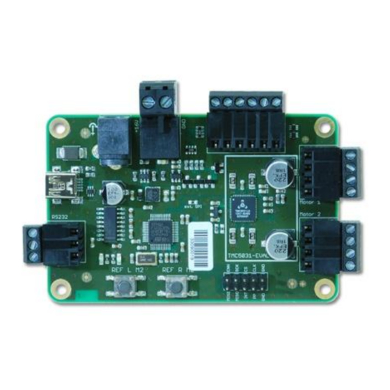
Page 6: Overview Of Connectors
TMC5031-EVAL Manual / Firmware V1.00 (Rev. 1.01 / 2013-MAR-26) Overview of Connectors 3.1.2 Power 2 Ref. Switches Power 1 Motor 1 RS232 Motor 2 SPI retrofit option Figure 3.2 Connectors of TMC5031-EVAL TMC5031-EVAL ONNECTORS OF Label (Key) Connector type Mating connector type... - Page 7 TMC5031-EVAL Manual / Firmware V1.00 (Rev. 1.01 / 2013-MAR-26) 3.1.2.2 RIA Power Connector (2) Label Description Power supply and signal ground +VCC Operational voltage: +5.5… 18V DC Table 3.3 Power connector 2 3.1.2.3 Motor Connector Axis 1 Label Description O1A1...
- Page 8 TMC5031-EVAL Manual / Firmware V1.00 (Rev. 1.01 / 2013-MAR-26) 3.1.2.8 SPI and Interrupts (Measurement Points and Retrofit Option) The SPI connector is not assembled, but can be retrofitted in case an external microcontroller should be used. Typically, these pins are used for measurements concerning SPI interface and interrupts (INT and PP).
-
Page 9: Push Buttons: Reference Switches Of Motor 2
Push Buttons: Reference Switches of Motor 2 3.1.3 The TMC5031-EVAL offers two push buttons for the reference switches of motor 2. As long as a button is pushed the related reference switch of motor 2 is active. Note that the ramp generator features dialogue of the evaluation software includes a switch mode tab which shows the status of switches. -
Page 10: Operational Ratings
TMC5031-EVAL Manual / Firmware V1.00 (Rev. 1.01 / 2013-MAR-26) 4 Operational Ratings The operational ratings shown below should be used as design values. The maximum power supply current depends on the used motors and the supply voltage. Do not exceed the maximum values during operation! Otherwise the driver will be damaged! -
Page 11: Getting Started - How To Connect The Board
TMC5031-EVAL Manual / Firmware V1.00 (Rev. 1.01 / 2013-MAR-26) 5 Getting Started – How to Connect the Board OU NEED RECAUTIONS - Evaluation board with stepper motor (e.g. - Do not mix up connections or short-circuit pins. QSH4218) - Avoid bounding I/O wires with motor wires. -
Page 12: Installing The Virtual Com Port For Usb Interface
Start the TMC50xx-EVAL.exe application with a double click. First, you will be asked, which module you like to connect. Choose the TMC5031-EVAL. Then, a hint will appear on the screen. If the module is not already connected, plug it, power it on, and click OK. -
Page 13: Evaluation Software
Optimized settings can be stored and exported. Starting the Evaluation Software Download the file TMC50xx-EVAL.exe from our website www.trinamic.com. The software is a PC application running under Windows XP, Vista, Windows 7, and Windows 8 (Windows 3.x is not supported). -
Page 14: Main Dialogues
TMC5031-EVAL Manual / Firmware V1.00 (Rev. 1.01 / 2013-MAR-26) Main Dialogues The evaluation software offers two main dialogues: the jog dialogue and the ramp generator dialogue on the next tab. Both dialogues offer separate data input fields for motor 1 and motor 2. -
Page 15: Basic Functions
TMC5031-EVAL Manual / Firmware V1.00 (Rev. 1.01 / 2013-MAR-26) Basic Functions Load / Save / Export Settings 6.3.1 Module settings can be loaded, saved, and exported. Click File on top menu and choose the desired action. Note that it is not possible to store settings permanently on the board. -
Page 16: Special Dialogues
TMC5031-EVAL Manual / Firmware V1.00 (Rev. 1.01 / 2013-MAR-26) Special Dialogues Click view on top menu or the specific fields on the left side of the main window to open up dialogues for special settings. Note that dcStep and encoder are not provided by the TMC5031. -
Page 17: Ramp Generator Features Dialogue
TMC5031-EVAL Manual / Firmware V1.00 (Rev. 1.01 / 2013-MAR-26) Ramp Generator Features Dialogue 6.4.2 This dialogue offers two tabs: the ramp status tab and the switch mode tab. These tabs correlate with each other. 6.4.2.1 Ramp Status Tab Ramp status flags can be polled continuously or on demand. - Page 18 TMC5031-EVAL Manual / Firmware V1.00 (Rev. 1.01 / 2013-MAR-26) 35, 0 55: RAMP_STAT – TMC5031 RAMP AND REFERENCE SWITCH STATUS REGISTER OF Name Comment event_stop_l 1: Signals an active stop left condition due to stop switch. This bit is ORed to the interrupt output signal.
- Page 19 TMC5031-EVAL Manual / Firmware V1.00 (Rev. 1.01 / 2013-MAR-26) 6.4.2.2 Switch Mode Tab With this tab, the SW_MODE register of the TMC5031 can be adjusted. Just tick the desired function to set it. If stallGuard stop is active and the motor stalls, deactivate the stallGuard event before going on with your tests.
- Page 20 TMC5031-EVAL Manual / Firmware V1.00 (Rev. 1.01 / 2013-MAR-26) 34, 0 54: SW_MODE – REFERENCE SWITCH AND STALL UARD EVENT CONFIGURATION REGISTER Name Comment pol_stop_r Sets the polarity of the right reference switch input (0=neg., 1=pos.) pol_stop_l Sets the polarity of the left reference switch input (0=neg., 1=pos.)
-
Page 21: Coolstep Dialogue
TMC5031-EVAL Manual / Firmware V1.00 (Rev. 1.01 / 2013-MAR-26) coolStep Dialogue 6.4.3 This dialogue is designed for adjusting coolStep. The coolStep current is shown in red and the stallGuard2 load in blue. The coolStep current value increases/decreases adequate to the measured load on the axis. -
Page 22: Chopper Configuration Dialogue
TMC5031-EVAL Manual / Firmware V1.00 (Rev. 1.01 / 2013-MAR-26) Chopper Configuration Dialogue 6.4.4 This dialogue has two tabs, one for motor 1 and the other one for motor 2. First, it is necessary to specify the chopper mode: spreadCycle or Classic. - Page 23 TMC5031-EVAL Manual / Firmware V1.00 (Rev. 1.01 / 2013-MAR-26) 6C, 0 7C: CHOPCONF – C HOPPER ONFIGURATION Name Function Comment vhighchm high velocity chopper This bit enables switching to chm=1 and fd=0, when mode VHIGH is exceeded. This way, a higher velocity can be achieved.
-
Page 24: Driver Status Information
TMC5031-EVAL Manual / Firmware V1.00 (Rev. 1.01 / 2013-MAR-26) Driver Status Information 6.4.5 This dialogue shows all driver error flags of the two motor drivers. The flags are related to the DRV_STATUS register. Blue marked flags are set. Figure 6.16 Motor driver error flags 6F, 0 7F: DRV_STATUS –... -
Page 25: Microstep Wave Dialogue
TMC5031-EVAL Manual / Firmware V1.00 (Rev. 1.01 / 2013-MAR-26) Microstep Wave Dialogue 6.4.6 The microstep wave dialogue has two tabs, one for motor 1 and the other one for motor 2. Each motor driver of the TMC5031 provides a programmable look-up table for storing the microstep current wave. - Page 26 TMC5031-EVAL Manual / Firmware V1.00 (Rev. 1.01 / 2013-MAR-26) XAMPLE TRIANGULAR MICROSTEP CURVE For a triangular curve, enter the following formula into the expression evaluator: Figure 6.18 Triangular curve XAMPLE MICROSTEP WAVE WITH LINEAR SCALED SINE WAVE AMPLITUDE For a wave with linear scaled sine wave amplitude the following formula may fit: Figure 6.19 Example for microstep wave with linear scaled sine wave amplitude...
- Page 27 TMC5031-EVAL Manual / Firmware V1.00 (Rev. 1.01 / 2013-MAR-26) 1: 0 60…0 6F, M 2: 0 70…0 OTOR DRIVER REGISTER SET OTOR OTOR Addr Register Description / bit names Range [Unit] MSLUT1[0] Each gives difference between 32x 0 or 1...
-
Page 28: Global Configuration Dialogue
TMC5031-EVAL Manual / Firmware V1.00 (Rev. 1.01 / 2013-MAR-26) Global Configuration Dialogue 6.4.7 This dialogue shows global status flags on the front tab and global settings on the rear tab. These flags and settings are related to the GENERAL CONFIGURATION REGISTERS of the TMC5031. Flags can be pulled continuously or on demand. -
Page 29: All Registers Dialogue
TMC5031-EVAL Manual / Firmware V1.00 (Rev. 1.01 / 2013-MAR-26) 00…0 ENERAL CONFIGURATION REGISTERS Addr Register Description / bit names Position comparison register for motor 1 position strobe. Activate poscmp_enable to get position pulse on output PP. 0x05 X_COMPARE XACTUAL = X_COMPARE: Output PP becomes high. -
Page 30: Life Support Policy
TMC5031-EVAL Manual / Firmware V1.00 (Rev. 1.01 / 2013-MAR-26) Life Support Policy TRINAMIC Motion Control GmbH & Co. KG does not authorize or warrant any of its products for use in life support systems, without the specific written consent of TRINAMIC Motion Control GmbH & Co. KG. -
Page 31: Revision History
TMC5031-EVAL Manual / Firmware V1.00 (Rev. 1.01 / 2013-MAR-26) Revision History Firmware Revision Version Date Author Description 2013-JAN-23 OK, MJ Initial version Table 8.1: Firmware revision Document Revision Version Date Author Description SD – Sonja Dwersteg 1.00 2013-FEB-22 Initial version...
Need help?
Do you have a question about the TMC5031-EVAL and is the answer not in the manual?
Questions and answers