Table of Contents
Advertisement
Quick Links
EVALUATION FOR ICs
Hardware Version V1.00
TMC5130-EVAL EVALUATION BOARD MANUAL
D
ESCRIPTION
The TMC5130-EVAL is designed for evaluating all features
of the TMC5130A-TA. The evaluation board is part of
TRINAMICs new user-friendly plug-in system for chip
evaluation.
Just
connect
STARTRAMPE, the associated base board. Therefore, use
the dedicated connector board, called ESELSBRÜCKE.
ESELSBRÜCKE offers test points for every connector pin.
TRINAMIC Motion Control GmbH & Co. KG
Hamburg, Germany
the
TMC5130-EVAL
with
EVALUATION BOARD
TMC5130-EVAL F
EATURES
Single wire interface to CPU
SPI interface to CPU
Step/Dir
interface
with
interpolation microPlyer™
Power connector
Motor connector
Retrofit option for encoder and
reference switch connectors
Multi-pin connector to base board
Multiple test points
TMCL-IDE 3.0 S
OFTWARE
TMCL-IDE 3.0 software allowing access
to all registers
Graphical view of position counter and
motor velocity
Additional tools for special features
TMC5130 M
C
AIN
HARACTERISTICS
2-phase bipolar stepper motors
Drive capability up to 2A coil current
Motion controller / sixPoint™ ramp
Voltage range 4.75... 46V DC
SPI & single wire UART
Dual ABN encoder interface
2x reference switch input
256 microsteps per full step
Full protection & diagnostics
dcStep™ load dependent speed control
stallGuard2™ high precision sensorless
motor load detection
coolStep™
load
dependent
control for energy savings up to 75%
stealthChop™
for
extremely
operation and smooth motion
spreadCycle™ high-precision chopper
for best current sine wave form and zero
crossing with additional chopSync2™
Integrated current sense option
Passive
breaking
and
mode
Small Size 9x9mm
TQFP48 package
2
microstep
current
quiet
freewheeling
Advertisement
Table of Contents

Related Manuals for Trinamic TMC5130-EVAL


Summary of Contents for Trinamic TMC5130-EVAL
- Page 1 Motion controller / sixPoint™ ramp Voltage range 4.75… 46V DC ESCRIPTION SPI & single wire UART The TMC5130-EVAL is designed for evaluating all features Dual ABN encoder interface of the TMC5130A-TA. The evaluation board is part of 2x reference switch input...
- Page 2 TMC5130-EVAL Manual / Firmware V1.00 (Rev. 0.92 / 2014-DEC-04) preliminary TRINAMIC NIQUE EATURES stallGuard2™ stallGuard2 is a high-precision sensorless load measurement using the back EMF on the coils. It can be used for stall detection as well as other uses at loads below those which stall the motor.
- Page 3 Order Codes The TMC5130-EVAL is a controller/driver board. It is part of the TRINAMICs evaluation board system. To have a complete operational system, the evaluation board needs to be connected to a baseboard with included microcontroller called STARTRAMPE. Therefore, use ESELSBRÜCKE, a special connector board with test points.
-
Page 4: Table Of Contents
TMC5130-EVAL Manual / Firmware V1.00 (Rev. 0.92 / 2014-DEC-04) preliminary Table of Contents Set-up and Features ..............................5 TMC5130-EVAL-KIT Dimensions..........................7 Dimensions ................................7 2.1.1 Dimensions of TM5130-EVAL and STARTRAMPE ................... 7 2.1.2 Dimensions of ESELSBRÜCKE ........................7 Evaluation Kit Connectors ............................8 TMC5130-EVAL Connectors and Test Points .................... -
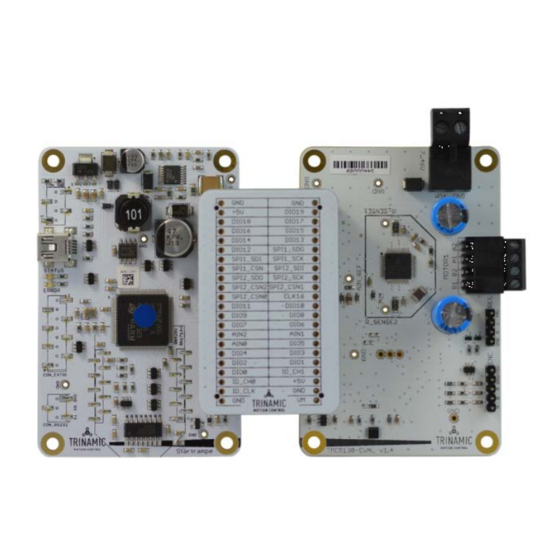
Page 5: Set-Up And Features
TMC5130-EVAL Manual / Firmware V1.00 (Rev. 0.92 / 2014-DEC-04) preliminary Set-up and Features The TMC5130-EVAL is part of an evaluation board system. Offering a very convenient handling for chip evaluation, TRINAMIC developed a plug-in system which consists of three parts: STARTRAMPE, ESELSBRÜCKE, and TMC5130-EVAL. - Page 6 TMC5130-EVAL Manual / Firmware V1.00 (Rev. 0.92 / 2014-DEC-04) preliminary TMC5130-EVAL F EATURES Integrated Motion Controller Linear six-point ramp generator. Motion profile calculation in real-time. On the fly alteration of motor parameters (e.g. position, velocity, acceleration). Integrated Motor Driver Up to 256 microsteps per full step.
-
Page 7: Tmc5130-Eval-Kit Dimensions
Board dimensions of both modules are 85mm x 55mm. There are four mounting holes suitable for M3 screws. TMC5130-EVAL maximum component height (above PCB level) without mating connectors: 12mm. STARTRAMPE maximum component height (above PCB level) without mating connectors: 11mm. -
Page 8: Evaluation Kit Connectors
TMC5130-EVAL Manual / Firmware V1.00 (Rev. 0.92 / 2014-DEC-04) preliminary Evaluation Kit Connectors 3.1 TMC5130-EVAL Connectors and Test Points Figure 3.1 Connectors of TMC5130-EVAL TMC5130-EVAL ONNECTORS OF Label (Key) Connector type Mating connector type RIA 349-2, screw type terminal block, RIA 330-02, 2 pol., 5mm pitch, shrouded... -
Page 9: Motor Connector
Left reference switch REF_R Right reference switch System and module ground Tabelle 3.1 Reference switch connector 3.1.5 Test Points (in addition to ESELSBRÜCKE) Apart from ESELSBRÜCKE the evaluation system provides test points on the TMC5130-EVAL. TMC5130-EVAL OINTS ON Label Description R_SENSE1... -
Page 10: Eselsbrücke: Spi Interface, I/Os, And Test Points
3.2 ESELSBRÜCKE: SPI Interface, I/Os, and Test Points The multi-pin connector ESELSBRÜCKE is used to connect STARTRAMPE and TMC5130-EVAL. Pin connections include the SPI interface, supply voltages, and IOs like driver enable (DRV_ENN), position compare (PP), interrupts (INT), and status flags. ESELSBRÜCKE offers test points for several measurements. -
Page 11: Startrampe: Connectors On The Base Board
TMC5130-EVAL Manual / Firmware V1.00 (Rev. 0.92 / 2014-DEC-04) preliminary Label Label Description ESELSBRÜCKE TMC5130-EVAL SPI2_CSN0 SPI2_CSN1 SPI0_SCN2 STARTRAMPE: SPI2 with three CS lines for driver module. Can SPI2_SCK be used as digital IOs. Not used with TMC5130-EVAL. SPI2_SDO SPI2_SDI... -
Page 12: Rs232 Connector (Not Soldered)
TMC5130-EVAL Manual / Firmware V1.00 (Rev. 0.92 / 2014-DEC-04) preliminary 3.3.2 RS232 Connector (not soldered) Label Description RS232 signal and system ground Received data line Transmitted data line Table 3.8 RS232 connector System Status LEDs STARTRAMPE has two LEDs. The green STATUS LED flashes constantly per default and indicates normal operation of the board. -
Page 13: Operational Ratings Of The Tmc5130-Eval-Kit
TMC5130-EVAL Manual / Firmware V1.00 (Rev. 0.92 / 2014-DEC-04) preliminary 5 Operational Ratings of the TMC5130-EVAL-KIT The operational ratings shown below should be used as design values. The maximum power supply current depends on the used motors and the supply voltage. -
Page 14: Getting Started
The TMC5130-EVAL-KIT supports both, USB self powered operation (when an external power is supplied via the power supply connector on the TMC5130-EVAL) and USB bus powered operation (only the USB interface is connected to the PC). On-board digital core logic will be powered via USB in case no other supply is connected. -
Page 15: Starting Up
TMC5130-EVAL Manual / Firmware V1.00 (Rev. 0.92 / 2014-DEC-04) preliminary 6.1 Starting up Download the TMCL-IDE 3.0 from www.trinamic.com and install it. Afterwards, the TMCL-IDE opens up automatically. Connect the USB interface. Now, the software guides you through the installation of a virtual COM port for the USB interface. -
Page 16: Checking The Status Of Startrampe And Tmc5130-Eval
TMC5130-EVAL Manual / Firmware V1.00 (Rev. 0.92 / 2014-DEC-04) preliminary Here, new values can be set for each chosen parameter. Here, connections Here is an overview of all are indicated and parameters. Choose one and all modes of necessary information appears on... -
Page 17: Velocity Mode
TMC5130-EVAL Manual / Firmware V1.00 (Rev. 0.92 / 2014-DEC-04) preliminary Note In order to achieve good settings it is necessary to work using the TMC5130 datasheet. The register browser of the TMCL-IDE offers helpful information about any parameter which is selected. But the list is alphabetically. -
Page 18: Positioning Mode
TMC5130-EVAL Manual / Firmware V1.00 (Rev. 0.92 / 2014-DEC-04) preliminary 6.3 Positioning Mode For moving the motor in positioning mode, set two ticks on the left side of the main window in order to open the positioning mode dialogue and the position graph. Thereafter choose settings for... -
Page 19: Direct Mode Dialogue
TMC5130-EVAL Manual / Firmware V1.00 (Rev. 0.92 / 2014-DEC-04) preliminary 6.4 Direct Mode Dialogue For driving the motor in direct mode, set a tick on the left side of the main window. Now, the direct mode dialogue window pops up. The direct mode is used to issue commands and create complete programs. -
Page 20: Coolstep And Stallguard2
TMC5130-EVAL Manual / Firmware V1.00 (Rev. 0.92 / 2014-DEC-04) preliminary 6.5 coolStep and stallGuard2 This dialogue can be used to set stallGuard2 and coolStep parameters and to read out actual motor current values as well as the stallGuard values. Choose a stallGuard threshold to use stallGuard2. With a tick at filter enable reading out the values gets more comfortable. -
Page 21: Life Support Policy
TMC5130-EVAL Manual / Firmware V1.00 (Rev. 0.92 / 2014-DEC-04) preliminary Life Support Policy TRINAMIC Motion Control GmbH & Co. KG does not authorize or warrant any of its products for use in life support systems, without the specific written consent of TRINAMIC Motion Control GmbH &... -
Page 22: Revision History
TMC5130-EVAL Manual / Firmware V1.00 (Rev. 0.92 / 2014-DEC-04) preliminary Revision History 8.1 Firmware Revision Version Date Author Description 2014-NOV-07 OK, MJ, TE TMCL-IDE 3.0 ßVersion Table 8.1 Firmware revision 8.2 Document Revision Version Date Author Description SD – Sonja Dwersteg 0.92...
Need help?
Do you have a question about the TMC5130-EVAL and is the answer not in the manual?
Questions and answers