
Subscribe to Our Youtube Channel
Related Manuals for Moxa Technologies MC-7270-DC-CP-T


Summary of Contents for Moxa Technologies MC-7270-DC-CP-T
- Page 1 MC-7270-DC-CP-T User’s Manual Edition 2.0, February 2017 www.moxa.com/product © 2017 Moxa Inc. All rights reserved.
- Page 2 MC-7270-DC-CP-T User’s Manual The software described in this manual is furnished under a license agreement and may be used only in accordance with the terms of that agreement. Copyright Notice © 2017 Moxa Inc. All rights reserved. Trademarks The MOXA logo is a registered trademark of Moxa Inc.
-
Page 3: Table Of Contents
Product Features ..........................1-2 Hardware Specifications ........................1-3 Hardware Block Diagram ........................1-4 Hardware Introduction ........................2-1 Appearance ............................2-2 MC-7270-DC-CP-T Front View ....................... 2-2 MC-7270-DC-CP-T Rear View ......................2-2 Dimensions ............................2-3 LED Indicators ............................ 2-3 Real Time Clock ..........................2-4 Hardware Connection Description ..................... -
Page 5: Introduction
Introduction In this chapter, we present specifications, discuss hardware installation, and how to configure the BIOS. The following topics are covered in this chapter: Overview Package Checklist Product Features Hardware Specifications Hardware Block Diagram... -
Page 6: Overview
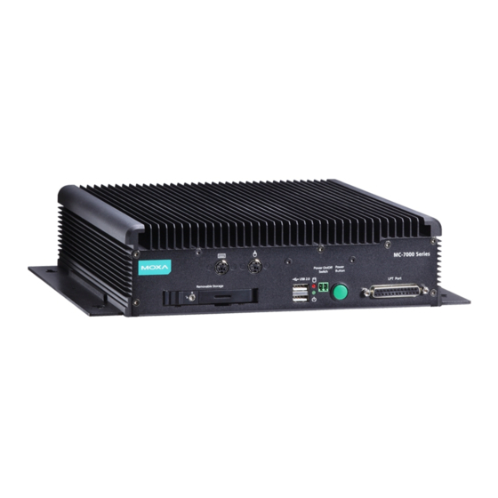
MC-7270-DC-CP-T Introduction Overview The MC-7270-DC-CP-T computer features the Intel® Core™ CPU processor and comes with 4 serial ports, 4 Gigabit Ethernet ports, and 6 USB hosts. The computer offers high performance and versatile peripherals for marine applications. Designed with the highest quality and durability in mind, the marine-grade MC-7270-DC-CP-T computer features a rugged chassis that can withstand 1g vibrations, providing a reliable platform that can be used even in harshest of environments. -
Page 7: Hardware Specifications
MC-7270-DC-CP-T Introduction Hardware Specifications Computer CPU: Intel® Core™ i7-3555LE, dual core 64-bit 2.5 GHz processor Supported OS: Windows 7, Windows XP SP3, Windows XP Embedded (must be installed by the user) System Chipset: Intel® QM77 Express Chipset System Memory: 16 GB capacity, with 4 GB pre-installed (2 slots total, with a 4 GB DDR3/DDR3L-1600 204... -
Page 8: Hardware Block Diagram
MC-7270-DC-CP-T Introduction Anti-Vibration: • 0.7 g @ DNV 2.4 (Class A), sine wave, 2-100 Hz, 1 Oct./min., 1.5 hr per axis • 1 g @ DNV 2.4, random wave, 3-100 Hz, 2.5 hr per axis • 2.1 g @ DNV 2.4 (Class C), sine wave, 2-50 Hz, 1 Oct./min., 1.5 hr per axis... -
Page 9: Hardware Introduction
Hardware Introduction The MC-7270-DC-CP-T computer is compact, well-designed, and built rugged enough for industrial applications. LED indicators help you monitor performance and identify trouble spots, multiple serial ports allow you to connect different devices for wireless operation, and the reliable and stable hardware platform lets you devote your attention to developing your applications. -
Page 10: Appearance
MC-7270-DC-CP-T Hardware Introduction Appearance MC-7270-DC-CP-T Front View MC-7270-DC-CP-T Rear View... -
Page 11: Dimensions
MC-7270-DC-CP-T Hardware Introduction Dimensions LED Indicators LED Name LED Color LED Function Green Power is on and functioning normally Power (on the front panel) Power is off or a power error exists Red (on) HDD/SSD is inserted and detected Storage... -
Page 12: Real Time Clock
MC-7270-DC-CP-T Hardware Introduction Real Time Clock The embedded computer’s real-time clock is powered by a lithium battery. We strongly recommend that you do NOT replace the lithium battery yourself. If the battery needs to be changed, contact the Moxa RMA service team at http://www.moxa.com/rma/about_rma.aspx. -
Page 13: Hardware Connection Description
Hardware Connection Description This chapter shows you how to connect the MC-7270-DC-CP-T to the network and to various devices. The following topics are covered in this chapter: Installing the MC-7270-DC-CP-T Wiring Requirements Connecting the Power Grounding the MC-7270-DC-CP-T ... -
Page 14: Installing The Mc-7270-Dc-Cp-T
Wall or Cabinet Mounting The MC-7270-DC-CP-T comes with two brackets pre-installed on both ends of the computer. Use two screws per side to attach the MC-7270-DC-CP-T to a wall or cabinet. We recommend that you use size M4 or larger screws. -
Page 15: Connecting The Power
Hardware Connection Description Connecting the Power The MC-7270-DC-CP-T model has a 24 VDC power input (with tolerance from 18 to 30 VDC) through the terminal block. If power is supplied properly, the Power LED will light up. For safety reasons, please use cables with the following specifications:... -
Page 16: Connecting To A Serial Device
Connecting to the USB Device The MC-7270-DC-CP-T comes with 2 USB 2.0 hosts on the front panel, and 4 USB 2.0 hosts on the rear panel. The hosts can be used for an external flash disk or hard drive for storing large amounts of data. You can also... -
Page 17: Connecting To A Vga Monitor
Connecting to a VGA Monitor The MC-7270-DC-CP-T comes with a D-Sub 15-pin female connector on the front panel to connect a VGA monitor. To ensure that the monitor image remains clear, be sure to tighten the monitor cable after connecting it to the MC-7270-DC-CP-T. -
Page 18: Connecting To A Speaker Or A Headphone
Installing the Removable SATA Storage Drive The MC-7270-DC-CP-T includes a removable storage device tray on the front panel. You need to install your own storage drive. Either a SATA hard disk or solid state drive may be installed, but only an SSD will ensure full anti-vibration compliance. -
Page 19: Installing The Internal Sata Storage Drive
Hardware Connection Description Installing the Internal SATA Storage Drive You can install a SATA storage drive in the internal SATA slot in the MC-7270-DC-CP-T. This allows you to expand the storage capacity of the MC-7270-DC-CP-T. Before you continue, make sure that you have the storage drive expansion kit that is included your MC-7270-DC-CP-T package. - Page 20 MC-7270-DC-CP-T Hardware Connection Description 8. Turn the storage drive so that the SATA connector is facing you. 9. Place the plastic plate over the storage drive. Make sure that the switch hole cutouts on the plastic plate align with the screw holes on the storage drive.
-
Page 21: Upgrading The Memory Module
MC-7270-DC-CP-T Hardware Connection Description Upgrading the Memory Module The MC-7270-DC-CP-T comes with 4 GB DDR3 SDRAMs pre-installed, and supports up to a maximum of 16 GB DDR3/DDR3L SDRAM. To upgrade the memory module, complete the following steps: 1. Remove the removable storage tray on the front panel. - Page 22 MC-7270-DC-CP-T Hardware Connection Description 4. When finished, remove the storage tray cover to expose the memory module. 5. There are two latches, one on either side of the memory module. Push the latches outward to release the memory module. The memory module automatically pops out. Gently remove the memory module.
-
Page 23: Bios Setup
BIOS Setup This chapter describes the BIOS settings of the MC-7270-DC-CP-T computer. The BIOS is a set of input/output control routines for peripherals. The BIOS is used to initialize basic peripherals and helps boot the operating system before the operating system is loaded. The BIOS setup allows the user to modify the system configurations of these basic input/output peripherals. -
Page 24: Entering The Bios Setup Utility
MC-7270-DC-CP-T BIOS Setup Entering the BIOS Setup Utility To enter the BIOS setup utility, press the “F2” key while the system is booting up. The main BIOS Setup screen will appear. Select SCU to enter the BIOS configuration. A basic description of each function key is listed at the bottom of the screen. Refer to these descriptions to learn how to scroll about the screen, how to select by pressing “Enter,”... -
Page 25: Main Information
MC-7270-DC-CP-T BIOS Setup Main Information The Main screen provides system information, including the model name, BIOS version, and CPU type. You can view basic system hardware information on this page. Advanced Settings Use the Advanced screen to configure advanced device settings (for example, boot settings). -
Page 26: Boot Configuration
MC-7270-DC-CP-T BIOS Setup Boot Configuration This screen allows you to configure the Numlock state. Option: On (default), Off. Peripherals Configuration This item allows you to configure the parallel port. -
Page 27: Hdc Configuration: Storage Device Bios Settings
MC-7270-DC-CP-T BIOS Setup Parallel Port This item allows you to configure the parallel port. Options: 378/IRQ7 (default), Disabled Mode This setting allows you to configure the mode for the parallel port. Options: SPP (default), EPP, ECP, EPP+ECP HDC Configuration: Storage Device BIOS Settings The HDC configuration section is where the BIOS settings for all storage devices are configured. - Page 28 MC-7270-DC-CP-T BIOS Setup For normal SATA functionality, select AHCI. When this option is selected, AHCI SALP (Support Aggressive Link Power Management) may be enabled. The four SATA interfaces (0–3) will be highlighted; only the first two SATA ports are enabled by default, with port 0 enabling the removable drive tray on the front panel, and port 1 enabling the drive expansion slot accessed through the bottom panel.
- Page 29 MC-7270-DC-CP-T BIOS Setup The Software Feature Mask Configuration will appear as below. RAID 0 is a simple striping of information across two drives. It offers marginal improvements in access times for substantial sacrifices in system reliability. RAID 1 offers full data redundancy across two drives, providing significant improvements in data security and system reliability.
-
Page 30: Video Configuration
MC-7270-DC-CP-T BIOS Setup Serial ATA Port 0 to 3 This setting allows you to configure the type of the storage drive installed in the computer. Only the first two ports (ports 0 and 1) will be available for use: port 0 represents the removable drive tray on the front panel, while port 1 represents the drive expansion slot accessed from the bottom panel. -
Page 31: Chipset Configuration
MC-7270-DC-CP-T BIOS Setup IGD—Boot Type This item allows you to select the video device that will be activated during POST. Options: VBIOS Default (default), VGA, DVI-D1, DVI-D2 Chipset Configuration This item allows you to configure the chipset settings. VT-d This item allows you to enable/disable the VT-d function. -
Page 32: Hardware Monitor
MC-7270-DC-CP-T BIOS Setup Hardware Monitor This item allows you to view stats like CPU and system temperature, voltage levels, and other chipset information. Security Settings The section allows users to configure security settings with supervisor password and user password. 4-10... -
Page 33: Set Supervisor Password
MC-7270-DC-CP-T BIOS Setup Set Supervisor Password This item allows you set the supervisor password. Select and then enter the password, and then confirm the password again. To cancel the password, enter Set Supervisor Password item, and then enter the old password. Leave the new password fields blank, and then press enter. -
Page 34: Boot Settings
MC-7270-DC-CP-T BIOS Setup Boot Settings The section allows users to configure boot settings. Boot Type This function sets the system OS to boot from EFI or Legacy. Options: Dual Boot Type (Default), Legacy Boot Type, UEFI Boot Type PXE Boot to LAN This item allows you to enable/disable the PXE boot to LAN function. -
Page 35: Boot Delay Time
MC-7270-DC-CP-T BIOS Setup Boot Delay Time Sets the BIOS boot delay time for information checking. Options: 0 sec (default), 3 sec, 5 sec, 10 sec Legacy Normal Boot Menu This item allows you to configure the boot menu. Options: Normal (default), Advance Boot Type Order This item allows you to select the boot order. -
Page 36: Exit Saving Changes
MC-7270-DC-CP-T BIOS Setup Exit Saving Changes This item allows you to exit the BIOS environment and save the values you have just configured. Options: Yes (default), No Save Change Without Exit This item allows you to save changes without exiting the BIOS environment. - Page 37 (xx refers to version numbers). 2. Copy the file to the Bootable USB Disk. Step 3: Run the upgrade program on the MC-7270-DC-CP-T Computer 1. Reboot the computer, and press F2 during the startup process and select the Boot Manager 2.
- Page 38 MC-7270-DC-CP-T BIOS Setup 4. Run the upgrade program by typing MC7270S03.exe. The upgrade filename may vary depending on the version. C:\MC_7270>MC7270S03.exe 5. The upgrade program will run automatically. Please wait patiently until the procedure finishes. 6. When the upgrade is complete, the computer will automatically reboot. You may check the BIOS version on the Main page of the BIOS Setup.
-
Page 39: Regulatory Approval Statement
Regulatory Approval Statement This device complies with part 15 of the FCC Rules. Operation is subject to the following two conditions: (1) This device may not cause harmful interference, and (2) this device must accept any interference received, including interference that may cause undesired operation. -
Page 40: Adjusting The Audio Mixer Function
Adjusting the Audio Mixer Function This chapter describes how to adjust the audio settings for the MC-7270-DC-CP-T’s Mixer function under the Windows XP and Windows XP Embedded operating systems. Since the Mixer function is enabled by default, you need modify the default settings of the Realtek audio device so that sounds picked up from the microphone will not be recorded. - Page 41 MC-7270-DC-CP-T Adjusting the Audio Mixer Function 4. Uncheck the Select checkbox under Stereo Mix and check the Select checkbox under Mix Volume to complete the configuration.
-
Page 42: Configuring The Serial Ports
Configuring the Serial Ports This chapter shows how to configure the 3-mode serial ports, COM3 and COM4, using the application on the product CD. The path to the application is <Software DVD>\MC-7270-DC-CP-T\utility\mxsif How to Install the Application 1. Double click the utility Mxsp_MC-7200_1.0_x64_Setup. When the following setup message appears,... - Page 43 MC-7270-DC-CP-T Configuring the Serial Ports 2. Select Install for anyone using this computer or Install just for me and then click Next > to proceed. 3. Specify which folder on this computer you would like the application to be installed in, and then click...
-
Page 44: How To Use The "Mxserialinterface" Utility
MC-7270-DC-CP-T Configuring the Serial Ports 4. Click Finish to complete the installation process. How to Use the “mxSerialInterface” Utility 1. Double click the mxSerialInterface icon. 2. The application UI will appear as shown below. 3. Select COM3 or COM4 from the Port drop-down menu. - Page 45 MC-7270-DC-CP-T Configuring the Serial Ports 4. Select “RS232”, “RS485 2 wires”, or “RS422/RS485 4 wires” from the Mode drop-down menu. 5. For example, if you select “COM4” and “RS232” and then click OK, you can use COM4 as an RS-232 serial...
Need help?
Do you have a question about the MC-7270-DC-CP-T and is the answer not in the manual?
Questions and answers