Sign In
Upload
Download
Table of Contents
Contents
Add to my manuals
Delete from my manuals
Share
URL of this page:
HTML Link:
Bookmark this page
Add
Manual will be automatically added to "My Manuals"
Print this page
×
Bookmark added
×
Added to my manuals
Manuals
Brands
Chauvin Arnoux Manuals
Measuring Instruments
C.A 6521
User manual
Chauvin Arnoux C.A 6521 User Manual
Megohmmeter
Hide thumbs
1
2
Table Of Contents
3
4
5
6
7
8
9
10
11
12
13
14
15
16
17
18
19
20
21
page
of
21
Go
/
21
Contents
Table of Contents
Bookmarks
Table of Contents
Table of Contents
1 Presentation
General Presentation
The Megohmmeter
Accessories
2 Description
Unit
6521
6523
6525
Display
Symbols
Bargraph
Digital Display
Control Keyboard
Yellow Key
ALARM Key (C.A 6523 and C.A 6525)
Key (C.A 6523 and C.A 6525)
Key (C.A 6523 and C.A 6525)
TIMER Key (C.A 6525)
Measurement Functions
Insulation
Safety Checking
Insulation Measurement
Continuity
Resistance (C.A 6523 and C.A 6525)
Special Functions
Start/Stop
Automatic Shutdown
Deactivation of Automatic Shutdown Function
(C.A 6523 and C.A 6525)
Power Supply Autotest
Buzzer
The Different Audible Signals
Deactivation of the Buzzer
Alarm Thresholds (C.A 6523 and C.A 6525)
Programming of the Alarm Thresholds
Activation/Deactivation of the Alarm Thresholds
Triggering of the Alarm
Compensation of Measuring Leads
(C.A 6523 and C.A 6525)
Timer (C.A 6525)
5 Use
Insulation Testing
Continuity Measurements
Resistance Measurements (C.A 6523 and C.A 6525)
6 Characteristics
Reference Conditions
Characteristics Per Function
Voltage
Insulation
Continuity
Resistance (C.A 6523 and C.A 6525)
Timer (C.A 6525)
Power Supply
Climatic Conditions
Variations in Nominal Field of Use
Limits
Construction Specifications
Compliance with International Norms
Electromagnetic Compatibility : EC Compliance
Mechanical Protection
Maintenance
Upkeep
Replacing the Batteries
Replacing the Fuse
Cleaning
Storage
Calibration
Maintenance
Warranty
To Order
Advertisement
Quick Links
1
General Presentation
2
6525
3
6523
4
Insulation
5
Insulation Testing
Download this manual
MEGOHMMETRES
MEGOHMMETERS
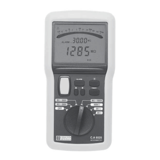
MEGOHMMETER
MEGAOHMMETRI
MEGAÓHMETRO
F R A N Ç A I S
E N G L I S H
D E U T S C H
I T A L I A N O
E S P A N O L
Notice de fonctionnement
User's manual
Bedienungsanleitung
Libretto d'Istruzioni
Manual de Instrucciones
1
C.A 6521
C.A 6523
C.A 6525
Table of
Contents
Previous
Page
Next
Page
1
2
3
4
5
Advertisement
Table of Contents
Need help?
Do you have a question about the C.A 6521 and is the answer not in the manual?
Ask a question
Questions and answers
Related Manuals for Chauvin Arnoux C.A 6521
Measuring Instruments Chauvin Arnoux C.A 6522 User Manual
Megohmmeters (38 pages)
Measuring Instruments Chauvin Arnoux CA 6522 Quick Start Manual
Megohmmeters (12 pages)
Measuring Instruments Chauvin Arnoux C.A 6524 User Manual
Megohmmeters (38 pages)
Measuring Instruments Chauvin Arnoux C.A 6523 User Manual
Megohmmeter (21 pages)
Measuring Instruments Chauvin Arnoux C.A 6525 User Manual
Megohmmeter (21 pages)
Measuring Instruments Chauvin Arnoux C.A 6528 User Manual
Megohmmeter (34 pages)
Measuring Instruments Chauvin Arnoux C.A 6528 Quick Start Manual
Megohmmeter (12 pages)
Measuring Instruments Chauvin Arnoux CA 6549 User Manual
Megohmmeter (132 pages)
Measuring Instruments Chauvin Arnoux CA6547 User Manual
Megohmmeter (24 pages)
Measuring Instruments Chauvin Arnoux C.A 6545 User Manual
Megohmmeters (32 pages)
Measuring Instruments Chauvin Arnoux C.A 6545 User Manual
Megohmmeters (162 pages)
Measuring Instruments Chauvin Arnoux C.A 6545 User Manual
Megohmmeters (32 pages)
Measuring Instruments Chauvin Arnoux C.A 6531 User Manual
Megohmmeters (22 pages)
Measuring Instruments Chauvin Arnoux C.A 6533 User Manual
Megohmmeters (22 pages)
Measuring Instruments Chauvin Arnoux C.A. 6505 User Manual
Megohmmeter (24 pages)
Measuring Instruments Chauvin Arnoux C.A 6505 User Manual
Megohmmeter (72 pages)
This manual is also suitable for:
C.a 6523
C.a 6525
Table of Contents
Print
Rename the bookmark
Delete bookmark?
Delete from my manuals?
Login
Sign In
OR
Sign in with Facebook
Sign in with Google
Upload manual
Upload from disk
Upload from URL


Need help?
Do you have a question about the C.A 6521 and is the answer not in the manual?
Questions and answers