
Related Manuals for JUMO cTRON 04


Summary of Contents for JUMO cTRON 04
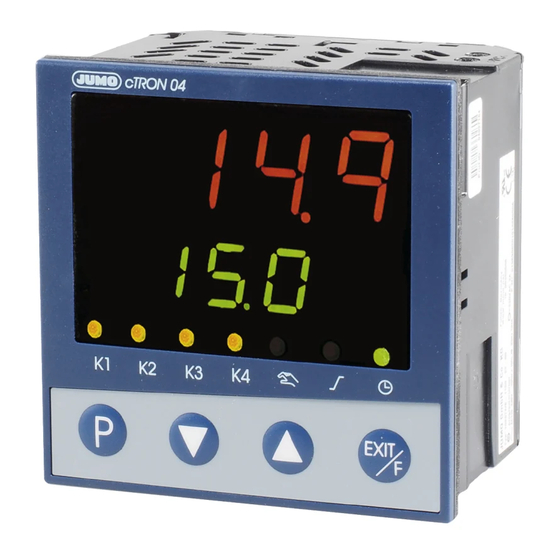
- Page 1 JUMO cTRON 04/08/16 Compact controller with timer and ramp function 702071 702072 702074 B 70.2070.2.0 Interface Description Modbus 2008-08-11/00492538...
-
Page 3: Table Of Contents
Contents Introduction Preface ......................5 Typographical conventions ............... 5 Protocol description Master-Slave principle ................7 Transmission mode (RTU) ................. 7 Device address ................... 8 Timing of the communication ..............8 Structure of the data blocks ..............11 Function codes ..................12 2.6.1 Read n words ..................... - Page 4 Contents...
-
Page 5: Introduction
1 Introduction 1.1 Preface This operating manual is addressed to the system manufacturer with adequate technical background and PC related knowledge. Please read this operating manual prior to commissioning the device. Keep the manual in a place accessible to all users at all times. Your comments are appreciated and may assist us in improving this manual. - Page 6 1 Introduction...
-
Page 7: Protocol Description
2 Protocol description 2.1 Master-Slave principle Communication between a master (e.g. PC) and a slave (e.g. measuring and control system) using Modbus takes place according to the master-slave principle, in the form of data request/instruction - response. Master Slave 1 Slave 2 Slave n The master controls the data exchange, the slaves only have a response... -
Page 8: Device Address
2 Protocol description 2.3 Device address The device address of the slave can be set between 0 and 254. Device address 0 is reserved. A maximum of 31 slaves can be addressed via the RS485 interface. There are two different forms of data exchange: Query Data request/instruction by the master to a slave via the corresponding device address. - Page 9 2 Protocol description Timing Data request from master transmission time = n characters * 1000 * x bit/baud rate Marker for end of data request 3 characters * 1000 * x bit/baud rate Processing of data request by the slave (≤ 250ms) Response of the slave transmission time = n characters * 1000 * x bit/baud rate Marker for end of response...
- Page 10 2 Protocol description Timing A data request runs according to the following timing scheme: scheme Data request Data request Master Response Slave End marker = 3 characters (time depending on the baud rate) This time depends on the internal processing. The maximum processing time is 250 ms.
-
Page 11: Structure Of The Data Blocks
2 Protocol description Structure of the data blocks All data blocks have the same structure: Data structure Slave Function Data field Checksum address code CRC16 1 byte 1 byte x byte 2 bytes Each data block contains four fields: Slave address device address of a specific slave Function code function selection (read, write words) -
Page 12: Function Codes
2 Protocol description Function codes The functions described in the following are available for the readout of measured values, device and process data as well as to write specific data. Function- Function Function Limitation overview number 0x03 or 0x04 Read n words max. -
Page 13: Write One Word
2 Protocol description 2.6.2 Write one word For the Write Word function, the data blocks for instruction and response are identical. Instruction Slave Function Word address Word value Checksum address 0x06 CRC16 1 byte 1 byte 2 byte 2 bytes 2 byte Response Slave... -
Page 14: Write N Words
2 Protocol description 2.6.3 Write n words This function is used to write n (n ≤ 32) words starting from a specific address. Instruction Slave Function Address Number Number Word ChecksumC address 0x10 first word of words value(s) RC16 (max. 32) words 1 byte 1 byte... -
Page 15: Transmission Format (Integer, Float And Text Values)
2 Protocol description Transmission format (integer, float and text values) Integer values Integer values are transmitted via the Modbus in the following format: The high byte first, followed by the low byte. Example Request of the integer value of address 0x0021, if value "4" (word value 0x0004) is written under this address. - Page 16 2 Protocol description Character Character strings (texts) are transmitted in the ASCII format. strings To mark the end, the last character to be transmitted can be a "\0" (texts) (ASCII code 0x00). Characters after this mark are without significance. The address tables show the max. possible number of characters in a data type, e.g.
-
Page 17: Checksum (Crc16)
2 Protocol description Checksum (CRC16) The checksum (CRC16) serves to recognize transmission errors. If an error is identified during evaluation, the device concerned does not respond. Calculation CRC = 0xFFFF scheme CRC = CRC XOR ByteOfMessage For (1 to 8) CRC = SHR(CRC) if (flag shifted right = 1) then... -
Page 18: Error Processing
2 Protocol description Error processing Error codes The following error codes exist: invalid function invalid parameter address or too many words are to be read or written write access to parameter denied Response in Slave Function Error code Checksum address XX OR 80h CRC16 event of an... -
Page 19: Rs485 Interface
3 RS485 interface 3.1 Connection diagram The devices of this controller series can be ordered with an RS485 interface as an option. Please refer to the type sheet 70.2070 or the operating manual B 70.2070.0 (type explanation) for the order specifications. -
Page 20: Configuration
3 RS485 interface 3.2 Configuration The following table shows the possible Modbus interface settings to be carried out in the configuration level (ConF IntF) and/or in the setup program. For more detailed information about configuration, please refer to operating manual B 70.2070.0. Symbol Value/ Description... -
Page 21: Modbus Addresses
4 Modbus addresses Data type, The following tables contain specifications of all process and device data including their addresses, data type and type of access. type of access Meaning: Read only access Write only access Read/write access Integer (8 or 16 bit) Bit x Bit No. - Page 22 4 Modbus addresses Address Data type/ Access Signal designation bit number 0x0023 Binary inputs 1 and 2 (Switching states 0 = open / 1 = closed) Bit 0 Input 1 (= 0x0001) Bit 1 Input 2 (= 0x0002) 0x0024 Limit comparators 1...2 Bit 0 Limit comparator 1 (= 0x0001) Bit 1...
-
Page 23: Set Point Values
4 Modbus addresses 4.2 Set point values Address Data type/ Access Signal designation bit number 0x3100 FLOAT Set point value W1 0x3102 FLOAT Set point value W2 4.3 Controller parameters Address Data type/ Access Signal designation bit number 0x3000 FLOAT Controller parameter XP1 0x3002 FLOAT... -
Page 24: Commands
4 Modbus addresses Commands Address Data type/ Access Signal designation bit number 0x004D Binary functions CONTROLLER Bit 0 Self-optimization start (=0x0001) Bit 1 Self-optimization abort (=0x0002) Bit 2 Manual operation (= 0x0004) Bit 3 Automatic operation (= 0x0008) Bit 4 Controller off (= 0x0010) Bit 5 Manual mode inhibit (= 0x0020) -
Page 25: Ram Memory
4 Modbus addresses RAM memory Address Data type/ Access Signal designation bit number 0x3200 FLOAT Controller set point value (writable) 0x3202 FLOAT Controller actual value (writable) 0x3204 FLOAT Internal analog value 1 (writable) 0x3206 FLOAT Internal analog value 2 (writable) 0x3208 Internal binary values (writable) Bit 0 + Bit 7... - Page 26 4 Modbus addresses...
- Page 28 JUMO GmbH & Co. KG JUMO Instrument Co. Ltd. JUMO Process Control, Inc. Street address: JUMO House 8 Technology Boulevard Moritz-Juchheim-Straße 1 Temple Bank, Riverway Canastota, NY 13032, USA 36039 Fulda, Germany Harlow, Essex CM 20 2 TT, UK Phone:...
Need help?
Do you have a question about the cTRON 04 and is the answer not in the manual?
Questions and answers