
Related Manuals for JUMO cTRON 04


Summary of Contents for JUMO cTRON 04
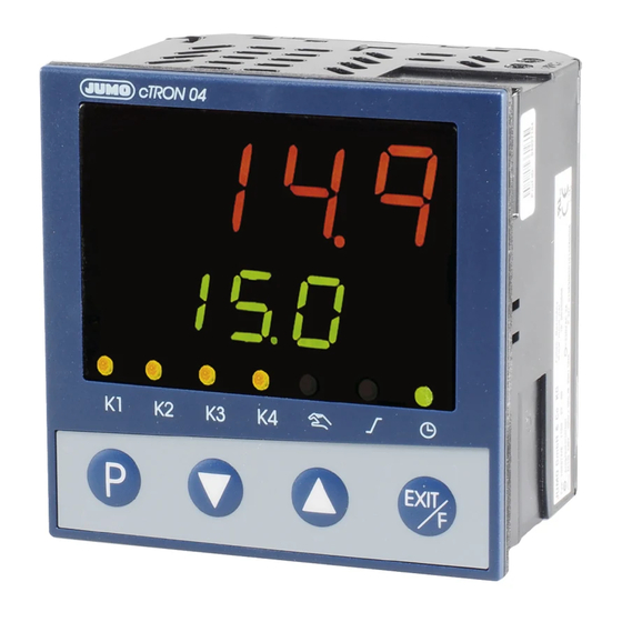
- Page 1 JUMO cTRON 04/08/16 Compact controller with timer and ramp function 702071 702072 702074 B 70.2070.0 Operating Manual 2008-11-10/00506527...
- Page 3 Content Introduction Preface ................... 5 Type designation ..............7 Scope of delivery ..............8 Accessories ................8 Installation Installation site and ambient conditions ......9 Dimensions ................9 Installation ................13 Electrical connection Installation notes ..............15 Electrical isolation ............... 17 Connection diagram 702071 ..........
- Page 4 Content Configuration level Analog input ................. 35 Controller ................38 Ramp function ..............40 Limit comparators ............... 42 Timer ..................45 Outputs ................. 49 Binary functions ..............51 Display/Operation/Service counter ........53 Interface ................58 Supplement Technical Data ..............59 Alarm and fault messages ..........
-
Page 5: Introduction
1 Introduction Preface Please read this manual before commissioning the device. Keep the manual in a place accessible to all users at all times. Your comments are appreciated and may assist us in improving this manual. All necessary settings are described in this operating manual. Manipulations not described in the manual or expressly forbidden will jeopardize your warranty rights. - Page 6 1 Introduction Note symbols TIP! This symbol refers to an Important information about the product or its handling or additional use. REFERENCE! This symbol refers to Further information in other sections, chapters or manuals.
-
Page 7: Type Designation
1 Introduction Type designation Basic type 702071 Type 702071 (nominal dimension 48mm x 48mm) 1 analog input, 2 binary inputs (alternative to logic output and input 0/2…10V, resp.) 702072 Type 702072 (nominal dimension 48mm x 96mm) 1 analog input, 2 binary inputs (one binary input alternative to input 0/2…10V) 702074 Type 702074 (nominal dimension 96mm x 96mm) 1 analog input, 2 binary inputs (one binary input alternative to input... -
Page 8: Scope Of Delivery
Sales No.: 70/00350260 USB interface PC interface with USB/TTL converter, adapter (socket connector) and adapter (pins); Sales No.: 70/00456352 Setup program PC program for device configuration, incl. JUMO-Startup; Sales No.: 70/00506060 Required hardware: • PC Pentium 100 or compatible •... -
Page 9: Installation
2 Installation Installation site and ambient conditions The ambient conditions at the installation site must meet the requirements specified in the technical data. Chapter 8.1 „Technical Data“ The device is not suitable for use in areas with an explosion hazard (Ex areas). - Page 10 2 Installation Legend referring to the following illustrations Connection for PC Panel cut-out interface adapter (setup plug) Type 702071...
- Page 11 2 Installation Type 702072...
- Page 12 2 Installation Type 702074...
-
Page 13: Installation
2 Installation Installation Type 702071 1. Insert the device from the front into the panel cut-out. 2. Push the fastening frame from the panel rear onto the device body and press the springs against the panel rear until the lugs engage in their slots and it is sufficiently fastened. - Page 14 2 Installation Type 702072 and 702074 1. Insert the device from the front into the panel cut-out. 2. From the panel rear, slide the mounting brackets into the guides on the sides of the case. The flat faces of the mounting brackets must make contact with the case.
-
Page 15: Electrical Connection
3 Electrical connection Installation notes • The choice of cable, the installation and the electrical connection of the device must conform to the requirements of VDE 0100 "Regulations on the Installation of Power Circuits with Nominal Voltages below 1000 V" or the appropriate local regulations. •... - Page 16 3 Electrical connection Installation information on conductor cross sections Type 702071 702072 702074 Lead ≤ 1.3mm ≤ 2.5mm 1 wire ≤ 1.0mm ≤ 1.5mm fine-strand, with core-end ferrule Plug-in terminal strips (srew terminals).
-
Page 17: Electrical Isolation
3 Electrical connection Electrical isolation (1) Analog input 2300 V AC (2) Binary inputs/ Output K3 (Logics) 30 V AC (3) Setup interface 50 V DC (4) Voltage supply (5) RS485 interface (6) Analog output 30 V AC (7) Outputs K1, K2 and K4 50 V DC (relay) 2300 V AC... -
Page 18: Connection Diagram 702071
3 Electrical connection Connection diagram 702071 0/4—20mA 0/2—10V (5.1) (5.2) 0/14V 0/2—10V (6.1) 0/4—20mA N(L-) (6.2) (6.3) (6.4) RxD/TxD L1(L+) Output 1 (K1): Output 2 (K2): Relay 230V AC/3A Relay 230V AC/3A Output 3 (K3): Logic 0/14V Output 4 (K4) (option): (alternative to binary input 1, Analog output or configurable) -
Page 19: Connection Diagram 702072, 702074
3 Electrical connection Connection diagram 702072, 702074 0/4—20mA 0/2—10V 0/14V (5.1) (5.2) 0/2—10V N(L-) (6.1) 0/4—20mA L1(L+) (6.2) (6.3) (6.4) RxD/TxD Output 1 (K1): Output 2 (K2): Relay 230V AC/3A Relay 230V AC/3A Output 3 (K3): Logic 0/14V Output 4 (K4) (option): Analog output or Relay 230V AC/3A (5.1) Binary input 1... - Page 20 3 Electrical connection...
-
Page 21: Operation
4 Operation Display and operating elements K1 K2 K3 K4 EXIT (1) Red 7-segment display (factory-setting: Process value); 4-digit, configurable decimal place (automatic adjustment on display overflow) (2) Green 7-segment display (factory-setting: Set point value); 4-digit, configurable decimal place, serves also for operator guide (display of parameter and level symbols) (3) Signals, yellow LED Switching states of the binary outputs 1...4... -
Page 22: Level Concept
4 Operation Level concept The parameters for device setting are organised at different levels. Operator level OPr Normal display Set points, process data, ... OPr/USEr USEr User level Up to any eigth parameters (ex-factory empty) Parameter level PArA PArA EXIT >2s . -
Page 23: User Level Configuration
4 Operation User level configuration A maximum of eight parameters to be available in the user level can be selected in the setup program. The user can assign a name to each parameter which appears on the device. Four characters that can be presented by a 7-segment display are permissible. -
Page 24: Level Inhibit
4 Operation TIP! The parameters selected here are displayed in the user level (UsEr). Then the operator level (OPr) is no longer visible. Select parameters from the operator level here, if required. Level inhibit Access to the individual levels can be inhibited. Code Operator, Parameter level... -
Page 25: Entries And Operator Prompting
4 Operation Entries and operator prompting Entering values When entries are made within the levels, the parameter symbol appears in the lower display. Select parameter Change value (bottom - green) (top - red) Parameter flashes 1. Select parameter by pressing 2. - Page 26 4 Operation Time entry A decimal place is mapped in the centre and on the right to display times. The time unit can be configured. Chapter 7.5 „Timer“ Select Parameter Change value (bottom - green) (top - red) Parameter flashes 1.
-
Page 27: Controller
4 Operation Controller Increase set point value Manual mode: Output value 30% EXIT >2s Normal display: Regulation to set point value 21,0 Further levels: USEr EXIT PArA Reduce set point value ConF alternatively Normal display In normal display, the controller regulates to the entered set point value. -
Page 28: Display Of The Software Version
4 Operation Changing to the manual mode In the manual mode, the controller output value can be changed manually. 1. Change to the manual mode using function key (> 2s) (ex-factory setting) The output value is displayed in percent in the lower display. The "Manual mode active"... -
Page 29: Operator Level
5 Operator level Operator level OPr Normal display Set point values, process data, ... EXIT >2s or timeout Navigation principle one level one level forward backward EXIT 1. Operator level ( ) only visible next/previous if no user level ( ) exists USEr parameter... - Page 30 5 Operator level Parameters Depending on the configuration, the following values are displayed: Symbol Meaning Set point value 1 (can be edited) Set point value 2 (can be edited), only when switching over to set point value 2 v Chapter 7.7 „Binary functions“ Ramp set point value (only if configured) v Chapter 7.3 „Ramp function“...
-
Page 31: Parameter Level
6 Parameter level Normal display OPr/USEr PArA Parameter level PArA EXIT >2s or timeout Navigation principle one level one level forward backward EXIT 1. Either the operator ( ) or next/previous the user level ( USEr ) exists parameter Levels can be inhibited. Chapter 4.4 „Level inhibit“... - Page 32 6 Parameter level Cycle time of 0.0… For a switching output, the cycle C Y1 20.0… time should be selected so that, on output 999.9s one hand, no inadmissible process value fluctuations are generated 0.0… C Y2 caused by the cycled energy supply 20.0…...
-
Page 33: Configuration Level
7 Configuration level Normal display OPr/USEr PArA Configuration level ConF ConF - Analog input EXIT >2s - Controller Cntr oder timeout - Ramp function rFCt - Limit comparators Navigation principle - Timer tFCt Outputs OutP one level one level - Binary functions binF forward backward... - Page 34 7 Configuration level TIP! For activation of binary input 2 the setup program is re- quired (Hardware assistant). Analog selector Some parameters in the Configuration level allow users to select from a series of analog values. The list below shows all available signals. Value Description deactivated...
-
Page 35: Analog Input
7 Configuration level Analog input One analog input is available. ConF I nP -> -> Parameters Value/ Description Selection RTD temperature probe Pt100 Sensor type 3 wire SEnS RTD temperature probe Pt1000 3 wire RTD temperature probe Pt100 2 wire RTD temperature probe Pt1000 2 wire KTY 2 wire... - Page 36 7 Configuration level Parameters Value/ Description Selection -1999… The measured value correction (offset) is Measured value 0… used to correct a measured value by a offset +9999 certain amount upward or downward. Examples: OFFS Measured valueOffset Displayed value 294.7 +0.3 295.0 295.3 - 0.3...
- Page 37 7 Configuration level Parameters Value/ Description Selection deg. Celsius Temperature deg. Fahrenheit unit U n i t Unit for temperature values 0… Resistance in ohms at 25°C/77°F for „KTY Correction value 2000… 2-wire“ probe type KTY at 25°C 4000 Setting in the setup program (Setup) (->...
-
Page 38: Controller
7 Configuration level Controller Controller type and controller input values, set point limit values, functions for manual mode and the presettings of self-optimization are set here. ConF Cntr -> -> Parameters Value/ Description Selection 2-state controller Controller type 3-state controller CtyP Modulating controller Continuous controller... - Page 39 7 Configuration level Parameters Value/ Description Selection (analog Determines the source of the controller Process value process value. selector) for controller v Page 34, Analog selector Analog input -100… Defines the output value after switching to Output value, manual mode. +101 manual mode 101 = last output value...
-
Page 40: Ramp Function
7 Configuration level Ramp function The device can be operated as a fixed value controller with and without ramp function. When the ramp function is active, a new temperature set point value is controlled along a ramp and no longer as a step. It is possible to realize an ascending or descending ramp function. - Page 41 7 Configuration level Parameters Value/ Description Selection 0.0… Value of ramp rate Ramp 999.9 (for functions 1 to 3 only) rate rAS L 0…9999 Range of the tolerance band (in Kelvin) Tolerance band around the set point value toLP 0 = Tolerance band inactive (for functions 1 to 3 only) For the ramp function, it is possible to enter a tolerance band around the set point...
-
Page 42: Limit Comparators
7 Configuration level Limit comparators Limit comparators (threshold monitors, limit contacts) can be used to monitor the limit comparator process value against a fixed alarm value or an alarm value depending on the limit comparator set point value. When an alarm value is exceeded, a signal can be output or an internal controller function initiated. - Page 43 7 Configuration level HySt HySt Fixed alarm value AL The limit comparator functions lk7 and lk8 monitor the process value x for a fixed alarm value AL to be set. HySt HySt...
- Page 44 7 Configuration level ConF -> -> -> Parameters Value/ Description Selection no function Function FnCt -1999… Alarm value (limit value) to be monitored Alarm value 0… (see limit comparator functions lk1...lk8: +9999 alarm value AL) Alarm value range for lk1 and lk2: 0...9999 0…...
-
Page 45: Timer
7 Configuration level Timer Timer signal A timer signal (tF1) is provided which can be transmitted via binary outputs or used for internal links, e. g. to switch off the controller (output value 0%) or to toggle the set point values. Chapter 7.6 „Outputs“... - Page 46 7 Configuration level Timer in connection with the ramp function In general, set point values can also be moved to with the ramp function. For timer functions started via the tolerance limit, only the set point value (ramp limit value) is monitored. Timer signals The additional signals "Timer running", "Timer waiting"...
- Page 47 7 Configuration level ConF tFCt -> -> Parameters Value/ Description Selection no function Function Timer FnCt Timer for time-delayed control Timer is manually started using the Start condition function key or the binary signal. Strt Manual (see above) and automatic start after power ON.
- Page 48 7 Configuration level Parameters Value/ Description Selection 0…9999 The set timer time only elapses when the Tolerance band process value has reached the tolerance toLt band. 0 = Start without tolerance band The tolerance band (in Kelvin) is symmetrical in relation to the SP set point value.
-
Page 49: Outputs
7 Configuration level Outputs The configuration of the device outputs is subdivided in binary outputs (OutL) and analog outputs (OutA). Binary outputs are relays and logic outputs. The switching states of the binary outputs 1 to 4 are shown in the display (K1 to K4). Binary outputs Output 1 (Out1) = Relay Output 2 (Out2) = Relay... - Page 50 7 Configuration level Analog output The device can optionally be equipped with an analog output. ConF OutP OutA -> -> -> Parameters Value/ Description Selection (Analog Function of the output Function selector) FnCt Controller output value 0...10V Type of signal 2...10V S i G n 0...20mA...
-
Page 51: Binary Functions
7 Configuration level Binary functions In terms of this manual a function initiated by a binary signal is called "binary function". Several binary functions can be realized by using the signals of binary inputs, limit comparators, timer and ramp function. Switching behavior The following binary functions react to switch-on edges: •... - Page 52 7 Configuration level ConF b i nF -> -> Parameters Value/ Description Selection no function Binary inputs Start self-optimization b i n 1 Abort self-optimization b i n 2 Change to manual mode Controller off (controller outputs are switched off) Limit Switch on controller comparators...
-
Page 53: Display/Operation/Service Counter
7 Configuration level Display/Operation/Service counter Both displays can be adapted to the respective requirements by the configuration of the displayed value, the decimal place and the automatic change (timer). The time-out of the operation, the function key assignment and the level inhibit can also be configured. - Page 54 7 Configuration level Parameters Value/ Description Selection no digit after the decimal point Decimal place one digit after the decimal point dECP two digits after the decimal point If the value to be displayed cannot be shown including the programmed decimal point, the number of digits after the decimal point are automatically reduced.
- Page 55 7 Configuration level Parameters Value/ Description Selection None Access to the individual levels can be Level inhibited. inhibit Setting in the setup program (Setup) (-> Display/Operation/Service counter -> Operation): -None -Configuration level -Parameter and configuration level -Operator, parameter and configuration level The setting is independent of binary function „Level inhibit“.
- Page 56 7 Configuration level Parameters Value/ Description Selection Number: Limit value for service counter Service interval 0… (when select. „Number“ in increm. of 1000) (Setup) 9999000 0 = Service counter switched off o C A L The service counter can be used to Time (h): monitor a binary signal in respect to number (switch-on edge) or time (ON...
- Page 57 7 Configuration level Parameters Value/ Description Selection Signal to be Controller Selection of the binary signal to be output 1 monitored monitored Setting in the setup program (Setup) (-> Display/Operation/Service counter -> Service counter): - deactivated - Controller output 1 - Controller output 2 - Binary input 1 - Binary input 2...
-
Page 58: Interface
7 Configuration level Interface The device can be integrated into a data network (Modbus) via an optional RS485 interface. ConF I nt F -> -> Parameters Value/ Description Selection 9600 bps Baud rate 19200 bps bdrt 38400 bps 8 data bits, 1 stop bit, no parity Data 8 data bits, 1 stop bit, odd parity format... -
Page 59: Supplement
8 Supplement Technical Data Thermocouple input Designation Measuring Measuring Ambient range accuracy temperature coefficient ≤ 0.25% Fe-CuNi „L“ -200… +900°C 100ppm/K ≤ 0.25% Fe-CuNi „J“ 60584 -200…+1200°C 100ppm/K ≤ 0.25% Cu-CuNi „U“ -200… +600°C 100ppm/K ≤ 0.25% Cu-CuNi „T“ 60584 -200…... - Page 60 8 Supplement Designation, Measuring Measuring Ambient Connection type range accuracy temperature coefficient Pt1000 EN 60751 -200…+850°C 50ppm/K ≤ 0.2% 2 wire connection ≤ 0.1% 3 wire connection KTY11-6 -50…+150°C 50ppm/K ≤ 2.0% 2 wire connection Sensor lead resistance: max. 30Ω per lead with three wire circuit Measuring current: approx.
- Page 61 8 Supplement Measuring circuit monitoring In the event of a fault, the outputs change to defined statuses (configurable) Sensor Overrange/ Probe/ Probe/ underrange lead short- lead break circuit Thermocouple • • RTD temperature • • • probe Voltage 2…10V • •...
- Page 62 8 Supplement Controller Controller type 2-state, 3-state, modulating controller, continuous controller Controller structures P/PI/PD/PID A/D converter 16 bit resolution Sampling cycle time 250ms Timer Accuracy ±0.5% ± 25ppm/K Electrical data Supply voltage AC 110…240V -15/+10%, 48…63Hz (switch mode PSU) AC/DC 20...30V, 48...63Hz Electrical acc.
- Page 63 8 Supplement Case Case type Plastic case for panel mounting acc. to IEC 61554 Installation depth Type 702071 90.5mm Type 702072 67.0mm Type 702074 70.0mm Ambient/storage -5…+55°C / -40…+70°C temperature range Ambient conditions rel. humidity < 90% annual average, no condensation Operating position Protection type...
-
Page 64: Alarm And Fault Messages
8 Supplement Alarm and fault messages Display Cause Fault remedy Test/repair/replace ALrt Binary function for Carry out the measure intended for which a text display this case (factory- was configured is specific text, active can be changed) -1999 Underrange for the Is the medium being measured value being within the range (too hot? too... -
Page 65: Self-Optimization
8 Supplement Self-optimization Principle Self-optimization (SO) is carried out according to the oscillation method and establishes the optimum controller parameters for PID or PI controllers. Depending on the configured controller type, the following controller parameters are defined: Proportional band (Pb), derivative time (dt), reset time (rt), cycle times (Cy), filter time constant (dF) Depending on the range of the control deviation, the controller selects between to methods a or b:... - Page 66 8 Supplement Furthermore, the following five points should be taken into considera- tion, checked and, if necessary, adjusted, prior to starting self-optimi- zation: • Is the suitable controller type configured? • Check and/or adjust the control action of the controller •...
- Page 68 JUMO GmbH & Co. KG Street address: Moritz-Juchheim-Straße 1 36039 Fulda, Germany Delivery address: Mackenrodtstraße 14 36039 Fulda, Germany Postal address: 36035 Fulda, Germany Phone: +49 661 6003-0 Fax: +49 661 6003-607 E-mail: mail@jumo.net Internet: www.jumo.net JUMO Instrument Co. Ltd.
Need help?
Do you have a question about the cTRON 04 and is the answer not in the manual?
Questions and answers