Sign In
Upload
Download
Table of Contents
Contents
Add to my manuals
Delete from my manuals
Share
URL of this page:
HTML Link:
Bookmark this page
Add
Manual will be automatically added to "My Manuals"
Print this page
×
Bookmark added
×
Added to my manuals
Manuals
Brands
JUMO Manuals
Controller
diraTRON Series
Interface description
JUMO diraTRON Series Interface Description
Compact controller/digital indicator
Hide thumbs
1
2
Table Of Contents
3
4
5
6
7
8
9
10
11
12
13
14
15
16
17
18
19
20
21
22
23
24
25
26
27
28
29
30
31
32
33
34
35
36
37
38
39
40
page
of
40
Go
/
40
Contents
Table of Contents
Bookmarks
Table of Contents
Table of Contents
1 Introduction
Safety Information
Intended Use
Qualification of Personnel
Content of this Document
2 Interface
3 Modbus Protocol Description
Master-Slave Principle
Transmission Mode
Chronological Sequence of Communication
Structure of a Modbus Telegram
Device Address (RS485)
Function Codes
Reading N Words
Writing One Word
Writing N Words
Transmission Formats
Integer Values
Float Values
Checksum (CRC16)
Error Messages
Modbus Error Codes
Error Messages for Invalid Values
4 Modbus Addresses
Data Types and Access Types
Addresses
Configuration Data
Commands
Process Values
Advertisement
Quick Links
1
Safety Information
2
Introduction
3
Interface
4
Master-Slave Principle
5
Function Codes
6
Configuration Data
Download this manual
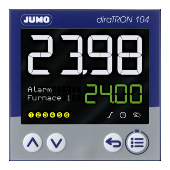
JUMO diraTRON/diraVIEW 104/108/116/132
Compact controller/digital indicator
Interface Description
70211000T92Z001K000
V3.00/EN/00688816/2019-10-15
Table of
Contents
Previous
Page
Next
Page
1
2
3
4
5
Advertisement
Table of Contents
Need help?
Do you have a question about the diraTRON Series and is the answer not in the manual?
Ask a question
Questions and answers
Related Manuals for JUMO diraTRON Series
Controller JUMO diraTRON 104 Operating Manual
Compact controller (104 pages)
Controller JUMO diraTRON 104 Brief Instructions
Compact controller (33 pages)
Controller JUMO DICON 401 Operating Manual
Universal profile controller, universal profile generator (100 pages)
Controller JUMO DICON 400 Interface Description
Universal process and profile controller (44 pages)
Controller JUMO DICON touch Operating Manual
Two-channel process and program controller with paperless recorder and touchscreen 8.9 cm (3.5") (192 pages)
Controller JUMO DICON touch Quick Start Manual
B 703571.7 two-channel process and program controller paperless recorder and touchscreen (128 pages)
Controller JUMO DICON touch Datasheet
Two-channel process and program controller with paperless recorder and touchscreen (24 pages)
Controller JUMO DICON touch Interface Manual
Two-channel process and program controller with paperless recorder and touchscreen (86 pages)
Controller JUMO DICON touch Manual
Two-channel process and program controller with paperless recorder and touchscreen 8.9 cm 3.5" (60 pages)
Controller JUMO DICON touch Operating Manual
Two/four-channel process and program controller with paperless recorder and 8.9 cm 3.5" touchscreen (196 pages)
Controller JUMO diraVIEW Series Interface Description
Compact controller/digital indicator (40 pages)
Controller JUMO diraVIEW 104 Interface Description
Compact controller/digital indicator (40 pages)
Controller JUMO diraVIEW 108 Interface Description
Compact controller/digital indicator (40 pages)
Controller JUMO diraVIEW 132 Interface Description
Compact controller/digital indicator (40 pages)
Controller JUMO diraVIEW 116 Interface Description
Compact controller/digital indicator (40 pages)
Controller JUMO DICON 500 Interface Description
Universal process and profile controller (44 pages)
This manual is also suitable for:
Diraview series
Diratron 116
Diratron 132
Diratron 104
Diraview 104
Diratron 108
...
Show all
Diraview 132
Diraview 116
Diraview 108
Table of Contents
Print
Rename the bookmark
Delete bookmark?
Delete from my manuals?
Login
Sign In
OR
Sign in with Facebook
Sign in with Google
Upload manual
Upload from disk
Upload from URL


Need help?
Do you have a question about the diraTRON Series and is the answer not in the manual?
Questions and answers