JUMO DICON touch Quick Start Manual
B 703571.7
two-channel process and program controller
paperless recorder and touchscreen
Hide thumbs
Also See for DICON touch:
- Operating manual (196 pages) ,
- Interface manual (86 pages) ,
- Manual (60 pages)
Table of Contents
Advertisement
Available languages
Available languages
Quick Links
Download this manual
See also:
Operating Manual
Advertisement
Chapters
Table of Contents

Related Manuals for JUMO DICON touch


Summary of Contents for JUMO DICON touch
- Page 1 JUMO DICON touch Zweikanal-Prozess- und Programmregler Two-channel process and program controller paperless recorder and touchscreen B 703571.7 Kurzanleitung Quick start guide 2015-03-01/00608676...
-
Page 3: Table Of Contents
Inhalt Einleitung ............11 Sicherheitshinweise . - Page 4 Inhalt Anzeige- und Bedienkonzept ..........35 Gerätemenü...
- Page 5 Inhalt Sonderfunktionen ..........63 10.1 Touchscreen kalibrieren .
- Page 6 Inhalt...
-
Page 7: Einleitung
1 Einleitung Sicherheitshinweise Allgemein Diese Anleitung enthält Hinweise, die Sie zu Ihrer eigenen Sicherheit sowie zur Vermeidung von Sachschäden beachten müssen. Diese Hinweise sind durch Zeichen unterstützt und wer- den in dieser Anleitung wie gezeigt verwendet. Lesen Sie diese Anleitung, bevor Sie das Gerät in Betrieb nehmen. Bewahren Sie die Anleitung an einem für alle Benutzer jederzeit zugänglichen Platz auf. -
Page 8: Darstellungsarten
1 Einleitung & WEITERE INFORMATION! Dieses Zeichen wird in Tabellen verwendet und weist auf weitere Informationen im Anschluss an die Tabelle hin. ENTSORGUNG! Dieses Gerät und, falls vorhanden, Batterien gehören nach Beendigung der Nutzung nicht in die Mülltonne! Bitte lassen Sie sie ordnungsgemäß und umweltschonend entsorgen. 1.1.3 Darstellungsarten Menüstruktur... -
Page 9: Beschreibung
1 Einleitung Beschreibung Der DICON touch ist ein zweikanaliger universeller Prozess- und Programmregler, der über ein brillantes Display visualisiert und mit Touchscreen intuitiv bedient wird. Die beiden Regelkanäle verfügen über den bewährten JUMO-Regelalgorithmus mit zwei mög- lichen Optimierungsvarianten. Diese ermöglichen eine einfache und hochgenaue Inbetrieb- nahme. - Page 10 1 Einleitung...
-
Page 11: Geräteausführung Identifizieren
2 Geräteausführung identifizieren Bestellangaben Grundtyp 703571 JUMO DICON touch - Zweikanal-Prozess- und Programmregler mit RS 485 Schnittstelle Ausführung Standard mit werkseitigen Einstellungen Kundenspezifische Konfiguration (Angaben im Klartext) Sprache der Gerätetexte Deutsch Englisch Französisch Eingang IN10 nicht belegt Analogeingang (universal) Eingang IN11... - Page 12 2 Geräteausführung identifizieren 1 Relais (Wechsler) 2 Relais (Schließer) 1 Halbleiterrelais 230 V, 1 A 1 Logikausgang 0/22 V, max. 30 mA 2 Logikausgänge 0/12 V, 20 mA 1 Analogausgang 2 PhotoMOS®-Relais Ausgänge OUT9/10 (steht nicht zur Verfügung bei Belegung mit Baugruppe 20 auf OUT5/6) keine 1 Relais (Wechsler) 2 Relais (Schließer)
-
Page 13: Lieferumfang
Typenzusätze nacheinander aufführen und durch Komma trennen. Lieferumfang • 1 Regler in der bestellten Ausführung • 1 Betriebsanleitung B 703571.0 • 1 Schalttafeldichtung 4 Befestigungselemente für Schalttafeleinbau Allgemeines Zubehör Artikel Teile-Nr. Programmeditor/Startup 00607139 Setup/Programmeditor 00606496 PCA3000/PCC JUMO Softwarepaket 709701/709702 00431884 USB-Kabel A-Stecker Mini-B-Stecker 3 m 00506252... -
Page 14: Zubehör
2 Geräteausführung identifizieren Zubehör Artikel Teile-Nr. Baugruppen für Optionssteckplätze: 1 Analogeingang (universal) 00581159 1 Relaisausgang (Wechsler) 00581160 2 Relaisausgänge (Schließer) 00581162 1 Logikausgang DC 0/22 V, max. 30 mA 00581165 2 Logikausgänge DC 0/12 V max. 20 mA 00581168 1 Halbleiterrelais AC 230 V, 1 A 00581164 2 Halbleiterrelais AC 230 V, 1 A für Motor- 00621574... -
Page 15: Typenschild
2 Geräteausführung identifizieren Typenschild Lage Das Typenschild ist auf dem Gehäuse aufgeklebt. Inhalt Die Typenschilder beinhalten wichtige Informationen. Unter anderem sind dies: Beschreibung Bezeichnung auf dem Typenschild Gerätetyp (A) Spannungsversorgung, Leistungsaufnahme (B) Fabrikations-Nummer (C) F-Nr Teile-Nr. (D) Gerätetyp (Typ) Die Angaben auf dem Typenschild mit der Bestellung vergleichen. Die gelieferte Geräteausführung mit Hilfe der Bestellangaben (Typenschlüssel) identifizieren. - Page 16 2 Geräteausführung identifizieren...
-
Page 17: Montage
3 Montage Montageort und klimatische Bedingungen Der Montageort soll möglichst erschütterungsfrei, staubfrei und frei von aggressiven Medien sein. Regler möglichst weit entfernt von Entstehungsquellen elektromagnetischer Felder ein- bauen, wie sie z. B. durch Frequenzumrichter oder Hochspannungs-Zündtransformatoren ent- stehen. Die Bedingungen am Montageort müssen folgenden Umwelteinflüssen entsprechen: 3.1.1 Elektrische Daten Spannungsversorgung... -
Page 18: Abmessungen
3 Montage Einbautiefe max. 130 mm Befestigung 4 Befestigungselemente Gebrauchslage beliebig (Betrachtungswinkel des TFT-Farbbild- horizontal ±65°, vertikal +40 ... -65° schirms berücksichtigt) Schutzart Frontseitig IP66, rückseitig IP20, nach DIN EN 60529 Gewicht (voll bestückt) ca. 1000 g Abmessungen (20) USB-Host-Schnittstelle (21) USB-Device-Schnittstelle für Setup (22) -
Page 19: Dicht-An-Dicht Montage
3 Montage Dicht-an-Dicht Montage Werden mehrere Geräte in einer Schalttafel über- oder nebeneinander montiert, müssen die Schalttafelausschnitte horizontal von 35 mm und vertikal mindestens 80 mm voneinander ent- fernt sein. Einbau in Schalttafelauschnitt Schritt Tätigkeit Mitgelieferte Schalttafeldichtung (1) von hinten auf das Gerät aufsetzen Das Gerät von vorn in den Schalttafelausschnitt einsetzen und auf korrekten Sitz der Schalttafeldichtung achten, damit kein Wasser oder Schmutz in das Gehäuse eindringen kann. -
Page 20: Pflege Und Behandlung Der Frontfolie
3 Montage Pflege und Behandlung der Frontfolie Die Frontplatte kann mit handelsüblichen Wasch-, Spül- und Reinigungsmitteln gesäubert wer- den. HINWEIS! Die resistive Touchscreen-Folie reagiert auf Fingerdruck oder ist mit handelsüblichen Stiften mit einer abgerundeten Kunststoffspitze bedienbar. VORSICHT! Spitze Werkzeuge verursachen Kratzer und können die Folie beschädigen! Die Frontplatte ist nicht beständig gegen aggressive Säuren und Laugen, Scheuermittel und die Säuberung mit Hochdruckreinigern! Bedienen Sie das Gerät nicht mit spitzen Gegenständen! -
Page 21: Elektrischer Anschluss
4 Elektrischer Anschluss Installationshinweise VORSICHT! Der Auslieferungszustand des Gerätes entspricht bei der ersten Inbetriebnahme möglicher- weise nicht der vorgesehenen Anwendung (z. B. Regler2 inaktiv). Dies kann ein undefiniertes Verhalten der Anlage zur Folge haben. Deshalb sollten während der Inbetriebnahme nach Möglichkeit keine Aktoren angeschlos- sen und Laststromkreise getrennt sein. -
Page 22: Galvanische Trennung
4 Elektrischer Anschluss Galvanische Trennung Analogausgang Analogeingang IN8 AC 30 V AC 30 V DC 50 V DC 50 V Analogeingang IN11 Relaisausgänge AC 30 V AC 3600 V DC 50 V PhotoMOS® Halbleiterrelais Digitaleingang 1 = DC 50 V, I = 200 mA max. -
Page 23: Anschlussplan
4 Elektrischer Anschluss Anschlussplan GEFAHR! Hier sind Arbeiten an gefährlicher elektrischen Spannung (230 V) durchzuführen. Es besteht die Gefahr eines Stromschlags. Alle Stromkreise vor der Verdrahtung spannungsfrei schalten. Der elektrische An- schluss darf nur von Fachpersonal durchgeführt werden. 4.3.1 Anschlusselemente Analogeingang IN8 Analogeingang IN9 Optionssteckplatz Analogeingang IN10... -
Page 24: Analogeingänge
4 Elektrischer Anschluss 4.3.2 Analogeingänge Eingang IN8, IN9 serienmäßig Eingang (IN10), (IN11) ist über Optionsplatinen um 2 Analogeingänge erweiterbar Anschluss (Anschlussele- Symbol und Klemmenbezeichnung ment) Eingang Thermoelement (1) IN8 (2) IN9 (3) IN10 (4) IN11 Widerstandsthermometer Zweileiterschaltung Widerstandsthermometer Dreileiterschaltung Spannung DC 0(2) ... 10 V Spannung DC 0 ... -
Page 25: Analogausgänge
4 Elektrischer Anschluss 4.3.3 Analogausgänge Ausgang OUT 3/4 ... 11/12 ist über Optionsplatinen um 1 Analogausgang erweiterbar Anschluss (Anschlussele- Symbol und Klemmenbezeichnung ment) Eingang 1 Analogausgang (8) OUT3/4 DC 0/2 ... 10 V oder DC 0/ (9) OUT5/6 4 ... 20 mA (10) OUT7/8 (konfigurierbar) (11) OUT9/10... - Page 26 4 Elektrischer Anschluss Ausgänge OUT 3/4 ... 11/12 sind über folgende Optionsplatinen erweiterbar Anschluss (Anschlussele- Symbol und Klemmenbezeichnung ment) Ausgang 1 Relaisausgang (Wechsler) (8) OUT3/4 (9) OUT5/6 (10) OUT7/8 (11) OUT9/10 (12) OUT11/12 2 Relaisausgänge (Schließer) 1 Halbleiterrelais AC 230 V, 1 A 1 Logikausgang DC 0/22 V, max.
-
Page 27: Digitalausgänge
4 Elektrischer Anschluss Anschluss (Anschlussele- Symbol und Klemmenbezeichnung ment) Ausgang 2 Halbleiterrelais AC 230 V, 1 A (zur Ansteuerung von Motor- stellantrieben mit Rechts- und Linkslauf, galvanisch getrennt) Eine Kombination von Netzspannungs- und Schutzkleinspannungskreisen an einer 2-fach-Schließer-Option ist nicht zulässig. PhotoMOS ist eingetragenes Markenzeichen der Panasonic Corporation. -
Page 28: Spannungsversorgung (Nach Typenschild)
4 Elektrischer Anschluss 4.3.7 Spannungsversorgung (nach Typenschild) AC 230V (DC 24V) Anschluss (Anschlussele- Symbol und Klemmenbezeichnung ment) Schutzleiter Neutralleiter N (L-) Außenleiter L1(L+) 4.3.8 Schnittstellen Schnittstellen USB-Device, USB-Host und COM1 serienmäßig Anschluss (Anschlussele- Symbol und Klemmenbezeichnung ment) USB-Device-Schnittstelle (21) USB-Host (20) COM1 Serielle Schnittstelle (13) - Page 29 4 Elektrischer Anschluss Schnittstelle COM2 über Optionsplatinen erweiterbar Anschluss (Anschlussele- Symbol und Klemmenbezeichnung ment) Ethernet (14) 1 TX+ Sendedaten + 2 TX- Sendedaten - 3 RX+ Empfangsdaten + 6 RX- Empfangsdaten - Serielle Schnittstelle RS422 1 RxD+ Empfangsdaten + (galvanisch getrennt) 2 RxD- Empfangsdaten - 3 TxD+...
- Page 30 4 Elektrischer Anschluss...
-
Page 31: Bedienung
5 Bedienung Anzeige- und Bedienkonzept Der DICON touch wird über den resistiven Touchscreen bedient und reagiert auf Fingerdruck. Auch handelsübliche Stifte mit einer abgerundeten Kunststoffspitze können verwendet werden. (werkseitig abgeschaltet) (werkseitig abgeschaltet) nur bei Typenzusatz 223 Datenaufzeichnung und Auswertung nur bei Typenzusatz 213 2 Funktionschaltflächen... -
Page 32: Gerätemenü
5 Bedienung Gerätemenü Alle Funktionen im Gerätemenü werden in den nachfolgenden Kapiteln der Betriebsanleitung B703571.0de erklärt. Kapitel 6 "Anmeldung", Seite 43 B 703571.0 - Kapitel 7 "Anwenderebene (Log-In)", Seite 43 Kapitel 7 "Programmverwaltung", Seite 45 B 703571.0 - Kapitel 10 "Funktionsebene", Seite 53 B 703571.0 - Kapitel 8 "Parametrierung", Seite 49 B 703571.0 -... -
Page 33: Bilder Im Bedienring
5 Bedienung Bilder im Bedienring Startbildschirm Nach dem Einschalten erscheint zunächst die Weltkugel, bis die Gerätesoftware gestartet ist. Danach erscheint das Reglerbild1 (werkseitig eingestellt). Mit dem Icon rechts unten können alle im Bedienring definierten Bilder nacheinander abgeru- fen werden. Einstellungen für Bildschirm siehe B 703571.0- Kapitel 12.10 "Bildschirm", Seite 104 ... - Page 34 5 Bedienung Handbetrieb starten Im Handbetrieb wird dem Regler ein Stellgrad fest vorgegeben. Die Bilder zeigen zunächst den aktiven RegIer, dessen Stellgrad bei ca.40% liegt. Schritt Tätigkeit Handsymbol berühren (Bleistift erscheint bei Stellgradanzeige) Bleistift berühren, den Handstellgrad eingeben und bestätigen (grüner Pfeil) Der Reglerbetrieb wird unterbrochen und der Regler1 arbeitet nunmit einem festen Stell- grad von 20% (Handsymbol erscheint neben dem grünen Sollwert).
-
Page 35: Programmregler
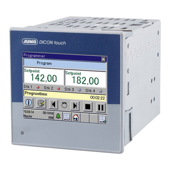
5 Bedienung 5.5.2 Programmregler HINWEIS! Dieses Bild ist werkseitig nicht vorhanden und erscheint nur, wenn der Typenzusatz Pro- grammregler freigeschaltet und konfiguriert ist. Kapitel 2.1 "Bestellangaben", Seite 15 werkseitig Kein Programm ist vorhanden. Um ein Programm zu erstellen gibt es folgende Möglichkeiten: Sollwertkurven am Gerät eingeben ... -
Page 36: Übersichtsbild 1,2
5 Bedienung Selbstoptimierung B 703571.0- Kapitel 12.6.3 "Regler Selbstoptimierung", Seite 80 5.5.3 Übersichtsbild 1,2 werkseitig Es stehen 2 Übersichtsbilder zur Verfügung, die keine Variablen enthalten. Die darzustellenden Variablen können konfiguriert werden. B 703571.0- Kapitel 12.10.8 "Übersichtsbild 1, 2", Seite 110 5.5.4 Registrierbild werkseitig... -
Page 37: Prozessbild
5 Bedienung 5.5.5 Prozessbild werkseitig Dieses Bild ist frei konfigurierbar und werkseitig leer. Ein Hintergrundbild Ihrer Anlage kann hin- terlegt und mit allen Prozesswerte des Gerätes animiert werden. Für die grafische Gestaltung ist das Setup-Programm erforderlich. B 703571.0 - Kapitel 13.11 "Prozessbild", Seite 151... - Page 38 5 Bedienung...
-
Page 39: Anmeldung
6 Anmeldung Einzelne Ebenen im Gerätemenü sind mit Benutzer und Passwort geschützt. Der Ebenen- schutz wird in der Benutzerliste über 5 verschiedene Benutzer über das Setup-Programm de- finiert. Nach Eingabe des Passworts kann jeder Benutzer die erlaubten „Rechte“ ausführen. Wenn es zugelassen ist, können die Rechte und Passwörter auch am Gerät verändert werden. Durch Berühren der Schaltfläche links unten öffnet sich das Fenster Gerätemenü. -
Page 40: Login
6 Anmeldung Login Hier die Anmeldung als Master (mit dem werkseitigen Passwort 9200): Jetzt ist Benutzer1 angemeldet und alle Funktionen verfügbar, die unter „Rechte“ eingestellt wurden. Logout Sobald man angemeldet ist wird die Schaltfläche Log-Out nicht mehr grau unterlegt, sondern kann zum Ausloggen berührt werden. -
Page 41: Programmverwaltung
7 Programmverwaltung Programmkurven eingeben 10 Programme können am Gerät oder im Setup-Programm eingegeben werden. 7.1.1 Am Gerät Schritt Tätigkeit Programmnamen und -icon eingeben ersten Abschnitt eingeben: Ist der Programmspeicher leer wird der Abschnitt rot unterlegt. Jeder Abschnitt besteht aus: Sollwert 1 und 2, Abschnittszeit, Steuerkontakte, Toleranz- band, Anzahl der Wiederholungen vom Startabschnitt an und Parametersatz. -
Page 42: Über Setup-Programm
7 Programmverwaltung 7.1.2 Über Setup-Programm Schritt Tätigkeit Setup-Programm starten und im Menü Programmeditor->Programmverwaltung anklicken Abschnitte in die Tabelle eingeben Mit der Programmsimulation wird die Tabelle graphisch dargestellt... -
Page 43: Abschnittslaufzeit
7 Programmverwaltung Schritt Tätigkeit Setup-Datei speichern und Setupdaten ins Gerät übertragen Erscheint ein grünes Icon (Smiley), sind die Programme korrekt übertragen worden. ➥ 2 Programmkurven sind nun im Gerät und können an einem beliebigen Abschnitt zu einer einstellbaren Zeit gestartet werden. Die Programme laufen zeitsynchron ab. 7.1.3 Abschnittslaufzeit Zeitspanne, die bis zum nächsten Abschnitt verstreicht. -
Page 44: Toleranzband
7 Programmverwaltung 7.1.6 Toleranzband B 703571.0 - Kapitel 12.6.7 "Rampenfunktion", Seite 93 7.1.7 Anzahl Wiederholungen Hier wird die Anzahl der Wiederholungen von einem bestimmten Startabschnitt an eingegeben. 7.1.8 Startabschnitt Abschnitt von dem aus die Wiederholung beginnen soll. Beispiel 7.1.9 Parametersatz Für jeden Reglerkanal stehen Parametersatz 1...4 zur Verfügung, die abschnittsweise umge- schaltet werden können... -
Page 45: Parametrierung
HINWEIS! Die in diesem Kapitel beschriebenen Parameter können sowohl mit dem Setup-Programm als auch am DICON touch eingegeben werden. Hier werden die Parameter eingestellt, die unmit- telbar mit der Anpassung des Reglers an die Regelstrecke zu tun haben, nachdem die Anlage in Betrieb genommen wurde. -
Page 46: Regler \ Parametersätze
8 Parametrierung Parameter Einstellung Beschreibung Start Sommerzeit Monat: März Zu diesem Zeitpunkt findet die Umschal- tung statt. Woche: letzte Woche Wochentag: Sonntag Uhrzeit: 02:00:00 Ende Sommerzeit Monat: Oktober Zu diesem Zeitpunkt findet die Umschal- tung statt. Woche: letzte Woche Wochentag: Sonntag Uhrzeit: 03:00:00 Regler \ Parametersätze Setup-Dialog... - Page 47 8 Parametrierung Parameter Einstellung Beschreibung Proportional- 0 ... 9999 Größe des proportionalen Bereichs bereich 1 Bei Xp = 0 ist die Reglerstruktur nicht (Xp1) wirksam (Verhalten wie Grenzwertüber- wachung)! Proportional- 0 ... 9999 Bei einem Stetigen Regler muss Xp > 0 bereich 2 sein.
- Page 48 8 Parametrierung Parameter Einstellung Beschreibung Min. Stellgrad- -100 ... +100 % Zulässiger minimaler Stellgrad (nur bei Xp > 0 wirksam) begrenzung (Y2) Minimale Relais- 0 ... 60 s Begrenzung der Schalthäufigkeit bei einschaltdauer 1 schaltenden Ausgängen (Tk1) Minimale Relais- 0 ... 60 s einschaltdauer 2 (Tk2)
- Page 49 8 Parametrierung Übertragungsverhalten Das Übertragungsverhalten (Reglerstruktur) wird durch die Konfiguration der Parameter Pro- portionalbereich (P-Anteil), Vorhaltezeit (D-Anteil) und Nachstellzeit (I-Anteil) bestimmt. Zweipunktregler Dieser Regler hat einen schaltenden Ausgang und lässt sich mit P-, PI-, PD- oder PID-Über- tragungsverhalten parametrieren. Der Proportionalbereich Xp muss größer 0 sein, damit die Reglerstruktur wirksam ist.
-
Page 50: Sollwerte
8 Parametrierung Dreipunktregler Dieser Regler hat zwei Ausgänge, die als stetig (Analogausgang) oder schaltend (Digitalaus- gang) konfiguriert werden können. In beiden Fällen lässt sich der Regler mit P-, PI-, PD- oder PID-Übertragungsverhalten parametrieren. Die Proportionalbereiche Xp1 und Xp2 müssen größer 0 sein, damit die Reglerstruktur wirksam ist. Bei Xp1 = 0 und Xp2 = 0 entspricht das Verhalten der Funktion einer Grenzwertüberwachung mit Schaltdifferenz Xd1 und Xd2 sowie Kontaktabstand Xsh (Arbeitspunkt Y0 = 0 %): 100 %... -
Page 51: Am Gerät Eingeben
8 Parametrierung Signal 2 (Bit 1) Signal 1 (Bit 0) Sollwert Regler1 Sollwert Regler2 Sollwertumsch. Sollwertumsch. Festwertregler Sollwert1 Sollwert1 Sollwert2 Sollwert2 Sollwert3 Sollwert3 Sollwert4 Sollwert4 Programmregler W1 und W2 werden vom Programmgeber vorgegeben 8.4.1 Am Gerät eingeben Eingegeben werden die Sollwerte in der Parameterebene. 8.4.2 Über Setup-Programm eingeben Eingegeben werden die Sollwerte im Setup-Dialog Parameterebene. - Page 52 8 Parametrierung...
-
Page 53: Konfiguration
Farblich hervorgehoben sind Funktionen, die in beiden Selektoren vorhanden sind. Analogselektor Der Analogselektor enthält alle Analogsignale, die im DICON touch in den Konfigurationsdia- logen in einer Baumstruktur zur Verfügung stehen. In der folgenden Tabelle sind alle Analogsignale aufgeführt. Der Eintrag in der Spalte „Typ“ gibt den Ursprung des Signals an: •... -
Page 54: Digitalselektor
Intern Messwert Abtastzeit Digitalselektor Der Digitalselektor enthält alle Digitalsignale, die im DICON touch in den Konfigurationsdialo- gen in einer Baumstruktur zur Verfügung stehen. In der folgenden Tabelle sind alle Digitalsignale aufgeführt. Der Eintrag in der Spalte „Typ“ gibt den Ursprung des Signals an: •... - Page 55 9 Konfiguration Kategorie Signal Beschreibung Digitaleingänge Digitaleingang 1 ... 7 Intern Logikpegel der angeschlossenen potenzialfreien Kontakte 1...7 Siehe Kapitel 9.5 Digitalein- gänge IN1...7 Seite: 68 externe externer Digitaleingang Extern Logikpegel der externen Digitalein- Digitaleingänge 1 ... 8 gänge 1...8 ...
- Page 56 9 Konfiguration Kategorie Signal Beschreibung Funktionsschaltfläche Funktionstaste 1 ... 2 Intern Logikpegel der 2 Funktionsschalt- flächen Siehe Kapitel 5.1 Anzeige- und Bedienkonzept Seite: 35 Analogeingangsalarm MinAlarm IN8 Intern Alarmsignale Min und Max der Analogeingänge 1 ... 4 MaxAlarm IN8 ...
- Page 57 9 Konfiguration Kategorie Signal Beschreibung Digitalalarme Digitalalarm 1 ... 7 Intern Alarme der angeschlossenen potenzialfreien Kontakte 1...7 Siehe Kapitel 9.5 Digitalein- gänge IN1...7 Seite: 68 ext. Digitalalarme ext. Digitalalarm 1 ... 8 Extern Alarme der ext. Digitaleingänge Siehe Kapitel 9.18 Externe Digitaleingänge Seite: 71 Digitalsteueralarme Digitalsteueralarm 1 ...
-
Page 58: Allgemeines
9 Konfiguration Allgemeines Diese Beschreibung zeigt an einem Beispiel, wie die Parameter der Konfigurationsebene am Gerät eingestellt werden. Eine ausführliche Beschreibung aller Parameter finden Sie in der Be- triebsanleitung b70.3571.0de im Internet oder auf der Setup-CD. Beispiel Grundeinstellungen Zum Menüpunkt Grundeinstellungen gelangt man wie folgt: Beispiel Analogeingänge IN8, IN9, IN10, IN11 einstellen... -
Page 59: Sonderfunktionen
10 Sonderfunktionen 10.1 Touchscreen kalibrieren Es kann vorkommen, daß die Darstellung am TFT-Bildschirm, nicht mehr mit den Berührungs- punkten der aufgeklebten Touchscreen Folie übereinstimmt. In diesem Falle ist es nötig, den Touchscreen zu kalibrieren. >T ERÄTEMENÜ OUCHSCREEN KALIBRIEREN Dazu müssen abwechselnd 4 Bildschirmpunkte an denen ein x erscheint mit einem Stift mög- lichst genau getroffen werden. - Page 60 10 Sonderfunktionen...
-
Page 61: Fehler- Und Alarmmeldungen
11 Fehler- und Alarmmeldungen 11.1 Fehlermeldungen in Float-Werten und auf der Anzeige Die Darstellung erfolgt im Float-Wert selbst. Es werden folgende Zustände definiert. Fehler Float-Wert Darstellung Anzeige Erster Fehlerwert 1.0E+37 Software – Underrange 1.0E+37 <<<<<< Software – Overrangev 2.0E+37 >>>>>> Kein gültiger Eingangswert 3.0E+37 -----------... - Page 62 11 Fehler- und Alarmmeldungen...
- Page 64 JUMO GmbH & Co. KG Moritz-Juchheim-Straße 1 Technischer Support Deutschland: 36039 Fulda, Germany Telefon: +49 661 6003-727 Telefon: +49 661 6003-9135 Telefax: +49 661 6003-508 Telefax: +49 661 6003-881 E-Mail: mail@jumo.net E-Mail: service@jumo.net Internet: www.jumo.net Lieferadresse: Mackenrodtstraße 14 36039 Fulda, Germany...
- Page 65 JUMO DICON touch Two-channel process and program controller with paperless recorder and touchscreen B 703571.7 Quick start guide 2015-03-01/...
- Page 67 Introduction ............7 Safety information .
- Page 68 Display and operating concept ..........33 Device menu .
- Page 69 Special functions ..........61 10.1 Calibrating the touchscreen .
-
Page 71: Introduction
3 Introduction Safety information General information This manual contains information that must be observed in the interest of your own safety and to avoid damage to assets. This information is supported by symbols which are used in this manual as indicated. Please read this manual before commissioning the device. -
Page 72: Representation
3 Introduction & FURTHER INFORMATION! This symbol is used in the tables and refers to further information in connection with the table. DISPOSAL! This device and the batteries (if installed) must not be disposed in the garbage can after use! Please ensure that they are disposed properly and in an environmentally friendly manner. -
Page 73: Description
3 Introduction Description The DICON touch is a two-channel universal process and program controller that displays in- formation on a vibrant screen. The device is easy to operate via a touchscreen. Both control channels use the tried-and-tested JUMO control algorithm with two possible opti- mization options. -
Page 74: Block Diagram
3 Introduction Block diagram Relay output OUT1 Digital inputs In1 to 7 (changeover contact) (potential free contact) Relay output OUT2 Analog input ( universal) (changeover contact) Analog input (universal) In9 Digital/analog outputs OUT3 OUT4 Analog input (universal) In10 Digital/analog outputs OUT5 Analog input (universal) In11 OUT6... -
Page 75: Identifying The Device Version
4 Identifying the device version... -
Page 76: Order Details
4 Identifying the device version Order details Basic type 703571 JUMO DICON touch - two-channel process and program controller with RS485 interface Version Standard with default settings Customer-specific configuration (specifications in plain text) National language of display texts German English... - Page 77 4 Identifying the device version One relay (changeover contact) Two relays (N/O contact) One solid-state relay 230 V, 1 A One logic output 0/22 V, max. 30 mA Two logic outputs 0/12 V, 20 mA One analog output Two PhotoMOS® relays Outputs OUT9/10 (only available for assignment with module 20 on OUT5/6) None One relay (changeover contact)
-
Page 78: Scope Of Delivery
1 Operating Manual B 703571.0 • 1 panel seal 4 retaining elements for panel installation General accessories Article Part no. Program editor/startup 00607139 Setup/program editor 00606496 PCA3000/PCC JUMO software package 709701/709702 00431884 USB cable A-connector mini B-connector 3 m 00506252... -
Page 79: Accessories
4 Identifying the device version Accessories Item Parts no. Modules for expansion slots: One analog input (universal) 00581159 One relay output (changeover contact) 00581160 Two relay outputs (N/O contact) 00581162 One logic output DC 0/22 V, max. 30 mA 00581165 Two logic outputs DC 0/12 V max. -
Page 80: Nameplate
4 Identifying the device version Nameplate Position The nameplate is affixed to the case. Contents The nameplates contain important information. This includes: Description Designation on the nameplate Device type (A) Type Voltage supply, power consumption (B) Fabrication number (C) F-No. Part no. -
Page 81: Mounting
5 Mounting Mounting site and climatic conditions The mounting site should be free from vibration, dust and corrosive media. Install controllers as far away as possible from sources of electromagnetic fields, such as those created by fre- quency converters or high-voltage ignition transformers. Conditions at the mounting site must correspond to the following environmental influences: 5.1.1 Environmental influences... -
Page 82: Electrical Data
5 Mounting 5.1.3 Electrical data Voltage supply At the back via screw terminals Connection AC/DC 24 V +30/-25 %, 48 to 63 Hz or AC 110 to 240 V +10/-15 %, Voltage 48 to 63 Hz Power consumption At voltage supply 230 V: max. 38.1 VA/11.5 W At voltage supply 24 V: max. -
Page 83: Dimensions
5 Mounting Dimensions Panel thickness 130.9 - panel thickness +0.8 (22) (20) (21) (20) USB host interface (21) USB device interface for setup (22) Panel cut-out Close mounting If several devices are mounted on a switch board above or next to each other, the panel cut- outs must be positioned 35 mm horizontally and at least 80 mm vertically away from each oth-... -
Page 84: Insertion In Panel Cut-Out
5 Mounting Insertion in panel cut-out Step Activity Affix delivered panel seal (1) on the device from the rear Insert the device into the panel cut-out from the front and ensure the panel seal is correctly positioned so that no water or dirt can penetrate the case. From the panel rear, slide the mounting brackets into the guides on the sides of the case. - Page 85 5 Mounting CAUTION! Sharp tools can scratch and damage the cover. The front plate is not resistant to corrosive acids or lyes, abrasives, or cleaning with high- pressure cleaners. Do not use sharp objects near the device.
- Page 86 5 Mounting...
-
Page 87: Electrical Connection
6 Electrical connection Installation notes CAUTION! The delivery status of the device at the first startup does not necessarily correspond to the intended application (for example, Controller 2 inactive). This may result in undefined plant behavior. Therefore, where possible during startup, no actuators should be connected and load cur- rent circuits should be isolated. -
Page 88: Galvanic Isolation
6 Electrical connection Galvanic isolation Analog output Analog input IN8 AC 30 V AC 30 V DC 50 V DC 50 V Analog input IN11 Relay outputs AC 30 V AC 3600 V DC 50 V 2 PhotoMOS® solid state relay Digital input = DC 50 V, I... -
Page 89: Connection Diagram
6 Electrical connection Connection diagram DANGER! Works involving dangerous electrical voltage (230 V) are performed here. There is a risk of electric shock. Switch off all voltage circuits before routing. The electrical connection must only be carried out by qualified personnel. 6.3.1 Connection elements Analog input IN8... -
Page 90: Analog Inputs
6 Electrical connection 6.3.2 Analog inputs Input IN8, IN9 as standard Two analog inputs can be added to input (IN10), (IN11) optional boards Connection (Connection ele- Symbol and terminal designation ment) Input Thermocouple (1) IN8 (2) IN9 (3) IN10 (4) IN11 RTD temperature probe Two-wire circuit RTD temperature probe... -
Page 91: Analog Outputs
6 Electrical connection 6.3.3 Analog outputs One analog output can be added to output OUT 3/4 to 11/12 using optional boards Connection (Connection ele- Symbol and terminal designation ment) Input One analog output (8) OUT3/4 DC 0/2 to 10 V or DC 0/ (9) OUT5/6 4 to 20 mA (10) OUT7/8... - Page 92 6 Electrical connection Outputs OUT 3/4 to 11/12 are expandable using the following optional boards Connection (Connection Symbol and terminal designation element) Output One relay output (changeover (8) OUT3/4 contact) (9) OUT5/6 (10) OUT7/8 (11) OUT9/10 (12) OUT11/12 Two relay outputs (N/O con- tact) One solid state relay AC 230 V, 1 A...
-
Page 93: Digital Outputs
6 Electrical connection Connection (Connection Symbol and terminal designation element) Output Two solid state relays AC 230 V, 1 A (for controlling the left and right-hand motor actuators, galvanically isolated) Combining a mains voltage circuit with a protective low-voltage circuit on the "dual normally open contact" option is not admissible. -
Page 94: Voltage Supply (According To Nameplate)
6 Electrical connection 6.3.7 Voltage supply (according to nameplate) AC 230V (DC 24V) Connection (Connection ele- Symbol and terminal designation ment) Protection conductor Neutral conductor N (L-) Line conductor L1(L+) 6.3.8 Interfaces USB device, USB host and COM1 interfaces as standard Connection (Connection Symbol and terminal designation... - Page 95 6 Electrical connection COM2 interface can be expanded using optional boards Connection (Connection Symbol and terminal designation element) Ethernet (14) 1 TX+ Transmission data + 2 TX- Transmission data - 3 RX+ Received data + 6 RX- Received data - Serial interface RS422 1 RxD+ Received data +...
- Page 96 6 Electrical connection...
-
Page 97: Operation
7 Operation Display and operating concept The DICON touch is operated via a resistive touchscreen and also reacts to finger pressure. Commercially available pens with plastic tips can also be used. (Factory setting: switched off) actory setting: switched off Only available with option 223... -
Page 98: Device Menu
7 Operation Device menu All the functions in the device menu are described in the following sections of the B703571.0de operating manual. Chapter 8 "Login", page 41 B 703571.0 - Chapter 7 "User level (Log-In)", page 45 Chapter 9 "Program administration", page 43 B 703571.0 - Chapter 10 "Functional level", page 55 B 703571.0 - Chapter 10 "Parameterization", page 47 B 703571.0 - Chapter 12 "Configuration", page 65... -
Page 99: Images In The Operating Loop
7 Operation Images in the operating loop Start screen After switch-on, the globe appears until the device software is started up. Then Controller screen 1 appears (default setting). Using the icon in the bottom right-hand corner, all the images defined in the operating loop can be called up one after another. - Page 100 7 Operation Start manual mode In manual mode, the controller is fixed at a particular output level. First of all, the screens show the active controller, where the output is at approx. 40 %. Step Activity Touch the hand symbol (pencil appears at output level display) Touch the pencil, enter the manual output level and confirm (green arrow) The controller operation is interrupted and Controller 1 is now working with a fixed output level of 20 % (the hand symbol appears next to the green setpoint value).
-
Page 101: Program Controller
7 Operation 7.5.2 Program controller TIP! This screenshot is not available by default and only appears if the extra code for the program controller is enabled and configured. Chapter 4.1 "Order details", page 12 default There are no programs available. The following options are available for ordering a program: Enter setpoint curves on the device ... -
Page 102: General Screen 1.2
7 Operation 7.5.3 General screen 1.2 default Two general screens are available that do not contain any variables. The variables displayed can be configured. B 703571.0- Chapter 12.10.8 "General screens 1, 2", page 112 7.5.4 Recording image default Here the device is displaying up to four analog and three digital channels, like a line recorder. Extra code 213 is required for data to be recorded and evaluated. -
Page 103: Process Screen
7 Operation 7.5.5 Process screen default This screen can be freely configured and is empty by default. A background image of your plant can be stored and animated with all the process values for the device. The setup program is required to design the graphics. ... - Page 104 7 Operation...
-
Page 105: Login
8 Login Some of the levels in the device menu are username- and password-protected. The level pro- tection is defined in the user list by the setup program, using five different users. On entering the password, each user is entitled to use the "rights" available. If permitted, the rights and passwords can also be changed on the device. -
Page 106: Logging On
8 Login Logging on This sequence shows the logon process as the master user (with the default password 9200): User 1 is now logged on and is permitted to access all functions listed under "Rights". Logging out As soon as you are logged on, the Log-Out button is no longer grayed out and touching it will enable you to log out. -
Page 107: Program Administration
9 Program administration Enter program curves Ten programs can be entered on the device or in the setup program. 9.1.1 On the device Step Activity Enter program names and icons Enter first section: If the program memory is empty, the section will be highlighted in red. Each section consists of: target values 1 and 2, section time, control contacts, tolerance band, number of repetitions from start section, and parameter block. -
Page 108: About The Setup Program
9 Program administration 9.1.2 About the setup program Step Activity Start the setup program and click on Program editor > Program administration in the menu Enter sections in the table The table is displayed as a graphic with the program simulation... -
Page 109: Section Run Time
9 Program administration Step Activity Save the setup file and transfer the setup data to the device If a green icon (smiley) appears, then the programs have been successfully transferred. ➥ Two program curves are now saved in the device and can be started at any section at an adjustable time and run in parallel. -
Page 110: Tolerance Band
9 Program administration 9.1.6 Tolerance band B 703571.0 - Chapter 12.6.7 "Ramp function", page 95 9.1.7 Number of repetitions The number of repetitions is entered for a specific start section. 9.1.8 Start section Repetition begins from this section. Example 9.1.9 Parameter block For each controller channel, parameter blocks 1 to 4 are available and can be switched in any... -
Page 111: Parameterization
10 Parameterization NOTE! The parameters described in this section can be entered either in the setup program or in DI- CON touch. This is where the parameters that are directly linked to the alignment of the con- troller with the control path are set, after the system has been commissioned. You must be logged in to change the parameters. -
Page 112: Controller/Parameter Blocks
10 Parameterization Parameter Setting Description Start DST Month: March Week: last week Day: Sunday Time: 02:00:00 End DST Month: October Week: last week Day: Sunday Time: 03:00:00 10.3 Controller/parameter blocks Setup dialog The following table shows the parameters in a parameter block. These parameters are also available for the other three parameter blocks. - Page 113 10 Parameterization Parameter Setting Description Proportional band 0 ... 9999 Value for the proportional band The controller structure has no effect if (Xp1) Xp = 0 (behavior identical to limit value monitoring)! Proportional band 0 ... 9999 For a continuous controller, Xp must be >...
- Page 114 10 Parameterization Parameter Setting Description Min. output level -100 to +100 % Admissible minimum output level (only effective if Xp > 0) limit (Y2) Minimum relay 0 to 60 s Limits the frequency of switching for ON period 1 switched outputs (Tk1) Minimum relay 0 to 60 s...
- Page 115 10 Parameterization Transmission behavior The transmission behavior (controller structure) is determined by the configuration of the pa- rameters for the proportion band (P component), derivative time (D component), and reset time (I component). Two-state controller This controller has a switched output and can be parameterized with P, PI, PD, or PID trans- mission behavior.
-
Page 116: Setpoint Values
10 Parameterization Three-state controller This controller has two outputs, which can be configured as continuous (analog output) or switched (digital output). In both cases, the controller can be parameterized with P, PI, PD, or PID transmission behavior. The proportional bands Xp1 and Xp2 must be greater than 0 for the controller structure to take effect. -
Page 117: Entered On The Device
10 Parameterization Type Signal 2 (Bit 1) Signal 1 (Bit 0) Setpoint value, Setpoint value, setpoint setpoint Controller 1 Controller 2 changeover changeover Fixed-setpoint Setpoint value 1 Setpoint 1 controller Setpoint value 2 Setpoint value 2 Setpoint value 3 Setpoint value 3 Setpoint value 4 Setpoint value 4 Program control-... - Page 118 10 Parameterization...
-
Page 119: Configuration
All analog signals are shown in the following table. The entry in the "Type" column indicates the source of the signal: • Internal: Internal signal for the DICON touch (including signals from the analog inputs) • External: External input, for example, one that can be transmitted via an interface... -
Page 120: Digital Selector
All the digital signals are shown in the following table. The entry in the "Type" column indicates the source of the signal: • Internal: Internal signal for the DICON touch (including digital input signals) • External: External value is transferred via the interface, for example... - Page 121 11 Configuration Category Signal Type Description Digital inputs Digital input 1 to 7 Internal Logic level for connected floating contacts 1 to 7 Siehe 7212.4Digital inputs IN1 to 7 External External digital input 1 to 8 External Logic level for the external digital digital inputs inputs 1 to 8 ...
- Page 122 11 Configuration Category Signal Type Description Function buttons Function button 1 to 2 Internal Logic level of the two function buttons Siehe 337.1Display and oper- ating concept Analog input MinAlarm IN8 Internal Min and max alarm signals of the alarm analog inputs 1 to 4 MaxAlarm IN8...
- Page 123 11 Configuration Category Signal Type Description Digital alarms Digital alarm 1 to 7 Internal Alarms for connected floating contacts 1 to 7 Siehe 7212.4Digital inputs IN1 to 7 Ext. digital Ext. digital alarm 1 to 8 External Alarms for ext. digital inputs alarms ...
-
Page 124: General Information
11 Configuration 11.3 General information This examples show how to set parameters in the configuration level via device. A detailed description of all the parameters you can find in the operating manual B70.3571.0 on the internet or on the setup program-CD.. 11.4 Example basic settings This is the way to go to the menu „basic settings“:... - Page 125 12 Special functions 12.1 Calibrating the touchscreen The display on the TFT screen may no longer correspond to the points of contact on the adhe- sive touchscreen cover. In this case, the touchscreen must be calibrated. >C EVICE MENU ALIBRATE TOUCHSCREEN To do this, four interchangeable screen points must be treated as accurately as possible with a pen wherever an 'x' appears.
- Page 126 12 Special functions...
- Page 127 13 Error and alarm messages 13.1 Error messages in float values and on the display The display is shown as a float value itself. The following statuses are defined. Error Float value display Display First error value 1.0E+37 Software – underrange 1.0E+37 <<<<<<...
- Page 128 JUMO GmbH & Co. KG Street address: Moritz-Juchheim-Straße 1 36039 Fulda, Germany Delivery address: Mackenrodtstraße 14 36039 Fulda, Germany Postal address: 36035 Fulda, Germany Phone: +49 661 6003-0 Fax: +49 661 6003-607 E-mail: mail@jumo.net Internet: www.jumo.net JUMO Instrument Co. Ltd.
Need help?
Do you have a question about the DICON touch and is the answer not in the manual?
Questions and answers