JUMO DICON touch Interface Manual
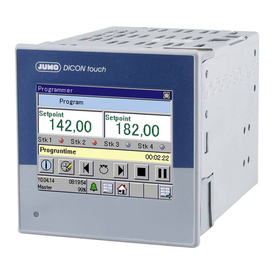
Two-channel process and program controller with paperless recorder and touchscreen
Hide thumbs
Also See for DICON touch:
- Operating manual (196 pages) ,
- Quick start manual (128 pages) ,
- Manual (60 pages)
Table of Contents
Advertisement
Quick Links
Download this manual
See also:
Operating Manual
Advertisement
Table of Contents

Related Manuals for JUMO DICON touch


Summary of Contents for JUMO DICON touch
- Page 1 JUMO DICON touch Two-channel process and program controller with with paperless recorder and touchscreen B 703571.2.0 Interface description Modbus 2015-05-01/00626448...
-
Page 3: Table Of Contents
Contents Safety information ..........7 Warning symbols . - Page 4 Contents Browser connection and web server ..........45 E-mail (SMTP and POP3) .
- Page 5 Contents 7.3.13 Timers ..............75 7.3.14 Analog and digital flag .
- Page 6 Contents...
-
Page 7: Safety Information
1 Safety information Warning symbols DANGER! This symbol indicates that personal injury caused by electrical shock may occur if the re- spective precautionary measures are not carried out. WARNING! This symbol in connection with the signal word indicates that personal injury may occur if the respective precautionary measures are not carried out. - Page 8 1 Safety information...
-
Page 9: Modbus Protocol Description
2 Modbus protocol description Master-slave principle Communication between a master (e.g. a SCADA system or PLC) and a device type 703571 as slave takes place on the basis of the master-slave principle in the form of a data query – response. -
Page 10: Transmission Media For Modbus
2 Modbus protocol description Transmission media for Modbus Serial interface For data communication via a serial interface, the Modbus specification provides the trans- mission modes RTU mode (Remote Terminal Unit) and ASCII mode (transmission of data in ASCII format). Device type 703571 supports the RTU mode only. Here, the data are transmit- ted via the serial bus in binary format (RS422/485). -
Page 11: Function Codes
2 Modbus protocol description Function codes Function overview The functions described in the following (from the Modbus Standard) are available for extract- ing measured values, device and process data, and for writing data. Function code Function Limit Hex. Dec. 03 or 04 3 or 4 Reading n words Max. -
Page 12: Reading N Words
2 Modbus protocol description 2.4.1 Reading n words This function is used to read n words, starting from a specific address. Data query Slave address Function code Address of Number of words Checksum CRC 0x03 or 0x04 first word 1 byte 1 byte 2 bytes 2 bytes... -
Page 13: Writing One Word
2 Modbus protocol description 2.4.2 Writing one word The data blocks for the data query and response are identical when writing a word. Data query Slave address Function code Word address Word value Checksum CRC 0x06 1 byte 1 byte 2 bytes 2 bytes 2 bytes... -
Page 14: Writing N Words
2 Modbus protocol description 2.4.3 Writing n words Data query Slave address Function Address of Number of Number of Word Checksum code first word words bytes value(s) 0x10 1 byte 1 byte 2 bytes 2 bytes 1 byte x bytes 2 bytes Response Slave address... -
Page 15: Data Types
2 Modbus protocol description Data types Data Description Access Possible Number type function codes Modbus register Byte Low byte of a word as an integer value; the high byte is not used read only 03, 04 Value ranges: read/write 03, 04, 06, 16 0 to 255 for unsigned data -127 to 127 for signed data Word... - Page 16 2 Modbus protocol description Data Description Access Possible Number type function codes Modbus register Uint32 2 words (4 bytes) as unsigned integer value read only 03, 04 Value range: 0 to 4,294,967,295 read/write 03, 04, 16 Char[60] Character string for up to 20 Unicode characters in UTF-8 coding read only 03, 04 with up to 3 bytes per character...
-
Page 17: Examples Of Data Transmission
2 Modbus protocol description Examples of data transmission The function 0x03 (reading) or 0x04 (writing one word) is used to extract integers, floating-point values, and text values. Data query Slave address Function code Address of Number of words Checksum CRC 0x03 or 0x04 first word 1 byte... -
Page 18: Floating-Point Values
2 Modbus protocol description 2.6.2 Floating-point values For floating-point values, device type 703571 operates using the IEEE 754 standard format (32-bit), but with the difference that bytes 1 and 2 are interchanged with bytes 3 and 4. Single-precision floating-point format (32-bit) acc. to IEEE 754 standard, "Float (LSB)" SEEEEEEE EMMMMMMM MMMMMMMM... -
Page 19: Character Strings (Texts)
2 Modbus protocol description After being transmitted from the device, the bytes for the floating-point value must be inter- changed accordingly. Many compilers (e.g. Microsoft Visual C++) store the floating-point val- ues in the following sequence: Floating-point value Address x Address x+1 Address x+2 Address x+3... - Page 20 2 Modbus protocol description TIP! The value (here: AA) before the CRC sum (here: C5 DF) is not considered, since it follows the terminating code "\0".
-
Page 21: Checksum (Crc16)
2 Modbus protocol description Checksum (CRC16) Calculation principle Transmission errors are detected with the aid of the checksum (CRC16). If an error is detected during evaluation, the device concerned does not respond. CRC = 0xFFFF CRC = CRC XOR BytesOfMessage For (1 to 8) CRC = SHR(CRC) if (flag shifted to the right = 1) -
Page 22: Error Messages
2 Modbus protocol description Error messages 2.8.1 Modbus error codes Requirements for Modbus communication The following conditions must be met for a slave to receive, process, and respond to queries: • Baud rate and/or data format of master and slave must match. •... -
Page 23: Error Messages For Invalid Values
2 Modbus protocol description 2.8.2 Error messages for invalid values For measured values in floating-point format, the error number itself is displayed in the value, i.e. instead of the measured value alone, the error number is returned as part of the value. Error code for Errors floating-point values... -
Page 24: Error Codes As Integer Return Values
2 Modbus protocol description 2.8.3 Error codes as integer return values For some longer processes (e.g. sending e-mail or active transmission of frames as Modbus master), an error code is entered in a result field or event list at the end. Chapter 7.3.18 "Modbus error", page 80 Error codes Error code... - Page 25 2 Modbus protocol description Error code Description Printer busy or not ready Setpoint value 1 not programmed Set up printer (config. / interface) Possible only when device in MANUAL mode Autotuning already running Time axis elapsed or not programmed Time axis cannot be copied Time axis does not exist Program change is locked MANUAL mode is locked...
- Page 26 2 Modbus protocol description Error code Description Error list: Flash memory processing Flash memory write error Error list: Other errors Undefined error Division by zero RAM memory location cannot be detected RTC runtime exceeded ID does not exist Index too large (overflow) Invalid data Invalid parameter String without 0 character...
- Page 27 2 Modbus protocol description Error code Description Unknown PAP code Ignored IPCP option Ignored IPCP code Unknown CHAP code IP checksum incorrect Unknown IP protocol Unknown ICMP type Unknown LCP type Received as client DNS query Unknown DNS error DNS response is split No IP received via DNS Unknown UDP port TCP checksum incorrect...
- Page 28 2 Modbus protocol description Error code Description Error uninstalling MFS file system...
-
Page 29: Interfaces
3 Interfaces Location of interfaces Device type 703571 features an interface RS485 (COM 1) as standard. It is designed for trans- mitting data using the Modbus protocol (slave or master) and for connecting an ER8 relay mod- ule. An RS422/485, PROFIBUS-DP, or Ethernet interface are also available for retrofitting in the COM 2 expansion slot. -
Page 30: Interfaces
3 Interfaces Interfaces 3.2.1 USB device, USB host, and COM 1 interfaces as standard Connection (Connec- Symbol and terminal designation tion ele- ment) USB device interface (21) USB host (20) COM 1 serial interface RS485 (13) 1 TxD+/RxD+ Transmission/received (galvanically isolated) data + 2 TxD-/RxD- Transmission/received... -
Page 31: Terminating Resistors
3 Interfaces TIP! A twisted connecting cable with shielding must be used to connect the RS422/485 interface; to the greatest extent possible, it should not be laid close to current-carrying components or cables and its shielding should be grounded on one side. To avoid transmission errors, only the signals listed above may be connected. -
Page 32: Configuring Interfaces
TIP! Changes to the configuration settings described in this chapter can be made directly on the device or by means of the JUMO PC setup program. TIP! Changing settings in the "Configuration" menu is possible only if a user is logged in with the appropriate user rights. - Page 33 3 Interfaces Settings for serial interfaces For all user devices on a bus to be able to communicate with one another, their interface set- tings must match. The table below shows the setting options for the serial interfaces on device type 703571.
- Page 34 Settings for Ethernet interface A patch/crossover cable with an RJ45 connector is required to use the Ethernet interface. The Ethernet interface can be configured directly on the device or with the aid of the JUMO PC set- up program. The following protocols can be used for communication over Ethernet: •...
- Page 35 3 Interfaces Configuration Selection/settings Description item Transfer rate Automatic Bit rate and duplex mode of the Ethernet optional 10 Mbit/s half duplex board 10 Mbit/s full duplex 100 Mbit/s half duplex This setting must match the setting of the switch 100 Mbit/s full duplex or router port to which device type 703571 is con- nected.
- Page 36 3 Interfaces...
-
Page 37: Modbus Via A Serial Interface
4 Modbus via a serial interface Modbus timing for serial interface RS422/485 Device type 703571 features a serial interface RS485 on COM 1 as standard. An RS422/485 can also be retrofitted on expansion slot COM 2. These interfaces can be used to connect the device to up to 2 bus systems. In each bus, one master can access several slaves that are accessible by means of unique device addresses. -
Page 38: Modbus Master Operation
4 Modbus via a serial interface Character transmission time The beginning and end of a data block are identified by pauses in transmission. The character transmission time (time to transmit one character) depends on the baud rate and the data for- mat used. - Page 39 4 Modbus via a serial interface regardless of whether a process value has changed or not. This rules out a transmission that depends on the condition of a change. The complete frame is always transmitted with the frame length configured in the setup program. TIP! Double writing of a target variable, e.g.
-
Page 40: Modbus Slave Operation
4 Modbus via a serial interface Modbus slave operation If device type 703571 has been configured as a slave, it responds to Modbus queries from the master on the network. The master controls the data exchange and the slaves only have a re- sponse function. -
Page 41: Modbus And Other Protocols Over Ethernet
5 Modbus and other protocols over Ethernet Modbus/TCP protocol Modbus/TCP uses the Ethernet interface for communicating with the Modbus data. The Mod- bus telegrams are transmitted via an Ethernet network (IEEE 802.3) using the TCP protocol of the TCP/IP protocol family. The device type 703571 can assume the role of the slave or master here too. - Page 42 5 Modbus and other protocols over Ethernet Example: Reading n words The time of the device is to be read. In this example, the address is 0x11E6 to 0x11E8. See also the Modbus example in Chapter 2.4.1 "Reading n words", page 12. Query: MBAP header Modbus telegram...
-
Page 43: Networking With Modbus/Tcp
5 Modbus and other protocols over Ethernet Networking with Modbus/TCP The image below provides an overview of the networking options when using the Modbus/TCP protocol: Each Modbus/TCP node is accessible via a unique IP address. The "Unit ID" also contained in the protocol (= device address) must be 0xFF for the node directly attached to the network. -
Page 44: Modbus Slave With Modbus/Tcp
5 Modbus and other protocols over Ethernet Chronological sequence The respective interface searches for all frames configured for it (setup program: > M > menu item I ) and cyclically ETUP ONLY ODBUS FRAMES FOR READING WRITING NTERFACE transmits them in sequence, in the example below to frame 1, frame 2, and frame 3. Frame 1 Frame 2 Frame 3... -
Page 45: Browser Connection And Web Server
5 Modbus and other protocols over Ethernet Browser connection and web server Device type 703571 can also be accessed by a browser using the HTTP protocol. The required URL for this is the IP address of device type 703571 (in the above example 192.168.0.100). The HTML start page "index.htm"... -
Page 46: E-Mail (Smtp And Pop3)
5 Modbus and other protocols over Ethernet E-mail (SMTP and POP3) Device type 703571 can send e-mails (e.g. alarms). In this case, it is the master (client) and can access SMTP servers at the standard port (25) as well as POP3 servers at the standard port (110). - Page 47 5 Modbus and other protocols over Ethernet Serves as a gateway between the local company network and the worldwide Internet. It is also used for the conversion of "local" IP addresses (used in the company network) to "one-time" IP addresses (used on the Internet).
- Page 48 5 Modbus and other protocols over Ethernet Sending an e-mail via the Internet Here, several steps depend on configured device parameters. An error code of the event entry (particularly the error codes 120 to 175) can suggest an incorrectly set parameter. An incorrect- ly entered IP address of the DNS server, for example, generates the error code 153 = "No IP received via DNS".
-
Page 49: User Frames
6 User frames General information Device type 703571 allows the user to individually compile Modbus frames for his application. This achieves a high level of flexibility and the user can thus reduce the data exchanged on the bus to the volume he requires. This provides a significant advantage with regard to the transmission speed. - Page 50 6 User frames TIP! When actively transmitting as a Modbus master, repetitive errors are entered in the event list. Corresponding error codes can be found in Chapter 2.8.3 "Error codes as integer return val- ues", page 24. Error monitoring Each frame is monitored for data transmission. If an error occurs, the corresponding error flag is set, an error code is also stored for each frame, and an entry is written in the event list.
-
Page 51: Compiling Modbus Frames
6 User frames Compiling Modbus frames The "Modbus frames for reading" and "Modbus frames for writing" options are found under > S in the setup program. ETUP NAME ETUP ONLY 6.3.1 Modbus frames for reading This function is used to compile up to eight Modbus frames for reading process values of ex- ternal devices (via interface) individually for each opposite end. - Page 52 6 User frames Parameter Selection/settings Description Interface The selection determines whether the frame is actively transmitted as a master or only available for queries as a slave. In the case of a Modbus master, the interface on which the relevant frame is used is also specified. If it is a LAN interface, the external device to be addressed must also be selected.
- Page 53 6 User frames Editing When the "Edit" button is clicked, this window appears: Parameters Parameter Selection/settings Description Variables Analog, digital, integer, and text variables Inactive No variable selected Select variable Selector for selecting a variable Data type The data type preset depends on the type of the external input in the setup pro- gram.
-
Page 54: Modbus Frames For Writing
6 User frames Parameter Selection/settings Description Factor Using the factor makes it possible to transmit floating-point values in the integer format. The transmitter multiplies the data with the corresponding factor before transmission. The data must be divided by the same value in the receiver. Complete floating-point value range This factor is used to rescale values dur- allowed;... - Page 55 6 User frames Parameters Parameter Selection/settings Description Comment Frame 1 Comment on the more detailed descrip- tion of the frame Use default text or edit text. Interface The selection determines whether the frame is actively transmitted as a master or only available for queries as a slave.
- Page 56 6 User frames Editing When the "Edit" button is clicked, this window appears: Parameters Parameter Selection/settings Description Process value Analog, digital, integer, and text selector selector Inactive No variable selected Select variable Selector for selecting a variable Data type The data type preset depends on the type of the process value in the setup pro- gram.
-
Page 57: Examples For The Data Transmission Options With Frames
6 User frames Parameter Selection/settings Description Factor Using the factor makes it possible to transmit floating-point values in the integer format. The transmitter multiplies the data with the corresponding factor before transmission. The data must be divided by the same value in the receiver. Complete floating-point value range This factor is used to rescale values dur- allowed;... - Page 58 6 User frames...
-
Page 59: Modbus Address Tables
7 Modbus address tables The tables in this chapter list all process and device data for device type 703571 with their Mod- bus address, the data type, and the possible access options (Modbus function codes). CAUTION! Write operations result in saving to the EEPROM or flash memory. These memory modules only have a limited number of write cycles (approx. -
Page 60: Configuration Data And Parameters
7 Modbus address tables Configuration data and parameters 7.2.1 Device software version Modbus address Signal designation Data type Access Hex. Dec. 0x000A 0010 Device software version LONG 7.2.2 Device name Modbus address Signal designation Data type Access Hex. Dec. 0x1000 4096 Device name The 1st and 2nd bytes of the character string consisting... -
Page 61: Ramp Slope, Controllers 1, 2
7 Modbus address tables 7.2.4 Ramp slope, controllers 1, 2 Modbus address Signal designation Data type Access Hex. Dec. 0x1091 4241 Ramp slope for positive gradient, controller 1 FLOAT 0x1093 4243 Ramp slope for negative gradient, controller 1 FLOAT 0x1095 4245 Ramp slope for positive gradient, controller 2 FLOAT... -
Page 62: Controller 1, Parameter Block 3
7 Modbus address tables Modbus address Signal designation Data type Access 0x10BB 4283 TV1 derivative time (D component) FLOAT 0x10BD 4385 TV2 derivative time (D component) FLOAT 0x10BF 4387 TN1 reset time (I component) FLOAT 0x10C1 4289 TN2 reset time (I component) FLOAT 0x10C3 4291 CY1 cycle time... -
Page 63: Controller 1, Parameter Block 4
7 Modbus address tables Modbus address Signal designation Data type Access Hex. Dec. 0x10F1 4337 TK2 minimum start time of the 2nd digital output FLOAT 7.2.8 Controller 1, parameter block 4 Modbus address Signal designation Data type Access Hex. Dec. 0x10F3 4339 XP1 proportional band (P component) -
Page 64: Controller 2, Parameter Block 2
7 Modbus address tables Modbus address Signal designation Data type Access Hex. Dec. 0x111F 4383 CY2 cycle time FLOAT 0x1121 4385 XSH switching hysteresis between 1st and 2nd digital FLOAT output 0x1123 4387 XD1 switching differential of the 1st digital output FLOAT 0x1125 4389... -
Page 65: Controller 2, Parameter Block 3
7 Modbus address tables 7.2.11 Controller 2, parameter block 3 Modbus address Signal designation Data type Access Hex. Dec. 0x114D 4429 XP1 proportional band (P component) FLOAT 0x114F 4431 XP2 proportional band (P component) FLOAT 0x1151 4433 TV1 derivative time (D component) FLOAT 0x1153 4435... -
Page 66: Setpoint Values, Controller 1
7 Modbus address tables Modbus address Signal designation Data type Access Hex. Dec. 0x117F 4479 XD2 switching differential of the 2nd digital output FLOAT 0x1181 4481 TT actuator time INT16 0x1182 4482 Y0 working point INT16 0x1183 4483 Y1 output value limit INT16 0x1184 4484... -
Page 67: Analog And Digital Flags 1 To 8
7 Modbus address tables Modbus address Signal designation Data type Access Hex. Dec. 0x11A5 4517 Offset, analog input IN10 FLOAT 0x11A7 4519 Offset, analog input IN11 FLOAT 7.2.16 Analog and digital flags 1 to 8 Modbus address Signal designation Data type Access Hex. -
Page 68: Process Values
7 Modbus address tables Process values 7.3.1 Transmission times of the frames Modbus address Signal designation Data type Access Hex. Dec. 0x017E Modbus master, COM 1: actual cycle time in 5 ms LONG ticks 0x0187 Modbus master, COM 2: actual cycle time in 5 ms LONG ticks 0x0194... -
Page 69: Controller 1
7 Modbus address tables 7.3.4 Controller 1 Modbus address Signal designation Data type Access Hex. Dec. 0x122D 4653 Actual value, controller 1 FLOAT 0x122F 4655 Setpoint value, controller 1 FLOAT 0x1231 4657 Output level, controller 1 FLOAT 0x1233 4659 Output level output 1, controller 1 FLOAT 0x1235 4661... -
Page 70: Setpoint Values, Controller 2
7 Modbus address tables Modbus address Signal designation Data type Access Hex. Dec. 0x1255 4693 Setpoint W3 FLOAT 0x1257 4695 Setpoint W4 FLOAT 0x1259 4697 Setpoint value, interface FLOAT 0x125B 4699 Setpoint limit WA (start) FLOAT 0x125D 4701 Setpoint limit WE (end) FLOAT 7.3.7 Setpoint values, controller 2... - Page 71 7 Modbus address tables Modbus address Signal designation Data type Access Hex. Dec. 0x1287 4743 Tolerance band MAX FLOAT 0x1289 4745 Program generator mode INT16 0=Basic status 1=Manual operating mode 2=Prerun 3=Program start 4=Automatic operation 6=Program end 0x128A 4746 Program generator automatic signal INT16 0x128B 4747...
-
Page 72: Math, Logic
7 Modbus address tables 7.3.9 Math, logic Modbus address Signal designation Data type Access Hex. Dec. 0x128F 4751 Math 1 FLOAT 0x1291 4753 Math 2 FLOAT 0x1293 4755 Math 3 FLOAT 0x1295 4757 Math 4 FLOAT 0x1297 4759 Math 5 FLOAT 0x1299 4761... -
Page 73: Digital Inputs 1 To 7 And Their Alarms
7 Modbus address tables Modbus address Signal designation Data type Access Hex. Dec. 0x12BA 4794 Logic alarm 4 BOOL 0x12BB 4795 Logic alarm 5 BOOL 0x12BC 4796 Logic alarm 6 BOOL 0x12BD 4797 Logic alarm 7 BOOL 0x12BE 4798 Logic alarm 8 BOOL 7.3.10 Digital inputs 1 to 7 and their alarms... -
Page 74: Digital Control Signals
7 Modbus address tables Modbus address Signal designation Data type Access Hex. Dec. 0x12D5 4821 Limit value output 7 BOOL 0x12D6 4822 Limit value output 8 BOOL 0x12D7 4823 Limit value output 9 BOOL 0x12D8 4824 Limit value output 10 BOOL 0x12D9 4825... -
Page 75: Timers
7 Modbus address tables Modbus address Signal designation Data type Access Hex. Dec. 0x12F5 4853 Digital control signal 7 BOOL 0x12F6 4854 Digital control signal 8 BOOL 0x12F7 4855 Digital control signal 1, alarm BOOL 0x12F8 4856 Digital control signal 2, alarm BOOL 0x12F9 4857... -
Page 76: Analog And Digital Flag
7 Modbus address tables 7.3.14 Analog and digital flag Modbus address Signal designation Data type Access Hex. Dec. 0x1327 4903 Analog flag 1 FLOAT 0x1329 4905 Analog flag 2 FLOAT 0x132B 4907 Analog flag 3 FLOAT 0x132D 4909 Analog flag 4 FLOAT 0x132F 4911... - Page 77 7 Modbus address tables Modbus address Signal designation Data type Hex. Dec. 0x135B 4955 Operation, program start BOOL 0x135C 4956 Operation, program stop BOOL 0x135D 4957 Operation, program break BOOL 0x135E 4958 Operation, manual program BOOL 0x135F 4959 Operation, fast forward BOOL 0x1360 4960...
-
Page 78: Outputs
7 Modbus address tables Modbus address Signal designation Data type Hex. Dec. 0x1387 4999 Operation, function key 2 BOOL 7.3.16 Outputs Modbus address Signal designation Data type Access Hex. Dec. 0x13B0 5040 Switching output 1 INT16 0x13B1 5041 Switching output 2 INT16 0x13B2 5042... - Page 79 7 Modbus address tables Modbus address Signal designation Data type Access Hex. Dec. 0x13D6 5078 External analog input 5 FLOAT 0x13D8 5080 External analog input 6 FLOAT 0x13DA 5082 External analog input 7 FLOAT 0x13DC 5084 External analog input 8 FLOAT 0x13DE 5086 External analog alarm, min.
-
Page 80: Modbus Error
7 Modbus address tables 7.3.18 Modbus error Modbus address Signal designation Data type Access Hex. Dec. 0x1532 5426 COM 1 error state Bool 0x1533 5427 COM 1 last error code Word 0x1534 5428 COM 2 error state Bool 0x1535 5429 COM 2 last error code Word 0x1536... -
Page 81: Program Editor Memory
7 Modbus address tables 7.3.21 Program editor memory Modbus address Signal designation Data type Access Hex. Dec. 0x4000 16384 Function INT16 6=Delete program (0x86) 11=Read program (0x8B) 12=Write program (0x8C) 0x4002 16386 Error INT16 0x4003 16387 Number of sections 1 to 50 INT16 0x4004 16388... -
Page 82: Program Name
7 Modbus address tables Modbus address Signal designation Data type Access Hex. Dec. Calculation formula: Address section no.(n) = 4006Hex + (n-1 Dec.)*10Hex Address section no.(50) = 4006Hex + (31 Hex)*10Hex.= 4006Hex+310Hex= 4316 Hex Section 50: Has an address offset of (31 Hex)*(10 Hex) = 310 Hex 0x4316 17174 Setpoint W1... -
Page 83: Compiled Writing Frames
7 Modbus address tables 7.3.25 Compiled writing frames Modbus address Signal designation Data type Access Hex. Dec. 0x8800 34816 Write Frame 1 Byte[254] 0x8880 34944 Write Frame 2 Byte[254] 0x8900 35072 Write Frame 3 Byte[254] 0x8980 35200 Write Frame 4 Byte[254] 0x8A00 35328... - Page 84 7 Modbus address tables...
- Page 86 JUMO GmbH & Co. KG Street address: Moritz-Juchheim-Straße 1 36039 Fulda, Germany Delivery address: Mackenrodtstraße 14 36039 Fulda, Germany Postal address: 36035 Fulda, Germany Phone: +49 661 6003-0 Fax: +49 661 6003-607 E-mail: mail@jumo.net Internet: www.jumo.net JUMO Instrument Co. Ltd.
Need help?
Do you have a question about the DICON touch and is the answer not in the manual?
Questions and answers