JUMO DICON touch Manual
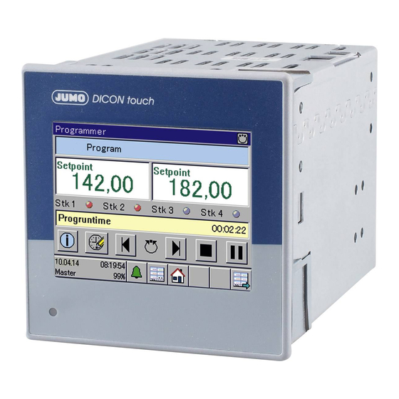
Two-channel process and program controller with paperless recorder and touchscreen 8.9 cm 3.5"
Hide thumbs
Also See for DICON touch:
- Operating manual (196 pages) ,
- Quick start manual (128 pages) ,
- Interface manual (86 pages)

Related Manuals for JUMO DICON touch


Summary of Contents for JUMO DICON touch
- Page 1 JUMO DICON touch Two-channel process and program controller with paperless recorder and touchscreen 8.9 cm (3.5") 70357107T92Z001K000 V6.00/EN/00661200/2020-01-29...
-
Page 3: Table Of Contents
Project integration of JUMO IO devices ........ - Page 4 Contents...
-
Page 5: Safety Information
Safety information 1 Safety information Warning symbols DANGER! This symbol indicates that personal injury from electrocution may occur if the appropriate precaution- ary measures are not taken. WARNING! This symbol in connection with the signal word indicates that personal injury may occur if the respective precautionary measures are not carried out. - Page 6 1 Safety information...
-
Page 7: Compatibility And System Requirements
The certificate for the JUMO DICON touch is available for download from the product page on the Inter- net. The following QR code or web address will take you to the product page of the JUMO DICON touch: qr-703571-en.jumo.info PROFINET IO and Ethernet standard services The PROFINET interface supports all Ethernet standard services. - Page 8 2 Compatibility and system requirements The information can be displayed and reviewed with the aid of the device menu. Display device software version: Device menu > Device info > General > Version > SW version Display hardware compatibility index: Device menu > Device info > General > Version > HW compatibility index...
-
Page 9: Electrical Connection
(3) free Ethernet port (e.g. for additional PROFINET IO devices) NOTE! The cyclical data exchange with JUMO PROFINET IO devices is based on the RT protocol (Confor- mance Class B). PROFINET RT communication cannot be routed. It is thus necessary that the PROF- INET IO controller and the IO devices be in a common broadcast domain (not connected via a router). - Page 10 3 Electrical connection...
-
Page 11: The Gsdml File
IO controller, the modules to be transferred via the PROFINET-IO have to be as- signed to the free slots of the JUMO IO device in the project structure of the IO controller. The IO items of the inserted modules are then available for the programming of the IO controller. The assignment of the JUMO field device data to the IO items of the individual modules is provided for the programmer in the printed module configuration list. - Page 12 Bit item Bit ad- Explanation dress Sub-module 1 Status bits 1 USINT Collective alarm Internal signals of the JUMO DICON touch Collective alarm ac- knowledged See operating manual, chapter on digital Memory alarm selector configuration Pre-alarm battery Battery empty...
- Page 13 IO item Type Bit item Bit ad- Explanation dress Encoder status USINT – Internal signals of the JUMO DICON touch Programstopsignal Basic status See operating manual, chapter on digital Pre-programming selector configuration Manual operation mode 4 Programautosignal Program end signal...
- Page 14 IO item Type Bit item Bit ad- Explanation dress Current program UINT – – Internal signals of the JUMO DICON touch number Current section num- UINT – – See operating manual, chapter on integer selector configuration Current program run- UDINT –...
- Page 15 Bit item Bit ad- Explanation dress Binary values UDINT Digital input IN1 Internal signals of the JUMO DICON touch Digital input IN2 Digital input IN3 See operating manual, chapter on digital Digital input IN4 selector configuration Digital input IN5...
- Page 16 The configurable modules are intended exclusively for transferring cyclical IO data. The assignment of the modules can be compiled and printed via the JUMO PC setup program of the DICON touch. The printed list will help you maintain an overview of the configured modules of the JUMO IO device during the project planning and programming of the IO controller (PLC, host PC or similar).
- Page 17 4 The GSDML file Module types IO items Data type Data direction IO controller Analog input values Analog values 1 to 16, REAL read Digital input values Digital values 1 to 32 BOOL read Integer input values Integers 1 to 8 DINT read Analog output values...
- Page 18 4 The GSDML file...
-
Page 19: Noncyclical Data Exchange
CAUTION! All temperature values of the JUMO IO device are transferred in the unit "°C". Misinterpretation of measured values of a JUMO IO device in the IO controller can cause errors in the system control. Note the unit for the transferred temperature values! - Page 20 Waiting time 0.5 to 2 s RDREC.request Transfer of the data exchange packet RDREC.BUSY = TRUE with response data from the IO device to the IO controller JUMO IO device Unpacking and Transfer of processing of the RDREC.response response data:...
-
Page 21: Single-Id And Multi-Id
5 Noncyclical data exchange 5.1.1 Single-ID and Multi-ID To implement the exchange of single (Single-ID) or multiple (Multi-ID) noncyclical data points, you must take the following steps: • Declare 1 data structure each for both the outgoing and the incoming direction. Select the "Single- ID"... - Page 22 „DIR“ ist die Data direction for transferring noncyclical data. The data direction must be specified by the PLC programmer in the data exchange packet of the query from the IO controller Incoming: and controls the processing of the data in the JUMO IO device ERROR accordingly. Coding:...
- Page 23 The "ID-PLC" value must be used by the IO controller for se- quentially numbering the outgoing data exchange packets. JUMO IO devices enter the same number in the ID-PLC in the data exchange packet of the ensuing response, so that re-...
- Page 24 IO con- troller. The "DIR" variables control the process- Any basic data type with a VALUE_1 ing of the single data points in the JUMO IO length of 32 bits device accordingly. Query/re-...
- Page 25 PROFINET IO function blocks. Instead, data exchange packets that are processed by the IO device are transferred. The IO controller has to write a data exchange packet with query data to the JUMO IO device (WRREC). JUMO IO devices accept the data from the data exchange packet and then prepare this pack- et with response data for the IO controller.
-
Page 26: Programs For Program Controllers
JUMO IO device. The data have to be copied from here to the target before they are overwritten by another read request. - Page 27 5 Noncyclical data exchange To implement the exchange of program memories, you must take the following steps: • Declare 1 data structure in the "Program data transfer" format (partial data records of a program memory to be transferred) for both the outgoing and the incoming direction. •...
- Page 28 5 Noncyclical data exchange Declaration of data structures for the transfer of program memories In the IO controller, you need to declare 1 data structure (user-defined "STRUCT variable") in the "Pro- gram data transfer" format as both the target and the source memory for all data exchange packets for incoming and outgoing transfer direction, and one data structure for provisioning and one for accepting all data of a program memory during the data exchange sequence in the "editing memory"...
- Page 29 For more details about the individual data of a USINT Number of repeti- program section, see the operating manual for tions the JUMO DICON touch. USINT Start section The dummy variables are strictly fill bytes. They USINT Parameter block...
- Page 30 The last byte (array element 72) contains the 1- byte long character for the end code (NULL). Icon: The "Icon" variable determines the selec- tion of one of the icons in the JUMO IO device for visualizing the program profile on the JUMO IO device display.
- Page 31 Data direction for transferring noncyclical data The data direction must be specified by the PLC programmer in the data exchange packet of the query from the IO controller and controls the processing of the data in the JUMO IO device accordingly. Coding:...
- Page 32 Name Explanation BYTE ErrorCode In case of an error, the JUMO IO device enters into this variable error messages, which can be evaluated by the IO controller. Value = 0: No error Value = 1: Program does not exist BYTE Dummy Fill byte (no function;...
- Page 33 PROFINET IO function blocks. Instead, data exchange packets that are processed by the IO device are transferred. The IO controller has to write a data exchange packet with query data to the JUMO IO device (WRREC). JUMO IO devices accept the data from the data exchange packet and then prepare this pack- et with response data for the IO controller.
- Page 34 JUMO IO device. The data have to be copied from here to the target before they are overwritten by another read request.
- Page 35 (Length of the data to be written for WRREC in bytes) MLEN (Maximum length of the data to be read for RDREC in bytes) Hardware detection of Slot 1 on JUMO IO devices (DeviceSta- tusBlock) (Hardware detection of slots/subslots to be addressed on the IO device) INDEX...
-
Page 36: Data Tables Of Noncyclical Data
CAUTION! All temperature values of the JUMO IO device are transferred in the unit "°C". Misinterpretation of measured values of a JUMO IO device in the IO controller can cause errors in the system control. Note the unit for the transferred temperature values! 5.2.1... - Page 37 5 Noncyclical data exchange Controller 1 parameter block 1 Index Signal designation Data type Access XP1 proportional band (P component) REAL Read/Write XP2 proportional band (P component) REAL Read/Write TV1 derivative time (D component) REAL Read/Write TV2 derivative time (D component) REAL Read/Write TN1 reset time (I component)
- Page 38 5 Noncyclical data exchange Controller 1 parameter block 3 Index Signal designation Data type Access XP1 proportional band (P component) REAL Read/Write XP2 proportional band (P component) REAL Read/Write TV1 derivative time (D component) REAL Read/Write TV2 derivative time (D component) REAL Read/Write TN1 reset time (I component)
- Page 39 5 Noncyclical data exchange Controller 2 parameter block 1 Index Signal designation Data type Access XP1 proportional band (P component) REAL Read/Write XP2 proportional band (P component) REAL Read/Write TV1 derivative time (D component) REAL Read/Write TV2 derivative time (D component) REAL Read/Write TN1 reset time (I component)
- Page 40 5 Noncyclical data exchange Controller 2 parameter block 3 Index Signal designation Data type Access XP1 proportional band (P component) REAL Read/Write XP2 proportional band (P component) REAL Read/Write TV1 derivative time (D component) REAL Read/Write TV2 derivative time (D component) REAL Read/Write TN1 reset time (I component)
- Page 41 5 Noncyclical data exchange Index Signal designation Data type Access Setpoint W3 (controller 1) REAL Read/Write Setpoint W4 (controller 1) REAL Read/Write Setpoint values, controller 2 Index Signal designation Data type Access Setpoint W1 (controller 2) REAL Read/Write Setpoint W2 (controller 2) REAL Read/Write Setpoint W3 (controller 2)
-
Page 42: Process Values
5 Noncyclical data exchange 5.2.2 Process values Setpoint values Index Signal designation Data type Access Setpoint value, interface REAL Read Setpoint value, interface REAL Read Device operation Index Signal designation Data type Access Operation, tune start, controller 1 BOOL Read Operation, tune stop, controller 1 BOOL Read... - Page 43 5 Noncyclical data exchange Index Signal designation Data type Access Operation, timer start T2 BOOL Read Operation, timer stop T2 BOOL Read Operation, timer hold T2 BOOL Read Operation, timer acknowledgement T2 BOOL Read Operation, timer restart T2 BOOL Read Operation, hold, ramp 1 BOOL Read...
- Page 44 5 Noncyclical data exchange...
-
Page 45: Project Planning
Project integration of JUMO IO devices For JUMO field devices to be integrated into the project structure of the IO controller as IO device, the GSDML file of the respective device must be imported into the engineering system of your IO controller. -
Page 46: Configuring Profinet Modules
JUMO field device with all IO data, which the field devices provisions for the PROFINET IO communication. In the engineering system, the modules must then be assigned to the slots in the JUMO IO device, so that they can be queried by the IO controller during the cyclical communication. - Page 47 6 Project planning Procedure for module configuration 1. Call up the module configuration dialog in the JUMO PC setup program: Double-click on: Setup only > PROFINET configuration 2. In the "App text" and "App Version" fields of the module configuration dialog, assign information about the application (e.g.
- Page 48 6 Project planning 3. The module configuration contains 1 tab for each activated module. Define the number of modules you want to configure. To add modules, press the "Slot +" button. To reduce the number of modules, click on the next module tab to activate it and press the "Slot -" button. 4.
- Page 49 6. Once you have completed the configuration for all the required modules, click the "OK" button in the module configuration window to confirm the configuration. 7. Transfer the configuration to the JUMO field device and save the configuration file on the PC if re- quired.
-
Page 50: Configuring The Jumo Io Device
JUMO IO devices communicate with your PROFINET optional board via the internal Ethernet interface of the device. In order for the PROFINET optional board in a JUMO IO device to become operational, internal communication must be established between the optional board and the device. This requires valid IP configuration of the Ethernet interface of the JUMO IO device. - Page 51 Block diagram of a PROFINET optional board with its interfaces (4) (5) (1) Ethernet slot in a JUMO IO device (COM2) with its own MAC address (cf. chapter 6.3.3 "Device in- formation", Page 53) (2) Internal interface (SMK socket) of the PROFINET optional board for the slot in the JUMO IO device with its own MAC address (PROFINET MAC address of the JUMO IO device, cf.
- Page 52 Send clock and reduction ratio determine the frequency at which an IO device transfers cyclical data in a PROFINET IO network. The transfer cycle time of the JUMO IO device is calculated by dividing the send clock by the reduction ratio. On JUMO field devices, these parameters apply globally for all slots.
-
Page 53: Device Information
Open the Ethernet configuration: Device Menu > Configuration > Ethernet 3. After a valid IP configuration has been saved in the JUMO IO device, the PROFINET IO interface connects to the JUMO IO device and is initialized. To test, check the following indicators: The front status LED on the PROFINET optional board must glow green and the MAC addresses of the PROFINET optional board must now have valid content (not 00-00-00-00-00-00). - Page 54 6 Project planning Status: Data for connecting the JUMO IO device to the IO controller In addition to the essential IP configuration data for the JUMO IO device, additional important information is dis- played. For example: The "App Version" from the module configuration of the device (see chapter 6.2 "Configuring...
- Page 55 JUMO IO device via the Ethernet interface (COM2 slot). It is essential for communication that the Ethernet interface of the JUMO IO device be configured with a valid IP address (cf. chapter 6.3.2 "Communication parameters", Page 50). For checking and for diag- nostic purposes, the IP configuration of the Ethernet interface can be viewed in Device info.
- Page 56 6 Project planning...
-
Page 57: Error Messages
Error messages 7 Error messages Error messages for invalid values For measured values in float format, the error number itself is displayed as a value, i.e. instead of the measured value, the error number is returned. Error code for Error float values 1.0 ×... - Page 58 7 Error messages...
- Page 60 JUMO GmbH & Co. KG JUMO Instrument Co. Ltd. JUMO Process Control, Inc. Street address: JUMO House 6733 Myers Road Moritz-Juchheim-Straße 1 Temple Bank, Riverway East Syracuse, NY 13057, USA 36039 Fulda, Germany Harlow, Essex, CM20 2DY, UK Delivery address:...
Need help?
Do you have a question about the DICON touch and is the answer not in the manual?
Questions and answers