
Related Manuals for JUMO B 703571.0


Summary of Contents for JUMO B 703571.0
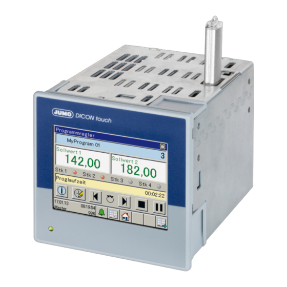
- Page 1 JUMO DICON touch Two-channel process and program controller with touchscreen 8.9 cm (3.5 ") B 703571.0 Operating Manual 2014-01-20/00603327...
-
Page 3: Table Of Contents
Introduction ............9 Safety information . - Page 4 Display and operating concept ..........35 Device menu .
- Page 5 Functional level ..........55 10.1 General information .
- Page 6 12.11 Recording ..............113 12.11.1Parameter .
- Page 7 13.11.3Signal types for process screens (overview) ........133 13.11.4General object features .
-
Page 9: Introduction
1 Introduction Safety information General information This manual contains information that must be observed in the interest of your own safety and to avoid damage to assets. This information is supported by symbols which are used in this manual as indicated. Please read this manual before commissioning the device. -
Page 10: Representation
1 Introduction & FURTHER INFORMATION! This symbol is used in the tables and refers to further information in connection with the table. DISPOSAL! This device and the batteries (if installed) must not be disposed in the garbage can after use! Please ensure that they are disposed properly and in an environmentally friendly manner. -
Page 11: Description
The device is easy to operate via a touchscreen. Both control channels use the tried-and-tested JUMO control algorithm with two possible opti- mization options. These enable a simple and highly-accurate startup. It also enables multiple zone control, cascade control, or other complex control tasks. -
Page 12: Block Diagram
1 Introduction Block diagram Relay output OUT1 Digital inputs In1 to 7 (changeover contact) (potential free contact) Relay output OUT2 Analog input ( universal) (changeover contact) Analog input (universal) In9 Digital/analog outputs OUT3 OUT4 Analog input (universal) In10 Digital/analog outputs OUT5 Analog input (universal) In11 OUT6... -
Page 13: Identifying The Device Version
2 Identifying the device version... -
Page 14: Order Details
2 Identifying the device version Order details Basic type 703571 JUMO DICON touch - two-channel process and program controller with RS485 inter- face Version Standard with factory settings Customer-specific configuration (specifications in plain text) National language of display texts German... - Page 15 2 Identifying the device version 1 solid-state relay 230 V, 1 A 1 logic output 0/22 V 2 logic outputs 0/12 V, 20 mA 1 analog output 2 PhotoMOS® relays Output 6 (OUT9/10) None 1 relay (changeover contact) 2 relays (N/O contact) 1 solid-state relay 230 V, 1 A 1 logic output 0/22 V 2 logic outputs 0/12 V, 20 mA...
-
Page 16: Scope Of Delivery
X - X List extra codes in sequence, separated by commas. Scope of delivery • 1 controller in the ordered version • 1 Operating Manual B 703571.0 • 1 panel seal 4 retaining elements for panel installation General accessories Article Part no. -
Page 17: Accessories
2 Identifying the device version Accessories Article Part no. Modules for expansion slots: 1 analog input (universal) 00581159 1 relay output (changeover contact) 00581160 2 relay outputs (N/O contact) 00581162 1 logic output DC 0/22 V max. 30 mA 00581165 2 logic outputs DC 0/12 V max. -
Page 18: Nameplate
The device type also contains information about optional default modules, as in the following example of the Ethernet interface (Figure 08): 703571/8-01-00-00-00-00-00-00-00-25-08... (see type key) Further information on identifying optional modules is included in this chapter: B 703571.0 - Chapter 9.2 "Slots", page 51... -
Page 19: Mounting
3 Mounting Mounting site and climatic conditions The mounting site should be free from vibration, dust and corrosive media. Install controllers as far away as possible from sources of electromagnetic fields, such as those created by fre- quency converters or high-voltage ignition transformers. Conditions at the mounting site must correspond to the following environmental influences: 3.1.1 Environmental influences... -
Page 20: Electrical Data
3 Mounting 3.1.3 Electrical data Voltage supply At the back via screw terminals Connection AC/DC 20 ... 30 V, 48 to 63 Hz or AC 110 to 240 V +10/-15 %, 48 to Voltage 63 Hz Power consumption At voltage supply 230 V: max. 38.1 VA/11.5 W At voltage supply 24 V: max. -
Page 21: Dimensions
3 Mounting Dimensions Panel thickness 130.9 - panel thickness +0.8 (22) (20) (21) (20) USB host interface (21) USB device interface for setup (22) Panel cut-out Close mounting If several devices are mounted on a switch board above or next to each other, the panel cut- outs must be positioned 35 mm horizontally and at least 80 mm vertically away from each oth-... -
Page 22: Insertion In Panel Cut-Out
3 Mounting Insertion in panel cut-out Step Activity Affix delivered panel seal (1) on the device from the rear Insert the device into the panel cut-out from the front and ensure the panel seal is correctly positioned so that no water or dirt can penetrate the case. From the panel rear, slide the mounting brackets into the guides on the sides of the case. - Page 23 3 Mounting CAUTION! Sharp tools can scratch and damage the cover. The front plate is not resistant to corrosive acids or lyes, abrasives, or cleaning with high- pressure cleaners. Do not use sharp objects near the device.
- Page 24 3 Mounting...
-
Page 25: Electrical Connection
4 Electrical connection Installation notes CAUTION! The delivery status of the device at the first startup does not necessarily correspond to the intended application (for example, Controller 2 inactive). This may result in undefined plant behavior. Therefore, where possible during startup, no actuators should be connected and load cur- rent circuits should be isolated. -
Page 26: Galvanic Isolation
4 Electrical connection Galvanic isolation Analog output Analog input IN8 AC 30 V AC 30 V DC 50 V DC 50 V Relay outputs Analog input IN11 AC 30 V AC 3600 V DC 50 V 2 PhotoMOS® solid state relay Digital input = DC 50 V, I... -
Page 27: Connection Diagram
4 Electrical connection Connection diagram DANGER! Works involving dangerous electrical voltage (230 V) are performed here. There is a risk of electric shock. Switch off all voltage circuits before routing. The electrical connection must only be carried out by qualified personnel. 4.3.1 Connection elements Analog input IN8... -
Page 28: Analog Inputs
4 Electrical connection 4.3.2 Analog inputs Input IN8, IN9 as standard Two analog inputs can be added to input (IN10), (IN11) optional boards Connection (Connection ele- Symbol and terminal designation ment) Input Thermocouple (1) IN8 (2) IN9 (3) IN10 (4) IN11 RTD temperature probe Two-wire circuit RTD temperature probe... -
Page 29: Analog Outputs
4 Electrical connection 4.3.3 Analog outputs One analog output can be added to output OUT 3/4 to 11/12 using optional boards Connection (Connection ele- Symbol and terminal designation ment) Input One analog output (8) OUT3/4 DC 0/2 to 10 V or DC 0/ (9) OUT5/6 4 to 20 mA (10) OUT7/8... - Page 30 4 Electrical connection Outputs OUT 3/4 to 11/12 can be extended using the following optional boards Connection (Connection Symbol and terminal designation element) Output 1 relay output (changeover (8) OUT3/4 contact) (9) OUT5/6 (10) OUT7/8 (11) OUT9/10 (12) OUT11/12 2 relay outputs (N/O contact) 1 solid state relay AC 230 V, 1 A 1 logic output...
- Page 31 4 Electrical connection Connection (Connection Symbol and terminal designation element) Output Two solid state relays AC 230 V, 1 A (for controlling the left and right-hand motor actuators, galvanically isolated) Combining a mains voltage circuit with a protective low-voltage circuit on a 2-way normally open contact option is not admissible.
-
Page 32: Voltage Supply (According To Nameplate)
4 Electrical connection 4.3.7 Voltage supply (according to nameplate) AC 230V (DC 24V) Connection (Connection ele- Symbol and terminal designation ment) Protection conductor Neutral conductor N (L-) Line conductor L1(L+) 4.3.8 Interfaces USB device, USB host and COM1 interfaces as standard Connection (Connection Symbol and terminal designation... - Page 33 4 Electrical connection COM2 interface can be expanded using optional boards Connection (Connection Symbol and terminal designation element) Ethernet (14) 1 TX+ Transmission data + 2 TX- Transmission data - 3 RX+ Received data + 6 RX- Received data - Serial interface RS422 1 RxD+ Received data +...
- Page 34 4 Electrical connection...
-
Page 35: Operation
5 Operation Display and operating concept The DICON touch is operated via a resistive touchscreen and also reacts to finger pressure. Commercially available pens with plastic tips can also be used. (Factory setting: switched off) actory setting: switched off Only available with option 223 Data recording and evaluation only available with option 2 function keys... -
Page 36: Alarm And Event List
All the functions in the device menu are described in the following sections of the B703571.0de operating manual. Chapter 6 "Login", page 43 B 703571.0 - Chapter 7 "User level (Log-In)", page 45 Chapter 8 "Program administration", page 47 B 703571.0 - Chapter 10 "Functional level", page 55 B 703571.0 - Chapter 11 "Parameterization", page 57... -
Page 37: Images In The Operating Loop
For the screen settings see B 703571.0 - Chapter 12.10 "Screen", page 106 To view the images displayed see B 703571.0 - Chapter 12.10.4 "Operating loop", page 108 5.5.1 Controller screen 1, Controller screen 2 and Controller overview You can change the color of these screens in the setup program. - Page 38 You can now manually influence the output level (by hand) Exit manual mode By touching the screen below the hand, you can exit manual mode and return to normal con- troller operation. Self-optimization B 703571.0- Chapter 12.6.3 "Self-optimization controller", page 82...
-
Page 39: Program Controller
Start/stop manual mode (for program controller) Manual mode is performed exactly as for a fixed-setpoint controller. Chapter 5.5.1 "Controller screen 1, Controller screen 2 and Controller overview", page 37 Self-optimization B 703571.0- Chapter 12.6.3 "Self-optimization controller", page 82... -
Page 40: General Screen 1.2
General screen 1.2 default Two general screens are available that do not contain any variables. The variables displayed can be configured. B 703571.0- Chapter 12.10.8 "General screens 1, 2", page 112 5.5.4 Recording image default Here the device is displaying up to four analog and three digital channels, like a line recorder. -
Page 41: Process Screen
This screen can be freely configured and is empty by default. A background image of your plant can be stored and animated with all the process values for the device. The setup program is required to design the graphics. B 703571.0 - Chapter 13.11 "Process screen", page 129... - Page 42 5 Operation...
-
Page 43: Login
6 Login Some of the levels in the device menu are username- and password-protected. The level pro- tection is defined in the user list by the setup program, using five different users. On entering the password, each user is entitled to use the "rights" available. If permitted, the rights and passwords can also be changed on the device. -
Page 44: Logging On
6 Login Logging on This sequence shows the logon process as the master user (with the default password 9200): User 1 is now logged on and is permitted to access all functions listed under "Rights". Logging out As soon as you are logged on, the Log-Out button is no longer grayed out and touching it will enable you to log out. -
Page 45: User Level (Log-In)
7 User level (Log-In) NOTE! This level is empty by default and parameters can only be defined using the setup program to appear in the device. Up to 25 parameters of any type from the configuration or parameter level can be included in this level. - Page 46 7 User level (Log-In) Device display Once the setup data has been transferred to the device, the setpoint values can be entered on the device.
-
Page 47: Program Administration
8 Program administration Enter program curves Ten programs can be entered on the device or in the setup program. 8.1.1 On the device Step Activity Enter program names and icons Enter first section: If the program memory is empty, the section will be highlighted in red. Each section consists of: target values 1 and 2, section time, control contacts, tolerance band, number of repetitions from start section, and parameter block. -
Page 48: About The Setup Program
8 Program administration 8.1.2 About the setup program Step Activity Start the setup program and click on Program editor > Program administration in the menu Enter sections in the table The table is displayed as a graphic with the program simulation... -
Page 49: Section Run Time
8 Program administration Step Activity Save the setup file and transfer the setup data to the device If a green icon (smiley) appears, then the programs have been successfully transferred. Two program curves are now saved in the device and can be started at any section at an adjustable time and run in parallel. -
Page 50: Tolerance Band
8 Program administration 8.1.6 Tolerance band B 703571.0 - Chapter 12.6.7 "Ramp function", page 95 8.1.7 Number of repetitions The number of repetitions is entered for a specific start section. 8.1.8 Start section Repetition begins from this section. Example 8.1.9... -
Page 51: Device Information
9 Device information The device information function enables hardware and software modules to be displayed. General information The type extra codes enabled in the device are displayed next to the device names. 9.1.1 Version, motherboard, Ethernet information Software version, fabrication number, and testing ID are displayed. Displays the hardware on the motherboard. -
Page 52: Digital And Analog Inputs, Digital And Analog Outputs, External Digital, And External Analog Inputs
9 Device information 9.3.1 Digital and analog inputs, digital and analog outputs, external digital, and external analog inputs Functions 9.4.1 Mathematics, logic signal, limit value outputs... -
Page 53: Timer Signal, Digital Controller Signals, Control Contacts, Controller, Analog Flag, Digital Flag
9 Device information 9.4.2 Timer signal, digital controller signals, control contacts, controller, analog flag, digital flag Status 9.5.1 Ethernet status 1 to 9... - Page 54 9 Device information...
-
Page 55: Functional Level
10 Functional level 10.1 General information NOTE! The functional level is faded out by default and must be activated using the setup program. 10.1.1 Activate functional level The functional level is activated in the screen menu and subsequently appears in the device menu. - Page 56 10 Functional level...
-
Page 57: Parameterization
11 Parameterization NOTE! The parameters described in this section can be entered either in the setup program or in DI- CON touch. This is where the parameters that are directly linked to the alignment of the con- troller with the control path are set, after the system has been commissioned. You must be logged in to change the parameters. -
Page 58: Controller/Parameter Blocks
Parameters that appear in pairs such as Proportional band 1 and 2 refer to the first and second controller outputs (for instance, with three-state controllers). The parameter blocks are assigned to both controllers in the configuration level. B 703571.0 - Chapter 12.6.2 "Controller inputs", page 80... - Page 59 11 Parameterization Parameter Setting Description Proportional band 0 ... 9999 Value for the proportional band The controller structure has no effect if (Xp1) Xp = 0 (behavior identical to limit value monitoring)! Proportional band 0 ... 9999 For a continuous controller, Xp must be >...
- Page 60 11 Parameterization Parameter Setting Description Min. output level -100 to +100 % Admissible minimum output level (only effective if Xp > 0) limit (Y2) Minimum relay 0 to 60 s Limits the frequency of switching for ON period 1 switched outputs (Tk1) Minimum relay 0 to 60 s...
- Page 61 11 Parameterization Transmission behavior The transmission behavior (controller structure) is determined by the configuration of the pa- rameters for the proportion band (P component), derivative time (D component), and reset time (I component). Two-state controller This controller has a switched output and can be parameterized with P, PI, PD, or PID trans- mission behavior.
-
Page 62: Setpoint Values
11 Parameterization Three-state controller This controller has two outputs, which can be configured as continuous (analog output) or switched (digital output). In both cases, the controller can be parameterized with P, PI, PD, or PID transmission behavior. The proportional bands Xp1 and Xp2 must be greater than 0 for the controller structure to take effect. -
Page 63: Entered On The Device
11 Parameterization Type Signal 2 (Bit 1) Signal 1 (Bit 0) Setpoint value, Setpoint value, setpoint setpoint Controller 1 Controller 2 changeover changeover Fixed-setpoint Setpoint value 1 Setpoint 1 controller Setpoint value 2 Setpoint value 2 Setpoint value 3 Setpoint value 3 Setpoint value 4 Setpoint value 4 Program control-... - Page 64 11 Parameterization...
-
Page 65: Configuration
12 Configuration NOTE! The parameters described in this section can be edited using either the setup program or DI- CON touch. The settings (for example, measured value recording, outputs, Ethernet, and con- troller type) that are required immediately for commissioning in a specific plant and therefore that seldom need to be changed, are set here. - Page 66 12 Configuration Category Signal Type Description Setpoint values Ramp end value, Controller 1 Internal Setpoint value for controller channel 1 to 2 Setpoint specification, Controller 1 as fixed setpoint controller Setpoint value 1 to 4, Controller 1 Siehe 9312.6.6Controller set- Ramp end value, Controller 2 point values Setpoint specification, Controller 2...
- Page 67 12 Configuration Category Signal Type Description Digital inputs Digital input 1 to 7 Internal Logic level for connected floating contacts 1 to 7 Siehe 7212.4Digital inputs IN1 to 7 External External digital input 1 to 8 External Logic level for the external digital digital inputs inputs 1 to 8 ...
- Page 68 12 Configuration Category Signal Type Description Function buttons Function button 1 to 2 Internal Logic level of the two function buttons Siehe 355.1Display and oper- ating concept Analog input MinAlarm IN8 Internal Min and max alarm signals of the alarm analog inputs 1 to 4 MaxAlarm IN8...
- Page 69 12 Configuration Category Signal Type Description Digital alarms Digital alarm 1 to 7 Internal Alarms for connected floating contacts 1 to 7 Siehe 7212.4Digital inputs IN1 to 7 Ext. digital Ext. digital alarm 1 to 8 External Alarms for ext. digital inputs alarms ...
-
Page 70: Basic Settings
12 Configuration 12.3 Basic settings The settings are applicable for the entire device. Setup dialog Parameter Parameter Selection/settings Description Device name Name 20 characters of editable text Language 1.German 2.English The device can save up to two languages. Additional languages can only be added using the setup program: E >... - Page 71 12 Configuration Parameter Selection/settings Description Online version vis. Standard online visualization Software version of the webserver soft- (only setup) ware No online visualization Example 333.01.01-13 If relevant, additional versions are listed that can be selected in the version library and can be specifically selected for the software update.
-
Page 72: Digital Inputs In1 To 7
12 Configuration 12.4 Digital inputs IN1 to 7 A maximum of seven digital inputs (IN 1 to 7) are available for connecting to floating contacts with a common ground. Setup dialog Parameter Parameter Selection/settings Description Channel description Digital input 01 (15 characters) of editable text that indicates, for example, what the signal will be used for. -
Page 73: Analog Inputs In8, In9, In10, In11
12 Configuration 12.5 Analog inputs IN8, IN9, IN10, IN11 Analog inputs IN8 and IN9 are installed by default as universal measuring inputs for RTD tem- perature probes, thermocouples, resistance transmitters/resistance potentiometers, and stan- dard signals. Two additional analog inputs, IN10 and IN11, can be retrofitted. Setup dialog Parameter Parameter... - Page 74 12 Configuration Parameter Selection/settings Description Linearization Available options and default settings depend on the measuring probe selected. RTD probe Linear Pt100 DIN EN 60751 Ni100 DIN EN 60751 Pt500 DIN EN 60751 Pt1000 DIN EN 60751 Ni1000 Pt100J JIS 1604 Pt50 GOST 6651-94 Cu50...
- Page 75 12 Configuration Parameter Selection/settings Description Measured value off- -100 to 0 to +100 Parallel translation of all measured val- Measured value fac- 1,000 Slope Filter time constant 0 to 0.6 to 100 Time constant for adjusting the digital ...
-
Page 76: Alarms
12 Configuration Lead wire resistance On connecting a RTD temperature probe in a two-wire circuit, longer lines may lead to measur- ing errors. This value is used to compensate the resistance of the probe line and depends on the line length. Enter the ohmic resistance of the probe line here to achieve the best possible temperature measurement. -
Page 77: Controller Configuration
12 Configuration 12.6 Controller1, 2 Two controllers (controller channels) are available. The parameters listed here can be config- ured independently of each other for controller 1 to controller 2. 12.6.1 Controller configuration The controller type, the control direction, the output level for changeover to manual mode and for deviation above or below the measuring range, as well as the output level standardization and the deadband width are specified here. - Page 78 12 Configuration Parameter Selection/settings Description Manual mode Enabled Manual mode possible on the device Disabled Manual mode disabled Y in manual mode Defines the output level (%) that the controller should adopt after switching to manual mode. Y manual mode The value set below for Y manual mode is adopted.
- Page 79 12 Configuration Manual mode If the setting is disabled, manual mode is not possible on the device and the button for manual mode will be grayed out. Deadband Default is 0, i.e. no distance between heating and cooling contact. Deadband 100% -100%...
-
Page 80: Controller Inputs
12 Configuration 12.6.2 Controller inputs The analog inputs for the controller are configured in this menu – including the signals for switching off the controller and switching on the parameter block – as well as the parameters for manual mode. Setup dialog Parameter Parameter... - Page 81 12 Configuration Parameter Selection/settings Description Manual signal/auto-switching No selection This signal switches between manual mode and automatic mode. Digital selector Locking signal for manual mode This signal locks manual mode Signal 1 The parameter blocks entered in the Parameter block switching Chapter 11.3 "Controller/parameter blocks", page 58 are switched using both Signal 2...
-
Page 82: Self-Optimization Controller
12 Configuration 12.6.3 Self-optimization controller Self-optimization determines the optimum controller parameters for a PI or PID controller. Setup dialog Parameter Parameter Selection/settings Description Method Oscillation Oscillation method Step response Step response method Lock Enabled Self-optimization can be started on the device Disabled Self-optimization is disabled Exit type 1, 2... - Page 83 12 Configuration With the oscillation method, the output level is set alternately to 100 % and 0 %, which produc- es oscillation of the control variable. With the step response method, a step of a specified size is made from the standby output. In both cases, the controller determines the optimum control- ler parameters from the response of the actual value.
- Page 84 12 Configuration NOTE! Optimization must be performed under genuine operating conditions and requires a closed control loop, whose actuator influences the actual value(heating controlled by relay output). It can be performed as many times as required. Start of self-optimization Self-optimization can be started using any signal from the digital selector. Any other signal from the digital selector can be used to abort (stop) autotuning.
- Page 85 12 Configuration Optimization according to the step response method Initially, a configurable standby output is produced until the actual value "settles" to a constant. This is automatically followed by a configurable output level step (step size) to the control path. Main applications of the step response method: •...
- Page 86 12 Configuration Checking the optimization You can check for optimum adjustment of the controller to the control path by recording the startup process (with "Startup", for example) with a closed control loop. The diagrams below indicate possible incorrect adjustments and correction of these. Here, the guiding behavior of a third-order control path for a PID controller is recorded as an example.
-
Page 87: Control Loop Monitoring
12 Configuration 12.6.4 Control loop monitoring Control loop monitoring monitors the control behavior during startup of a plant and in the event of a setpoint value step by analyzing the change of the actual value during an output level change. An alarm is issued if the actual value does not respond according to the specifications. The alarm signal is available from the digital selector and can be processed further at any time. - Page 88 12 Configuration Description of the function Monitoring starts as soon as the maximum output level is produced in heating mode (see ex- ample) or as soon as the minimum output level is produced in cooling mode. Starting from this point, the actual value must leave the monitoring band – the range around the current value at the start of monitoring –...
- Page 89 12 Configuration If the actual value does not leave the monitoring band within this timeframe, an alarm signal is generated. The alarm signal is maintained for as long as the maximum or minimum output level is produced and the actual value is within the monitoring band. Δx Monitoring band x Actual value y Output level...
-
Page 90: Output Level Monitoring
12 Configuration 12.6.5 Output level monitoring Output level monitoring monitors the output level in the corrected state. The output level must be within a definable range around a mean output level. If it is not, an alarm is issued. The alarm signal is available from the digital selector and can be processed further at any time. Setup dialog Parameter Parameter... - Page 91 12 Configuration Description of the function Once the output level monitoring has been activated, determination of the mean output level starts as soon as the actual value is within the controller differential band. When the mean out- put level has been determined, the current output level must be within the monitored output lev- el band.
- Page 92 12 Configuration Parameter dimensioning Appropriate dimensioning of parameters used for determining the mean output level is required for the output level monitoring to function correctly. The controller differential band around the actual value defines the corrected state. It should be dimensioned so that it is adhered to during normal operation. The progression of the actual value can, for example, be recorded with the recording function on the device or with the startup function of the setup program.
-
Page 93: Controller Setpoint Values
12 Configuration 12.6.6 Controller setpoint values With this separate setpoint value function, the setpoint values and the ramp function can be configured flexibly for both controller channels (Controller 1 to 2). Up to four setpoint values are available for each controller channel and can be switched using two digital signals. - Page 94 12 Configuration Parameter Selection/settings Description Program setpoint value Program setpoint value 1 The source for the program setpoint value is selected here for the active program control- Program setpoint value 2 ler. Setpoint value 1 to 4 start -99999 to +99999 Setpoint limit start Setpoint value 1 to 4 end -99999 to +99999 Setpoint limit end...
-
Page 95: Ramp Function
12 Configuration 12.6.7 Ramp function The ramp function enables the setpoint value to be continually changed up to the ramp end value (active setpoint value). A tolerance band can be set around the setpoint value curve to monitor the actual value. If the actual value deviates from the tolerance band, a digital signal (tolerance band signal) is acti- vated. - Page 96 12 Configuration Parameter Selection/settings Description Restart signal No selection The ramp can be restarted with this sig- Digital selector Signal Analog selector/Controller 1 This actual value is monitored by the tol- actual value input erance band Actual value for Controller 1 Additional func- 0.00 to 999.00 Reserved functions for service...
-
Page 97: Digital Outputs
12 Configuration 12.7 Digital outputs Depending on how the expansion slots have been mounted, two fixed digital outputs called OUT1 and OUT2 and ten additional digital outputs (OUT3/4 to OUT11/12) are available. Setup dialog Parameter Parameter Selection/settings Description Designation Relay [OUT 1] (15 characters) of editable text For example, for the signal that is issued via the digital output. -
Page 98: Analog Outputs
12 Configuration 12.8 Analog outputs A maximum of three analog outputs can be configured as current or voltage outputs (standard signal) and are freely scalable. Setup dialog Parameter Parameter Selection/settings Description Designation Analog output 1 (15 characters) of editable text for the signal issued via the analog output (for example, a math function event). - Page 99 12 Configuration Behavior on error Limits according to NAMUR recommendation NE 43: Signal type 2 to 10 V Signal type 4 to 20 mA Measurement information M 1.9 to 10.25 V 3.8 to 20.5 mA ≤ 1.8 V ≤ 3.6 mA Failure information A for deviation below measured value/short-circuit ("NAMUR Low")
-
Page 100: Limit Value Monitoring
12 Configuration 12.9 Limit value monitoring One of eight alarm functions can be selected for all 12 limit value monitorings, to monitor a free- ly selectable input value (actual value) against a fixed limit values AF7 and AF8 or a limit value related to the setpoint value (setpoint value ±... - Page 101 12 Configuration Parameter Selection/settings Description Position of hysteresis Standard Here you can adjust the setting for which side the hysteresis should be on. Non-standard left Non-standard right Start-up alarm sup- Inactive AF switching behavior is not suppressed pression Active AF switching behavior is suppressed, provided that value has is not within the valid range.
- Page 102 12 Configuration 12.9.1 Function and hysteresis For the AF1 to AF6 alarm functions, the final limit value depends on the setpoint value – the entered limit value is added to or subtracted from the setpoint value. The AF7 and AF8 alarm functions work with a fixed limit value which corresponds to the limit value entered.
-
Page 103: Function And Hysteresis
12 Configuration Non-standard left Standard Non-standard right 1 Output signal active 0 Output signal not active x Actual value w Setpoint value (1) Limit value (setpoint value distance) (2) Hysteresis Fixed limit value Non-standard left Standard Non-standard right 1 Output signal active 0 Output signal not active x Actual value (1) Limit value... -
Page 104: Start-Up Alarm Suppression
12 Configuration 12.9.3 Start-up alarm suppression Active start-up alarm suppression means: • After power on, the output signal remains inactive, even if the actual value is in the alarm range. • If the limit value or setpoint value is changed so that the actual value moves from outside of the alarm range to within the alarm range, the output signal remains inactive •... -
Page 105: Alarm
12 Configuration If I is set, this self-locking is only acknowledged if the actual value returns to the NACTIVE STATUS permitted area. If A is set, this self-locking can always be acknowledged. CTIVE STATUS Self-locking takes priority over the switch-off delay. 12.9.5 Alarm In addition to evaluation of the limit value monitoring output signal, there is also the option to... -
Page 106: Screen
12 Configuration 12.10 Screen The screen selection and the appearance of those screens in the operating loop is set using this function. 12.10.1 General configuration Setup dialog Parameter Parameter Selection/settings Description Display after restart Controller screen 1 Any of the screens in the operating loop can be selected as the start screen. -
Page 107: 2Configurating The Screen
Background screens and watermarks are set using this function. Setup dialog Parameter Parameter Selection/settings Description Start screen Default JUMO Sensors+Automation Any screen shown with power ON (for active example, your company logo). Watermark in dia- Default JUMO Any screen shown as a watermark in the gram recorder image. -
Page 108: 4Operating Loop
12 Configuration 12.10.4 Operating loop Screens are set to appear in the operating loop using this function. Setup dialog Parameter (only setup) Parameter Selection/settings Description Controller screen Display/do not display Controller image Display/do not display Controller over- Display/do not display view Program control- Display/do not display... - Page 109 12 Configuration 12.10.5 Recording colors The colors for the channels and alarms displayed can be set using this function. Setup dialog Parameter Parameter Selection/settings Description Analog channel 1 to 4 The color for the recording data can be selected in the RGB color Digital channel 1 to 3 selector.
-
Page 110: 6Color For Controller Screens 1, 2
12 Configuration 12.10.6 Color for controller screens 1, 2 The colors for controller image 1 and 2 can be set using this function. Setup dialog Parameter Parameter Selection/settings Description Background color RGB color selector Color for actual value Color for setpoint value Color for output level... - Page 111 12 Configuration 12.10.7 Program controller screen Setup dialog Parameter Parameter Selection/settings Description Background color RGB color selector Designation of time value Program runtime Signal source No selection Analog selector (integer) Color for time value R0 G0 B0 RGB color selector Parameter for analog value 1 to 4, digital value 1 to 4 Parameter Selection/settings...
- Page 112 12 Configuration 12.10.8 General screens 1, 2 Setup dialog Parameter Parameter Selection/settings Description General screen General screen 01 Text for general screen 1 Background color (white) RGB color selector Designation Analog value 1 to 3 Text for analog value 1 to 3 (in light-blue box) Signal source No selection Any analog value can be displayed here...
-
Page 113: Recording
12 Configuration 12.11 Recording NOTE! The recording is switched off by default and a maximum of four analog signals and a maxi- mum of three digital signals are displayed in the form of a recording screen. Release is re- quired for the recorded data to be saved or read out and processed. ... - Page 114 The measurement data are stored in DAT files and the configuration data in SET files. This data can be opened and evaluated with the aid of the JUMO PCA3000 evaluation software. Data that has been read out is marked internally as retrieved and the available memory display is reset to 100 %.
-
Page 115: 2Analog Channels
12 Configuration 12.11.2 Analog channels Setup dialog Parameter Parameter Selection/settings Description Analog signal 1 to 4 Designation Channel 1 Signal source No selection Any analog value can be recorded here Analog selector Line width Fine Bold 12.11.3 Digital channels Setup dialog Parameter Parameter Selection/settings... -
Page 116: Program Controller
12 Configuration 12.12 Program controller You can choose here between the program controller and the fixed-setpoint controller. With the fixed-setpoint controller, all program functions are deactivated and the setpoint values are switched, as described in Chapter 11.4 "Setpoint values", page 62. Setup dialog for fixed-setpoint controller With the fixed-setpoint controller, all additional program functions are grayed out and therefore inactive. - Page 117 12 Configuration Parameter Selection/settings Description Start at actual value The program continues to run from the point of disruption after power failure. In the event of an error Continuous operation Program continues to run. Program stop The time base for the program genera- tor is halted.
-
Page 118: 1Controller Signals
12 Configuration 12.12.1 Controller signals Setup dialog Parameter Parameter Selection/settings Description Signal Program Start Digital selector This signal starts a program. No selection Signal Program Abort Digital selector This signal aborts a program. No selection Signal Program Stop Digital selector This signal stops a program. -
Page 119: 2Extended Functions
12 Configuration Parameter Selection/settings Description Digital controller signal 1 to 8 12.12.2 Extended functions Setup dialog Parameter Parameter Selection/settings Description Add. prog. functions Not selected (empty) () No function Reserved functions for service () Fast forward etc. Input lock Not selected (empty) () Setpoint value 1 The checked program controller func- tions are locked. - Page 120 12 Configuration 12.12.3 Basic status This is where settings are adjusted for what should be active in the basic status of the program controller, that is, if no program is active in automatic mode. Setup dialog Parameter Parameter Selection/settings Description Program setpoint value 1 0.00 to 99999 The value entered here is the active basic status.
- Page 121 12 Configuration 12.12.4 Manual operation mode You can set what is active in manual operation mode here. Setup dialog Parameter Parameter Selection/settings Description Program setpoint value 1 0.00 to 99999 The value entered here is active in manual operation mode. Program setpoint value 2 0.00 to 99999 Control contacts...
- Page 122 12 Configuration 12.12.5 Behavior for out of range parameters Here you can set which parameters should be active in the program controller in the event of a deviation above or below the measuring range. Setup dialog Parameter Parameter Selection/settings Description Program setpoint value 1 0.00 to 99999 The value entered here is active for out...
- Page 123 12 Configuration 12.12.6 Weekly program Ten different weekly programs can be defined here. Setup dialog Parameter Parameter Selection/settings Description Automatic start Not selected (empty) () Weekly program 1 to 10 Checked weekly programs start automatically Weekly program 1 Program number: 0 Inactive Program number: 1 Number of program to be started...
-
Page 124: Timer Or Time Switch
12 Configuration 12.13 Timer or time switch Two functions are available that can be used as a timer or time switch. The settings can be cop- ied to another timer using the C button. Setup dialog timer Parameter Parameter Selection/settings Description Function Inactive... - Page 125 12 Configuration Parameter Selection/settings Description Start signal Digital selector The timer is started with this signal No function Stop signal Digital selector The timer is stopped with this signal No function Signal hold Digital selector The timer is halted with this signal. No function Restart signal Digital selector...
-
Page 126: Digital Controller Signals
12 Configuration Parameter Selection/settings Description Monday to Saturday Hours 0 to 24 () Same settings possible as for Sunday Switch-on time 1 to 4 Break time 1 to 4 12.14 Digital controller signals A maximum of eight unrelated links with up to four signals each (digital selector) can be con- figured. - Page 127 12 Configuration Parameter Selection/settings Description "Or" function BCD function "OR" signal No selection Any digital value that should be linked with an OR signal source at top Digital selector BCD signal 1 No selection 1st BCD digital value Digital selector BCD signal 2 No selection 2nd BCD digital value...
-
Page 128: 1Alarms
12 Configuration 12.14.1 Alarms Setup dialog Parameter Parameter Selection/settings Description Alarm type Alert switched off. Alarm A message will be entered in the alarm list depending on the signal level that has been set. Event A message will be entered in the events list depending on the signal level that has been set. - Page 129 12 Configuration Polarity for alarm An alarm is only displayed for as long as the digital controller signal High (logic "1") is shown. If the signal level Low (logic "0"), the alarm entry disappears automatically. Alarm text The setup program is required to view and edit the texts.
-
Page 130: Mathematics/Logic
12 Configuration 12.15 Mathematics/logic Limited functionality only is possible on the device. Programming, for example, of formulas, can be done using the setup program: Eight functions are available. The optional mathematics/logic function supports four formulae, which can be used freely either for mathematical calculations (analog values) or for logical links (binary values). - Page 131 12 Configuration Parameter Selection/settings Description Humidity Humidity controller (a;b) Math formula Mathematical linking (a+b) x 2 Logic formula Logic linking (a AND b) Linearization The mathematical calculation can be linked with a (customer-specific) linear- ization table. Secure using power off Measuring range start Measuring range end 100.00...
-
Page 132: Flags/Service
12 Configuration 12.16 Flags/service 12.16.1 Flags Eight analog flags and 8 digital flags are available. The settings can be copied to another flag using the C button. Setup dialog Analog flag parameters Parameter Selection/settings Description Analog flag 0.0000 to 100 Can be set within the limits of any value with four deci- mal places. -
Page 133: 2Service
12 Configuration 12.16.2 Service Here you can set which signal should be monitored, for example with a service counter. This can trigger an alarm if exceeded and can be acknowledged with the set signal. Setup dialog Parameter Parameter Selection/settings Description Service interval 0 to 99999 The number of switching operations for the set... -
Page 134: External Digital Inputs
12 Configuration 12.17 External digital inputs Eight external digital inputs are available. The settings can be copied to another input using the button. The settings can be copied to another external input using the C button. Setup dialog Parameter Parameter Selection/settings Description Channel descrip-... -
Page 135: External Analog Inputs
12 Configuration 12.18 External analog inputs Eight external analog inputs are available. The settings can be copied to another input using the C button. Setup dialog Parameter Parameter Selection/settings Description Designation Ext. AE 01 Temperature None Relative Absolute Decimal place Auto Automatic switching XXXXX. -
Page 136: 1Alarms
12 Configuration 12.18.1 Alarms Setup dialog Parameter Parameter Selection/settings Description Minimum alarm Alert switched off. Alarm A message will be entered in the alarm list depending on the minimum value that has been set. Event A message will be entered in the events list depending on the minimum value that has been set. -
Page 137: Serial Interfaces
12 Configuration 12.19 Serial interfaces One serial interface is available by default. If additional serial interfaces should be added in the form of optional boards, they will appear here. Setup dialog Parameter Parameter Selection/settings Description Protocol Modbus slave Modbus master Baud rate 9600, 19200, 38400 Data format... -
Page 138: Modbus Tcp
12 Configuration 12.20 Modbus TCP There is no Modbus TCP interface available by default. If it is integrated into the device using optional boards, the following values should be set for Modbus communication: Setup dialog Parameters for Modbus slave Parameter Selection/settings Description Port... -
Page 139: Relay Module (Accessories)
12 Configuration 12.21 Relay module (accessories) An ER8 external relay or logic module can be connected at the serial interface COM1. Relays 1 to 8 can be controlled using the digital selector. The relay module is switched to inactive by default: Setup dialog Parameter Parameter... -
Page 140: Profibus Dp (Option)
12 Configuration 12.22 PROFIBUS DP (option) For a device with integrated PROFIBUS DP, optional boards can adopt the following settings: Setup dialog Parameter Parameter Selection/settings Description Function Inactive PROFIBUS inactive (bus error message suppressed) Active PROFIBUS active Device address 0 to 127 Device address 1 to 125 May be used for the connected devices... -
Page 141: Configuration - In Setup Program Only
13 Configuration – in setup program only 13.1 Installing the setup program Insert the CD and the setup program will start automatically. Follow the instructions on the screen. 13.1.1 Hardware • 500 MB hard disk space • 512 MB RAM 13.1.2 Software requirements •... -
Page 142: Establish The Connection To The Device
13 Configuration – in setup program only 13.2.1 Establish the connection to the device First of all, you will see from the connection symbol on the menu panel that a device has not yet been connected. The following possibilities are available for connecting the device: Via USB device interface Step Activity... -
Page 143: Setup Data Transfer On Or From The External Mass Storage Device
13 Configuration – in setup program only Via Ethernet interface Step Activity Connect Ethernet socket on the device with LAN socket on the router or company network and perform step 2 as with the USB interface Select TCP/IP and click N (no logon) Enter IP address and click Finish LAN connection established... -
Page 144: Country Settings
13 Configuration – in setup program only 13.3 Country settings Additional device languages can be generated or edited here. For example, French can be se- lected as a second language from the current library and transferred to the device. 13.4 User list The user currently logged on is displayed. -
Page 145: User Level
HTML documents, which can be created using a conventional HTML editor, can be stored in the JUMO DICON touch using the PC setup program. These documents can contain texts, graphics, and JavaScript code. Analog and digital values for the device can be displayed with JavaScript. -
Page 146: Modbus Frames For Reading
13 Configuration – in setup program only 13.8 Modbus frames for reading This function is used to compile up to eight Modbus frames for reading process values of ex- ternal devices (via interface) individually for each opposite side. The process values (analog, integer, and digital values, and text) are written to the selected variables from the received Mod- bus telegram and are available for use in the system. -
Page 147: Modbus Frames For Writing
13 Configuration – in setup program only 13.9 Modbus frames for writing This function is used to compile up to eight Modbus frames for writing process values to exter- nal devices (via interface) individually for each opposite side. The process values (analog, in- teger, and digital signals, and text) are written to the frames by the system and are available to external devices. -
Page 148: Customer-Specific Linearization
13 Configuration – in setup program only 13.10 Customer-specific linearization No linearization tables are stored by default. A maximum of four linearizations can be created with the setup program. 13.10.1 Grid points Customer-specific linearization is specified by entering up to 40 grid points (pairs of values X/ Y). -
Page 149: 2Formula
13 Configuration – in setup program only Displaying linearization on a graphic ("Display graphic" button) Use this button to create a graphic of the linearization. The graphic includes the characteristic lines for both types of linearization where applicable, namely the grid points (table) and the formula. The display range for the graphic is first of all determined by the smallest and largest grid points;... - Page 150 13 Configuration – in setup program only Parameter Selection/settings Description Measuring range -99999 to 100 to +99999 End value of the y axis end (Ymax) -99999 to 0 to +99999 Absolute component of the polynomial (point of intersection with the y axis) -99999 to 1 to +99999 Coefficient of the linear component (x) -99999 to 0 to +99999...
-
Page 151: Process Screen
13 Configuration – in setup program only 13.11 Process screen The process screen is empty by default and can only be created using the setup program. A process screen can consist of a maximum of 50 objects. These could be icons in bitmap for- mat, frames, surfaces, texts, and analog and digital values of various colors and sizes. - Page 152 13 Configuration – in setup program only 13.11.1 Process screen editor Setup dialog (1) (2) (3) (4) (5) (12) (11) (10) (1)Object list (2)Object used (3)Selected process screen (4)Activate process screen (5)Select background image (6)Name of the process screen (7)Select background color (8)Navigation and processing functions (9)- (10)Exit process screen editor;...
-
Page 153: 2Background
13 Configuration – in setup program only Button Function Remove object from the object list Move object up in object list Move object down in object list Edit object 13.11.2 Background In addition to the background color, a background image can also be used for the background of the process screen. - Page 154 13 Configuration – in setup program only Select the new furnace screen, click "Transparent" and it will appear in the list of screens. Once "Active" is ticked, the background screen will appear in the preview.
- Page 155 13 Configuration – in setup program only 13.11.3 Signal types for process screens (overview) The variables and icons are now entered in the list until the process screen is complete. The first blue highlighted entry is highlighted in a blue frame in the preview. Setup dialog Signal types Parameter...
- Page 156 13 Configuration – in setup program only 13.11.4 General object features The description of the general object features applies for all object types for which the param- eters in question are available. The specific object features are described in the following chapters under the corresponding object type.
-
Page 157: 5Preview Screen
13 Configuration – in setup program only Parameter Selection/settings Description Transparent Yes (), No () If "Yes", the background color of the object is not active. Instead, the font will be displayed in front of the background color of the process screen. Frame type Select form (drop-down menu). - Page 158 13 Configuration – in setup program only Processing functions Button Function Select background color (for example, font color) within the object (drop-down menu). Select background color of the object (drop-down menu). Changing the frame form of the object (none, thin, thick, raised, sunken). Change font size (12, 16, 24, 31, 48, 64 pixels).
-
Page 159: Special Functions
14 Special functions 14.1 Calibrating the touchscreen The display on the TFT screen may no longer correspond to the points of contact on the adhe- sive touchscreen cover. In this case, the touchscreen must be calibrated. >C EVICE MENU ALIBRATE TOUCHSCREEN To do this, four interchangeable screen points must be treated as accurately as possible with a pen wherever an 'x' appears. - Page 160 14 Special functions...
-
Page 161: Online Parameter
15 Online parameter 15.1 Fine adjustment You can use customer-specific fine adjustment to correct the measured values of the analog input. In contrast to offsetting, which is used to specify a constant correction value for the entire characteristic line, fine adjustment can also be used to change the gradient of the characteristic line. - Page 162 15 Online parameter Performing fine adjustment 1) Determine the lower value (as low and constant as possible) with the reference measuring device. Example: Set furnace temperature to 20 °C. 2) Enter the display value as the actual zero point and the reference value as the set zero point.
-
Page 163: Ethernet (Option)
15 Online parameter 15.2 Ethernet (option) There is no Ethernet interface available by default. If it is integrated into the device using op- tional boards, the following values should be set: Setup dialog Parameter Parameter Selection/settings Description IP address assign- Automatic The DICON touch automatically obtains ment... -
Page 164: Date And Time
15 Online parameter 15.3 Date and time The date and time for the device can be adopted from the connected PC or even entered man- ually. Setup dialog 15.4 Screenshot A screenshot can be created here from the current device and saved as a bitmap. Setup dialog 15.5 Deleting measurement data memory... -
Page 165: Enabling Of Extra Codes
Generate code number and click Next Select the required extra codes and click Next Code number appears Send the code number to JUMO and the enabling code will be sent to you. Enter the enabling code under E and click Next. -
Page 166: Testing Calibration
15 Online parameter 15.7 Testing calibration This is where the dialogs for calibration and testing of analog and digital outputs appear, along with other device functions. Setup dialog 15.8 Various process values Values can be read and saved here. Setup dialog... -
Page 167: Error And Alarm Messages
16 Error and alarm messages 16.1 Error messages in float values and on the display The display is shown as a float value itself. The following statuses are defined. Error Float value display Display First error value 1.0E+37 Software – underrange 1.0E+37 <<<<<<... - Page 168 16 Error and alarm messages...
-
Page 169: Retrofitting Optional Boards
17 Retrofitting optional boards 17.1 Safety information You can upgrade or retrofit the device flexibly using the following description. All the necessary settings are described in the operating manual. Manipulations not described in the manual or expressly forbidden will jeopardize your warranty rights. CAUTION! Risk of damage to the modules by electrostatic discharge can occur. -
Page 170: Installing Modules
17 Retrofitting optional boards 17.3 Installing modules In this example, a universal analog input is inserted in slot In10. Step Activity Disconnect screw terminals and interface cables connected at the rear Loosen two screws at bottom (do not remove), remove side screw completely Lift up back panel and pull out... - Page 171 17 Retrofitting optional boards Step Activity Slide optional board into the slot provided. The parts no. is located on the screw terminal. Re-tighten the two screws with the associated toothed lock washers and screw in the side screw again, to ensure a guiding connection between the back panel and the side panel (secure grounding).
-
Page 172: Accessories
17 Retrofitting optional boards 17.3.1 Accessories Article Part no. Modules for expansion slots: 1 analog input (universal) 00581159 1 relay output (changeover contact) 00581160 2 relay outputs (N/O contact) 00581162 1 logic output DC 0/22 V max. 30 mA 00581165 2 logic outputs DC 0/12 V max. - Page 174 JUMO GmbH & Co. KG Street address: Moritz-Juchheim-Straße 1 36039 Fulda, Germany Delivery address: Mackenrodtstraße 14 36039 Fulda, Germany Postal address: 36035 Fulda, Germany Phone: +49 661 6003-0 Fax: +49 661 6003-607 E-mail: mail@jumo.net Internet: www.jumo.net JUMO Instrument Co. Ltd.
Need help?
Do you have a question about the B 703571.0 and is the answer not in the manual?
Questions and answers