Table of Contents
Advertisement
Quick Links
Advertisement
Table of Contents

Related Manuals for IWAKI IX-C150 TC/TE R


Summary of Contents for IWAKI IX-C150 TC/TE R
- Page 1 Instruction manual Thank you for choosing our product. Please read through this instruction manual before use. This instruction manual describes important precautions and instruc- tions for the product. Always keep it on hand for quick reference. ©2010 IWAKI CO., LTD.
-
Page 2: Order Confirmation
Order confirmation After unpacking, check the following points. Contact us or your nearest distributor if the delivery is imperfect. a. Check if the delivery is as per order. Check the nameplate to see if the information such as model codes, discharge capacity and discharge pres- sure are as per order. -
Page 3: Table Of Contents
Contents Order confirmation ............................2 Safety instructions ..............6 Warning ................................7 Caution ................................8 Precautions for use ............................ 10 Overview ...................12 Introduction ..............................12 Pump structure & Operating principle ...................... 12 Features ..............................13 Operational functions ..........................13 Manual mode ............................13 EXT mode .............................. - Page 4 Installation ................24 Pump mounting ............................24 Pipework ..............................25 Piping layout ............................25 Drain port (Vent hole) ..........................26 Wiring ................................27 End terminals ............................27 Power voltage/Earthing ..........................28 Signal wire connection ..........................29 Input signal ............................30 STOP signal ............................30 AUX signal............................
- Page 5 Maintenance ................53 Troubleshooting ............................54 Pump ..............................54 Error messages ............................55 Inspection ..............................55 Daily inspection ............................55 Periodic inspection ........................... 55 Wear part replacement ..........................56 Wear part list ............................56 Before replacement ..........................58 Valve set replacement ..........................58 Diaphragm replacement ........................... 59 Exploded view .............................
-
Page 6: Safety Instructions
Safety instructions Read through this section before use. This section describes important information for you to prevent personal injury or property damage. ■ Symbols In this instruction manual, the degree of risk caused by incorrect use noted with the following symbols. -
Page 7: Warning
WARNING Turn off power before work Risk of electrical shock. Be sure to turn off power to stop the pump and related devices before work. Electrical shock Stop operation On sensing any abnormality or danger, suspend operation immediately Requirement and inspect/solve problems. Do not use the pump in anything other than a specified purpose The use of the pump in any purpose other than those clearly specified may result in failure or injury. -
Page 8: Caution
CAUTION A qualified operator only The pump must be handled or operated by a qualified person with a full understanding of the pump. Any person who is not familiar with this prod- Requirement uct should not take part in operation or management. Use a specified power only Do not apply any power other than the one specified on the nameplate. - Page 9 Do not use the pump in a water place The pump is not totally waterproof. The use of the pump in water or high humidity could lead to electrical shock or short circuit. Prohibition Earthing Risk of electrical shock. Always earth the pump. Earthing Install an earth leakage breaker An electrical failure of the pump may adversely affect related devices.
-
Page 10: Precautions For Use
Precautions for use • Electrical work should be performed by a qualified operator. Otherwise, personal injury or property damage accident may result. Caution • Do not install the pump in the following places where... –Under a flammable atmosphere or in a dusty/humid place. –Under direct sunlight or wind &... - Page 11 • Keep the pump free from any effect of piping expansion and contraction due to thermal stress. Caution • Pressure overload protection will stop operation when a discharge pres- sure has risen 1.3 to 2.0 times higher than the maximum level. Install a relief valve to depressurize a discharge line if its pressure resistance will Caution not bear the possible highest pressure.
-
Page 12: Overview
Overview The information such as characteristics, features and part names are de- scribed in this section. Introduction Pump structure & Operating principle The IX series is a diaphragm pump with a BLDC motor and features a high turndown ratio & automatic con- trols. -
Page 13: Features
Features ● High turndown ratio Use of a BLDC control motor enables accurate control with a wide turndown ratio. ● High repeatability Highly-efficient valve design and accurate discharge-/suction-speed controls assure the high repeatability of chemical dosing (±1%). ● Energy-saving design Use of helical gears and an assist spring reduces power consumption by 70% compared to our existing me- tering pump designs (spring back). -
Page 14: Ext Mode
EXT mode ■ Analogue control (See page 40 & 50) Select a proportional control pattern. 4 - 20mA, 20 - 4mA, 0 - 20mA and 20 - 0mA are available. The left graph is in the following patterns. a. 4 - 20mA b. -
Page 15: Batch Control
■ Batch control (See page 41 & 50) The IX discharges a programmed flow volume per pulse. When the pump receives pulse signals in dosing, the next dosing is sequentially processed. The signals are stored up to 65535. * The pump runs to meet the programmed flow rate in the manual mode (MAN speed). Set it to the max in that mode before starting batch control. -
Page 16: Aux Function
■ AUX function (See page 48) The pump runs at an AUX speed while receiving the external signal via the AUX terminal. * This function works only when the pump is running in either MAN or EXT mode (see page 38.). The pump returns to a MAN speed once the AUX signal stops. -
Page 17: Stop Function
■ STOP function (See page 42) The start/stop of operation can be controlled by a signal from a level sensor. See page 30 "STOP signal" for wiring diagram. Example of use: Liquid level monitoring Flow Level sensor LED lights STOP signal in red. -
Page 18: Protective Functions
Protective functions ■ Interlock function (See page 42 & 43) The start/stop of operation can be controlled by a signal from an external device. See page 30 "STOP signal" for wiring diagram. Interlock function works in the same way as the STOP function but uses a preference cir- cuit. -
Page 19: Output Function
■ Output function (See page 44 & 45) Set the STOP, Pre-STOP, Interlock, Diaphragm rupture detection and Pressure overload detection outputs to the Alarm1 and Alarm2. See page 31 "Output signal" for wiring diagram. Alarm1: Mechanical relay output (No voltage contact 1a×1 250VAC 3A Resistive load) Alarm2: PhotoMOS relay output (No voltage contact 1a×1 24VAC/DC 0.1A Resistive load) Other functions... -
Page 20: Part Names
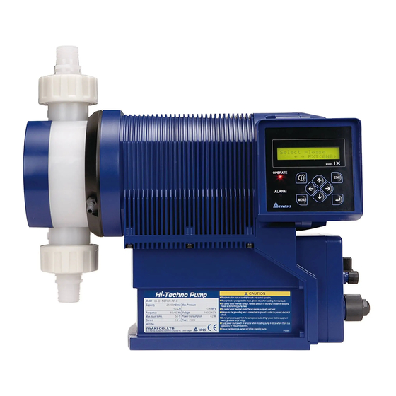
Part names Pump Control unit Used for the start/stop of the pump and operation control/ programming. See next page for detail. Outlet Bolt cover Take out the cover to remove the pump head. Nameplate Describes the pump specifi- cations. Inlet Base Always anchor it with bolts. -
Page 21: Operational Panel
Operation panel Display An operational status, a selected mode and programmed values are shown here. Start/Stop key Used for starting/stopping the pump operation or moving back to the MAN/ EXT selection. ESC key Used for cancelling pro- gramming and moving back to a previous menu. -
Page 22: Basic Displays & Pump States
■ Basic displays and Pump states Operation LED Operation LED Operation LED ALARM LED Display lights in red lights in green lights in orange lights in red Operation in ― ― ― manual mode Operation in EXT ― mode (Analogue ―... -
Page 23: Identification Codes
Identification codes Each code represents the following information. Pump IX - C 150 TC R - TB - E a. Series name b. Drive unit c. Pump unit (Max flow) 150 : 150 [L/H] 060 : 60 [L/H] d. Wet end materials Code Pump head Ball valve... -
Page 24: Installation
Installation This section describes the installation of the pump, piping and wiring. Read through this section before work. Points to be observed Observe the following points when installing the pump. • Be sure to turn off power to stop the pump and related devices before work. •... -
Page 25: Pipework
Pipework ■ Piping layout Flooded suction application Suction lift application Accumulator/Chamber Pressure valve Accumulator/Chamber Pressure valve Relief valve Relief valve Air vent/ drain valve Air vent/drain valve Pump Calibration cylinder Calibration cylinder Pump Tank Tank NOTE • A suction line bore should be wider than the inlet bore of the pump. •... -
Page 26: Drain Port (Vent Hole)
Drain port (Vent hole) Leaked liquid drains through a drain port at the time of accidental diaphragm rupture. Use a chemically-resistant tube to the drain port to collect the liquid in a tank. NOTE • Do not plug the drain port. The port functions as a vent hole to keep the pressure in the pump head constant. •... -
Page 27: Wiring
Wiring Wiring for power voltage, earthing and external signals. Points to be observed Observe the following points during wiring work. • Electrical work should be performed by a qualified operator. Always observe applicable codes or regulations. • Observe the rated voltage range, or the electrical circuit in the control unit may fail. •... -
Page 28: Power Voltage/Earthing
Power voltage/Earthing Points to be checked • Check that power voltage is turned off. Insert the plug all the way seated in a socket. NOTE • Do not share a power source with a high power device which may generate surge voltage. Otherwise an elec- tronic circuit may fail. -
Page 29: Signal Wire Connection
Precautions for ON-OFF control by a mechanical relay The control unit is equipped with CPU. Always start/stop the pump by the STOP signal for ON-OFF control. Try not to turn on and off the main power. Otherwise, observe the fol- lowing points. -
Page 30: Input Signal
■ Input signal To make pulse-, batch-, interval batch- and analogue-control operation or to activate interlock function, connect signal wires to the EXT terminals via the DIN 5-pin connection. When using an open collector... Pay attention to polarity. Pulse (1) and Interlock (2) are plus (+), and COM (4) is minus (-). When using a no-voltage contact... -
Page 31: Aux Signal
■ AUX signal To activate AUX function, connect signal wires to the AUX terminal via the DIN 5-pin connection. When using an open collector... Pay attention to polarity. AUX (3) is plus (+), and COM (4) is minus (-). When using a no-voltage contact... Use a mechanical relay designed for an electronic circuit. -
Page 32: Operation
Operation This section describes pump operation and programming. Run the pump after pipework and wiring is completed. Before operation First check piping and wiring are correct. And then make commissioning before starting op- eration. Points to be checked Before operation, check if... •... -
Page 33: Commissioning
Commissioning Always make commissioning when first mounting the pump in your system or resuming operation after a long period of stoppage. Open an air vent and a suction line. Do not open a calibration line if any. Air vent valve Open Close Open... -
Page 34: Perform A Calibration
Perform a calibration Periodically make calibration to monitor an accurate flow through control display. The pump is calibrated by pumping clean water at the maximum operating pressure before shipping (in the absence of a designation by a user), however, make calibration again in an actual operating condition as necessary. -
Page 35: Calibration Process
Calibration process Obtain accurate flow volume per shot (e.g. about 16ml/shot for the 150C type, about 6ml/shot for the C060 type) by dividing the delivered liquid volume by the number of strokes. Fill a calibration cylinder with liquid. Open a calibration line to lead liquid from a supply tank to a calibration cylinder. And then close the suc- tion line and measure liquid volume in the cylinder. - Page 36 Start calibration operation. Push the Enter key after setting the number of strokes. The pump starts a countdown. The pump starts to run for the set number of Pump strokes as it comes to zero. starts Pump stops Measure liquid volume in the calibration cylinder again. Enter how much liquid has reduced.
-
Page 37: Operation Programming
Operation programming The pump operation is programmed and controlled by a control unit in different ways at each operation mode. Mode Parameters Setting ranges Default Mode selection MAN/EXT Analogue control 0-20mA/ 4-20mA/ 20-0mA/ 20-4mA 4-20mA 0.01560mL/PLS-300mL/PLS (C150) 0.01560mL/PLS Pulse control 0.00625mL/PLS-120mL/PLS (C060) 0.00625mL/PLS 15.6mL/PLS-300L/PLS (C150) -
Page 38: Programming Flow
Programming flow Power ON MAN/EXT selection Wait state Menu screen EXT mode MAN mode Operation EXT mode MAN mode keys to scroll. *See page 39 for setting at each menue. Operation programming... -
Page 39: Menu Screen
Menu screen Push the MENU key in the MAN/EXT selection mode and call up the menu screen. Use the right and left keys to scroll through each menu item and then push the Enter key to make a selection. Pushing the MENU key again or ESC key in the menu screen, the previous mode will be recalled. -
Page 40: Ext Mode Selection
■ EXT mode selection Mode selection screen Analogue control Pulse control Enter key to confirm key to return to menu screen key to scroll Batch control key to change values Interval batch control Profibus control Mode setting screen Analogue control <To next page>... - Page 41 Pulse control Set flow volume per pulse. Batch control Set flow volume per pulse. Interval batch control Set “Day”. Set “Hour”. Set “Minute”. Set a flow rate. Profibus control Set an address. Operation programming...
-
Page 42: Calibration
■ Calibration *See page 34 "Calibration process" for detail. Enter key to confirm key to return to menu screen key to select key to change values ■ Signal input setting Function selection screen STOP function Pre-STOP function Enter key to confirm key to return to menu screen Interlock function key to scroll... - Page 43 Pre-STOP function Closed=Pump OFF : Operation LED lights in orange at contact input. Closed=Pump ON : Operation LED does not lights at contact input. Interlock function Closed=Pump OFF : Pump stops running at contact input. Closed=Pump ON : Pump starts to run at contact input.
-
Page 44: Alarm 1 Setting
■ Alarm 1 setting : OUT1<Mechanical relay> Output selection screen STOP function Pre-STOP function Enter key to confirm Overload detection key to return to menu screen Interlock function key to scroll key to change values Diaphragm rupture detection Output setting screen STOP function Disable : OUT1 does not work as the STOP function. -
Page 45: Alarm 2 Setting
Diaphragm rupture detection Disable : OUT1 does not work at diaphragm rupture. Enable : OUT1 works at diaphragm rupture. Overload detection Disable : OUT1 does not work at overload detection. Enable : OUT1 works at overload detection. ■ Alarm 2 setting : OUT2<PhotoMOS relay> Alarm 2 is programmed in the same way as the Alarm1. -
Page 46: Data Logging
■ Data logging Data logging screen Operating time Total flow volume Enter key to confirm Software version key to return to menu Powered-on time key to scroll Press 3 sec to delete data Number of ON/OFF 3 sec Return to a previous screen. *A selected data will be cleared except the version information. -
Page 47: Programming Of Other Functions
■ Programming of other functions Other selection screen Suction speed AUX speed Enter key to confirm key to return to menu screen Diaphragm position Language selection key to scroll key to change values Anti chattering Flow rate unit Other setting screen Suction speed <To next page>... - Page 48 AUX speed Set a flow rate. Diaphragm position MAX OUT Pos. : The diaphragm comes to the top dead point. MAX IN Pos. : The diaphragm comes to the bottom dead point. Either one of the above indication keeps flashing as long as the diaphragm is at either end.
- Page 49 Language selection Operation programming...
-
Page 50: Operation
Operation Read this section before operation. Manual operation Run or stop the pump by keypad operation. Supply the rated power voltage to the pump. The operation LED lights in red colour, and a previous mode at the last shutoff returns. * The pump enters the MAN/EXT selection mode when turning on power with a default setting. -
Page 51: Aux Function
Push the right key to select EXT and the Enter key to enter that choice. Waiting state display *The pump enters Analogue, Pulse, Batch or Interval Batch mode. Push the start/stop key to start operation. The pump runs along with operation program- ming and the external signal. -
Page 52: Keypad Lock
Keypad lock Keypad lock can be active for the prevention of erroneous key operation. NOTE • Any key operation is not acceptable when the keypad lock is active. In an emergency, pressing the start/stop key for two seconds, the pump enters a wait state and stops running. Release this state to resume operation. •... -
Page 53: Maintenance
Maintenance This section describes troubleshooting, maintenance, wear part replace- ment, exploded views and specifications. Points to be observed Observe the following points during maintenance work. • Follow instructions in this manual for replacement of wear parts. Do not disassemble the pump beyond the extent of the instructions. -
Page 54: Troubleshooting
Troubleshooting First check the following points. If the following measures do not help remove problems, con- tact your nearest distributor. ■ Pump States Possible causes Solutions The pump does not run Power voltage is too low. • Observe the allowable voltage range of ( The operation LED 90-264VAC. -
Page 55: Error Messages
Error messages Take measures below when error messages appear during operation. Contact us or your nearest distributor as necessary. Error messages Possible causes Measures • Check a discharge line for clogging and remove Pressure overload protection is it as necessary. If this error happens during the active. -
Page 56: Wear Part Replacement
Wear part replacement To run the pump for a long period, wear parts need to be replaced periodically. It is recommended that the following parts are always stocked for immediate replacement. Contact your nearest distributor for detail. Precautions • Solution in the discharge line may be under pressure. Release the pressure from the dis- charge line before disconnecting plumbing or disassembly of the pump to avoid solution spray. - Page 57 Pump head Parts # of parts Estimated life C150 Retainer 8000 hours (IX0015) (IX0051) (IX0048) Valve set (IX0047) (TC type) 2 sets 8000 hours (IX0049) IX0069 (IX0051) (IX0053) (IX0051) (IX0052) (IX0048) Valve set (IX0047) (TE type) 2 sets 8000 hours (IX0050) IX0070 (IX0052)
-
Page 58: Before Replacement
Before replacement Stop pump operation. Close the suction line. Close Open the drain valve to release liquid out of the discharge line. NOTE Open the valve gradually. Chemicals may be purged if the Drain valve discharge line pressure maintains higher pressure than atmos- pheric pressure. -
Page 59: Diaphragm Replacement
Take out valve sets from the pump head. Clean the pump head as necessary. Valve set Take apart valve sets and replace wear parts with new ones as necessary. Reassemble and remount the valve sets in the pump head. Observe the mounting order and direction of valve set components. See the exploded view at each model. - Page 60 Remove the bolt cover by a 3mm hexagon wrench (TC/TE types). Hexagon wrench Bolt cover Use a 13mm or a 8mm spanner to remove the pump head fixing bolts (eight M8 bolts for the C150/ six M5 bolts for C060) and detach the pump head with a reinforcing plate. Pump head Reinforcing plate (TC/TE types) Extend the pump shaft by keypad operation.
- Page 61 Clean the retainer or replace it with a new one. Apply grease (Dow Corning Toray MO- LYKOTE HP-500) on its surface and screw burning protective agent to the shaft of a ® new diaphragm. Fit a new diaphragm and the retainer into the pump shaft. Slide the retainer, dome end first, onto the diaphragm shaft.
- Page 62 Fix the bolt cover by the hexagon wrench (TC/TE types). Connect pipes to the fittings and then tighten the nuts. NOTE Check if the valve set mounting direction is correct. Both the valve sets must be oriented to the same direction. Valve set Go back to the waiting state.
-
Page 63: Exploded View
Exploded view Pump head, Drive unit & Control unit Do not dismantle the pump beyond the extent shown in the diagram below. Drive unit Pump head *Pump head material and size differ with models. Exploded view... -
Page 64: Pump Head
Pump head ■ IX-C150 TC R Part names # of parts Pump head Valve Valve guide Valve seat Out seat holder In seat holder O ring O ring Hex socket head bolt Hexagon head bolt Spring washer Bolt cover Reinforcing plate Diaphragm Retainer plate Fitting... -
Page 65: Ix-C150 Tc Fj
■ IX-C150 TC FJ Part names # of parts Pump head Valve Valve guide Valve seat Out seat holder In seat holder O ring O ring Hex socket head bolt Hexagon head bolt Spring washer Bolt cover Reinforcing plate Diaphragm Retainer plate Flange unit Exploded view... -
Page 66: Ix-C150 S6 R
■ IX-C150 S6 R Part names # of parts Pump head Valve Valve guide Valve seat Valve gasket Hexagon head bolt Spring washer Diaphragm Retainer plate Setting flange Fitting Hexagon head bolt Exploded view... -
Page 67: Ix-C150 S6 Fj
■ IX-C150 S6 FJ Part names # of parts Pump head Valve Valve guide Valve seat Valve gasket Hexagon head bolt Spring washer Diaphragm Retainer plate Flange unit Hexagon head bolt Exploded view... -
Page 68: Ix-C060 Tc R
■ IX-C060 TC R Part names # of parts Pump head Valve Valve guide Valve seat O ring Seat holder Adapter Hex socket head bolt Hexagon head bolt Spring washer Plain washer Bolt cover Reinforcing plate Diaphragm Retainer plate Fitting Exploded view... -
Page 69: Ix-C060 Tc Fj
■ IX-C060 TC FJ Part names # of parts Pump head Valve Valve guide Valve seat O ring Seat holder Adapter Hex socket head bolt Hexagon head bolt Spring washer Plain washer Bolt cover Reinforcing plate Diaphragm Retainer plate Flange unit Exploded view... -
Page 70: Ix-C060 S6 R
■ IX-C060 S6 R Part names # of parts Pump head Valve Valve guide Valve seat Valve gasket Valve cap Hexagon head bolt Spring washer Plain washer Diaphragm Retainer plate Fitting Exploded view... -
Page 71: Ix-C060 S6 Fj
■ IX-C060 S6 FJ Part names # of parts Pump head Valve Valve guide Valve seat Valve gasket Valve cap Hexagon head bolt Spring washer Plain washer Diaphragm Retainer plate Flange unit Exploded view... -
Page 72: Specifications/Outer Dimensions
Specifications/Outer dimensions Specifications Information in this section is subject to change without notice. ■ Pump Discharge Power con- Current Flow rate Weight Model code pressure sumption value Connection R3/4 IX-C150 TC/TE JIS10K20A 0.2-150 R3/4 IX-C150 S6 JIS10K20A R1/2 IX-C060 TC/TE JIS10K15A 0.08-60 R1/2... -
Page 73: Control Unit
■ Control unit MAN (Manual) A flow rate is set with (Up) and (Down) keys. Analogue control 4-20/ 0-20/ 20-4/ 20-0mA 0.01560mL/PLS - 300mL/PLS (C150) Pulse control 0.00625mL/PLS - 120mL/PLS (C060) 15.6mL/PLS - 300L/PLS (C150) Operation Batch control 6.25mL/PLS - 120L/PLS (C060) modes 0-9day, 0-23hr, 1-59min Interval batch... -
Page 74: Outer Dimensions
Outer dimensions ■ IX-C060/-C150 TC/TE R/N-TB Centre of inlet/lutlet IX-C150 TC/TE R/N IX-C060 TC/TE R/N 339.5 102.5 Specifications/Outer dimensions... -
Page 75: Ix-C060/-C150 Tc/Te Fj/Fd/Fa-Tb
■ IX-C060/-C150 TC/TE FJ/FD/FA-TB Centre of inlet/lutlet IX-C150 TC/TE FJ/FD/FA ─ ─ IX-C060 TC/TE FJ/FD/FA ─ 339.5 ─ 102.5 Specifications/Outer dimensions... -
Page 76: Ix-C060/-C150 Tc/Te R/N-Rf
■ IX-C060/-C150 TC/TE R/N-RF (115) Centre of inlet/lutlet IX-C150 TC/TE R/N IX-C060 TC/TE R/N 339.5 102.5 Specifications/Outer dimensions... -
Page 77: Ix-C060/-C150 Tc/Te Fj/Fd/Fa-Rf
■ IX-C060/-C150 TC/TE FJ/FD/FA-RF (115) Centre of inlet/lutlet IX-C150 TC/TE FJ/FD/FA ─ ─ IX-C060 TC/TE FJ/FD/FA ─ 339.5 ─ 102.5 Specifications/Outer dimensions... -
Page 78: Ix-C060/-C150 S6 R/N-Tb
■ IX-C060/-C150 S6 R/N-TB Centre of inlet/lutlet IX-C150 S6 R/N 333.5 96.5 IX-C060 S6 R/N Specifications/Outer dimensions... -
Page 79: Ix-C060/-C150 S6 Fj/Fd/Fa-Tb
■ IX-C060/-C150 S6 FJ/FD/FA-TB Centre of inlet/lutlet IX-C150 S6 FJ/FD/FA ─ 333.5 ─ 96.5 IX-C060 S6 FJ/FD/FA ─ ─ Specifications/Outer dimensions... -
Page 80: Ix-C060/-C150 S6 R/N-Rf
■ IX-C060/-C150 S6 R/N-RF (115) Centre of inlet/lutlet IX-C150 S6 R/N 333.5 96.5 IX-C060 S6 R/N Specifications/Outer dimensions... -
Page 81: Ix-C060/-C150 S6 Fj/Fd/Fa-Rf
■ IX-C060/-C150 S6 FJ/FD/FA-RF (115) Centre of inlet/lutlet IX-C150 S6 FJ/FD/FA ─ 333.5 ─ 96.5 IX-C060 S6 FJ/FD/FA ─ ─ Specifications/Outer dimensions... - Page 84 IWAKI Norge AS TEL : (47)23 38 49 00 FAX : 23 38 49 01 China IWAKI Pumps (Guangdong) Co., Ltd. TEL : (86)750 3866228 FAX : 750 3866278 Singapore IWAKI Singapore Pte. Ltd. TEL : (65)6316 2028 FAX : 6316 3221 China GFTZ IWAKI Engineering &...
Need help?
Do you have a question about the IX-C150 TC/TE R and is the answer not in the manual?
Questions and answers