
Related Manuals for IWAKI EW Series


Summary of Contents for IWAKI EW Series
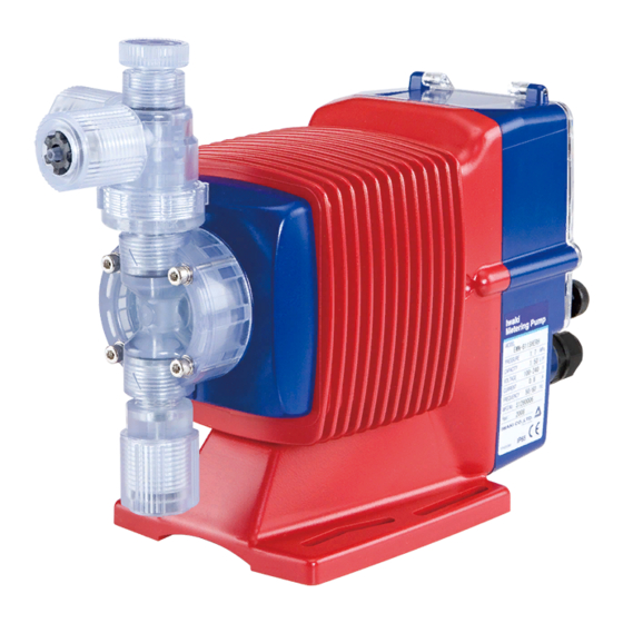
- Page 1 IWAKI Electromagnetic Metering Pump EW Series Instruction Manual Read this instruction manual before use of product...
-
Page 2: Table Of Contents
Thank you for selecting the electromagnetic metering pump EW series. This instruction manual deals with “Safety Section” “Product outline” “Installation Section” “Operation Section” and “Maintenance Section”. Please read through this manual carefully to ensure the optimum performance, safety and service of the EK series. -
Page 3: Important Instruction
Important Instructions For the Safe and Correct Handling of the Pump ● "Safety Instruction" section mentions important details about the handling of the product. Before the use of pump, read this section carefully for the prevention of personnel injury or loss. ●... -
Page 4: Safety Instructions
Prohibited • No remodeling Never remodel a pump. Otherwise, a serious accident may result. Iwaki will not be responsible for any accident or damage of any kind which is caused by the user No Remodeling remodeling the pump without first obtaining permission or instructions from Iwaki. - Page 5 Safety Instructions CAUTION • Do not run the pump dry Do not run the pump dry (without liquid inside the pump). Heat generated as a result of abrasion between elements inside the pump during operation without liquid may Prohibited damage the inside of the pump. •...
- Page 6 Safety Instructions CAUTION • Follow the instruction manual Replace the consumable parts by following the descriptions in the instruction manu- al. Do not disassemble any part of the pump if the disassembling procedure for the part in question is not included in the instruction manual. •...
-
Page 7: Outline
Outline 1.Unpacking & Inspection ....... 6 2.Operation Principle ......6 3.Identification Codes ......7 4.Specifications ........8 5.External Dimensions ......11 6.Main Parts & Label ......15 - 5 -... -
Page 8: Unpacking & Inspection
[2] Has the pump been damaged in transit? Are the bolts and nuts loose? 2. Operation Principle The Iwaki EW series electromagnetic pump is a diaphragm metering pump of the 'linear electromagnetic drive system', which means electromagnetic force drives the diaphragm directly. -
Page 9: Identification Codes
Outline 3. Identification Codes ■ Pump Identification EW - F 11 VC - 20E P F 2 - Series code Drive unit type Code Power consumption Stroke length 16 W 1.25 mm 24 W 1.5 mm Diaphragm diameter Code Effective diameter [mm] Wet end material Code Pump head... -
Page 10: Specifications
Outline Power cord Code Cord end No code Crimp-style terminals With plug Controller code F : F type controller Connection hose Code Hose diameter ø 4 × ø 6 ø 6 × ø 8 ø 9 × ø 12 ø 10 × ø 12 Rc1/4”... - Page 11 Outline <SH, TC> Max. Max. discharge Discharge Stroke Stroke discharge Model capacity capacity/shot rate length pressure L/H (ml/min) EW-F11 1.5 ( 26) 0.142 1 - 180 1.25 EW-F16 2.4 ( 40) 0.233 1 - 180 EW-G21 4.7 ( 78) 0.433 1 - 180 EW-G31 9.9 (165)
- Page 12 Outline ■ Controller specifications MANUAL (Manual operating) Function EXT: 1 point (Operation by external signal) Function STOP: 2 points (Stop by external signal) Change Three keys of UP, DOWN and START/STOP MANUAL Stroke rate: 1 - 180 spm Setting Control Digital input operation : 1 : 1 (No pulse memory, Max.
-
Page 13: External Dimensions
Outline 5. External Dimensions ● EW-F11, F16, F21, G21 Types (VC, VH, PC, PH, TC) (254.5) (37) (67.5) (22.5) ● EW-F31, G31 Types (VC, VH, PC, PH, TC) (235.5) (67.5) (24.5) - 11 -... - Page 14 Outline ● EW-G36 Type (VC, VH, PC, PH, TC) (235) (67.5) (24) 15 20 20 15 ● EW-G46 Type (VC, VH, PC, PH, TC) (237) (67.5) (26) - 12 -...
- Page 15 Outline ● EW-F11, F16, G21 Types (SH) (231.5) (15) Rc1/4 (9) (67.5) (21.5) ● EW-G31 Type (SH) (233) Rc1/4 (9) (67.5) (23) - 13 -...
- Page 16 Outline ● EW-G36 Type (SH) (233) Rc1/4 (9) (67.5) (23) 15 20 20 15 ● EW-G46 Type (SH) (235) Rc1/4 (9) (67.5) (25) - 14 -...
-
Page 17: Main Parts & Label
Outline 6. Main Parts & Label Air vent adjusting screw Drive unit Air vent port Control unit Make sure to connect a tube to return removed air back to the suction-side tank. Discharge port Pump unit Nameplate label Operate the pump in accordance with the specifications mentioned in the label. -
Page 18: Installation
Installation 1.Before Use ......... 17 2.Notes on Operation ......17 3.Installation, Piping, & Wiring ....20 - 16 -... -
Page 19: Before Use
Installation 1. Before Use “Strictly observe the following points.” Operators and maintenance service staff must read the instruction manual thoroughly before using the products. Do not operate the pump system unless all of the contents in the manual are completely understood. CAUTION ●... - Page 20 Installation ● The pump can be operated outdoors, as the pump employs a simple water and dust proof structure. However, when installing the pump, avoid places exposed to direct sunlight or direct rain with an ambient temperature of above 40ºC, or with a rela- tive humidity of above 90%.
- Page 21 Installation ● Limited operating site and storage Do not install or store the pump in the following places: * Places where a flammable gas or material is used or stored. Prohibited * Place where the ambient temperature is extremely high (40ºC or higher) or extremely low (0ºC or lower).
-
Page 22: Installation, Piping, & Wiring
Installation 3. Installation, Piping, & Wiring CAUTION ● When you detect or become aware of a dangerous sign or abnormal condition during operation, stop the operation and restart the procedure from the beginning. ■ Installation [1] Installation Install the pump at a site where the ambient tem- perature does not exceed 40ºC and the relative humidity does not exceed 85%. - Page 23 Installation ■ Piping <For material codes VC, VH, PC, PH, TC> Tube [1] Piping for pump connection port Use the tube with the correct diameter and make Fitting nut sure the connecting section does not cause liquid leakage or air suction. Connecting port CAUTION Since the fitting nut is made of plastic resin,...
- Page 24 Installation [3] Installation of check valve (Optional accessory) The check valve is used to prevent overfeeding. The check valve must be installed in any of the fol- lowing cases. CA Type Check Valve (1) In case the suction-side liquid level is higher than that of the discharge-side level.
- Page 25 ● Procedure to connect the external signal cord Use DIN connector of five poles and four poles. Following connectors made by Binder in Germany are recommended. Ask IWAKI for the detail of Binder connector. 5 poles: 713 Series 99-0436-10-05 4 poles: 715 Series 99-0430-15-04 Following procedures are based on the connector made by Binder in Germany.
- Page 26 Installation ● Connection of level sensor The controller corresponds to two stage level sensor. Connect pre-alarm signal to Pre-STOP and alarm signal to STOP. When the pre-alarm signal comes in, orange lamp is lighted but the pump does not stop. When one contact type is used, connect the wires to STOP and COM2.
- Page 27 Installation ● Output signal OUT1 : STOP output Output signal is activated when the pump stops by the external signal such as level sensor or so. OUT2 : Output synchronous with stroke Signal is activated synchronous with each pump stroke (shot). Connection inside connector: 1 : OUT COM 2 : Free...
-
Page 28: Operation
Operation 1.Bleeding ..........27 2.Flow rate Adjustment ......29 3.Operation ........... 31 - 26 -... -
Page 29: Bleeding
Operation 1. Bleeding After the installation, piping, and wiring processes are completed, operate the pump in accordance with the following steps. CAUTION ● Do not operate the pump with a completely closed discharge-side valve. Operating the pump with the discharge-side valve fully closed may lead to liquid leakage or pipe rupture. - Page 30 Operation SH type [4] Rotate the air vent adjusting screw clock- Air vent wise to close the air vent valve adjusting screw Male connector [5] Inspect various points for liquid leakage to complete the air elimination process. <Bleeding for EW-F31, G31, 36, 46 models> [1] Extend the tube connected with the dis- charge-side fitting nut of the pump to the liquid tank or something like a drain plate.
-
Page 31: Flow Rate Adjustment
Operation 2. Flow rate Adjustment The discharge amount can be adjusted by two methods, namely, stroke speed adjustment and stroke length adjustment, the former being used in most cases. In the event the expected discharge is not exactly obtained by the stroke speed adjustment, the stroke length adjustment is employed as a supplementary. [1] Procedure for flow rate adjustment 180 spm Fixed stroke rate... - Page 32 Operation [3] Adjustment of stroke length Stroke length can be adjusted by changing the degree of plunger return. (1) Start the pump and rotate the stroke length adjusting dial while operating the pump to adjust the discharge amount. (2) The relation between discharge amount and stroke length is as shown in the Fixed stroke rate graph on the left, where the discharge...
-
Page 33: Operation
Operation 3. Operation ■ Control panel Display Set value and operating condition are displayed. Start/Stop key UP key Key to start and stop Key to increase the stroke rate the pump in the manual and to change the set value. operation mode. - Page 34 Operation ■ Main menu Wait display UP stroke rate DOWN stroke rate Power ON EXT mode WAIT mode Set mode Manual operation mode Setting display Select Operating at max. Move spm while both keys MANUAL operation display are pressed. next EXT operation display UP stroke rate DOWN stroke rate...
- Page 35 Operation ■ Operation Power ON When the power is ON, the display shows WAIT mode after the program version code is momentarily displayed. (When the power is switched on initially.) Once the initial power is switched on, it returns to the mode at which the power was off last time.
- Page 36 Operation Setting of function Moving to WAIT mode If it is in MANUAL operation or in SET mode, set to WAIT mode. If it is in WAIT mode, go to next step. Moving to SET mode Press START/STOP and ▲ keys at the same time and it displays anti-chattering function.
-
Page 37: Maintenance
Maintenance 1.Causes of Trouble & Troubleshooting ......36 2.Maintenance & Inspection ....37 3.Disassembly & Reassembly ....38 4.Accessories ........42 5.Names of Parts & Structure ....43 - 35 -... -
Page 38: Causes Of Trouble & Troubleshooting
Do not try to carry out a service or maintenance work beyond or against the descriptions included in this manual. Iwaki takes no responsibility for injuries or damages to assets caused by the user’s failure to observe the instructions mentioned in this manual. -
Page 39: Maintenance & Inspection
Maintenance 2. Maintenance & Inspection ■ Daily check Pay attention to the following points during pump operation, and stop pump operation immediately in the event of an abnormality. Take the necessary measures, with reference to the “Causes of Trouble and Troubleshooting”... -
Page 40: Disassembly & Reassembly
Maintenance 3. Disassembly & Reassembly Follow the disassembly and reassembly procedures described below when disassembling or reassembling the pump as necessary for such purposes as replacing expendable parts or overhauling the pump for clean- ing. <Points to be confirmed before disassembly> •... - Page 41 Maintenance [2] Removal of the valve set on the suction side. (1) Loosen the fitting nut(4) and detach the tube from the pump. • Pay attention to the residual liquid which may flow out of the end of the disconnected tube. Use a wrench to loosen and remove the connecting port.
- Page 42 Maintenance ■ Replacement of valve set of material Air vent adjusting screw code SH (Refer to exploded view on Air vent body A page 45.) <Disassembly of discharge valve> Lock nut 1) Remove every hose and pipe. 2) Turn the lock nut to left with wrench to remove air vent body.
- Page 43 Maintenance ■ Air vent assembly Use a wrench to loosen the lock nut(6). Since the air vent unit(A) can be rotated 90 degrees, Air vent unit A (5) the tube connection position can be selected freely to satisfy your requirements. The lock Lock nut (6) nut shall be loosened to make sure that the tube is not positioned over the pump head.
-
Page 44: Accessories
Maintenance [3] Attach the pump head onto the pump body. Tighten the four hex. socket bolts by apply- ing an equal amount of torque to them. • Tightening torque: EW-11, 16, 21 : 2.16N·m EW-31 : 2.55N·m EW-36 · 46 : 2.95N·m 4. -
Page 45: Names Of Parts & Structure
Maintenance 5. Names of Parts & Structure ■ Exploded view All the parts are shown as disassembled for a clear understanding of their names and the structure of the pump. For the procedures involved in disassembling the pump, make sure to observe the disassembly instructions included in the “Maintenance”... - Page 46 Maintenance ■ Pump Unit ● EW-F11, F16, F21, G21 Types (VC, VH, PC, PH, TC) Name Quantity Pump head Fitting 1 (2) Fitting nut 3 (2) Air vent body B 1(0) Lock nut 1(0) Diaphragm Retainer Air vent body A 1(0) Valve guide Valve seat...
- Page 47 Maintenance ● EW-F11, F16, G21, G31, G36, G46 Types (SH) Parts name Q’ty Pump head Fitting Diaphragm Retainer Valve guide Valve seat Valve Valve gasket B Diaphragm spacer (NOTE) Hex. socket cap bolt (with SW, PW) Plate washer Spring washer Valve gasket A Adjusting screw Seal nut...
- Page 48 IWAKI CO.,LTD. 6-6 Kanda-Sudacho 2-chome Chiyoda-ku Tokyo 101-8558 Japan TEL:(81)3 3254 2935 FAX:3 3252 8892(http://www.iwakipumps.jp) U.S.A. : IWAKI America Inc. TEL : (1)508 429 1440 FAX : 508 429 1386 Germany : IWAKI EUROPE GmbH TEL : (49)2154 9254 0 FAX : 2154 1028 Australia : IWAKI Pumps Australia Pty.
Need help?
Do you have a question about the EW Series and is the answer not in the manual?
Questions and answers