
Related Manuals for IWAKI FW-H Series


Summary of Contents for IWAKI FW-H Series
- Page 1 IWAKI Pneumatic Drive Bellows Pump FW-H Instruction Manual Read this manual before use of product...
-
Page 2: Table Of Contents
Thank you for selecting an Iwaki Pneumatic Drive Bellows Pump the FW-H. This instruc- tion manual deals with “Safety instructions”, “Outline”, “Installation”, “Operation” and “Maintenance” sections. Please read through this manual carefully to ensure the optimum per- formance, safety and service of your pump. -
Page 3: Important Instructions
Important instructions For the Safe and Correct Handling of the Pump ● "Safety Instruction" section deals with important details about handling of the product. Before use, read this section carefully for the prevention of personal injury or property damage. ● Observe the instructions accompanied with "WARNING" or "CAUTION" in this manual. These instructions are very important for protecting users from dangerous situations. -
Page 4: Safety Instructions
Safety instructions WARNING ● When turning on power Make sure there is no one around the pump when connecting the power cable. Any power supply switch is not provided on the pump. Connecting the power cable, a solenoid valve starts to supply air to run the pump. ●... - Page 5 Safety instructions CAUTION ● Power OFF Be sure to turn off the power before a maintenance/repair work. Make sure no one turns on the power while working on the pump, otherwise a serious accident may result. If your work field is noisy or dark, let other people know about the situation by displaying a notice such as "POWER OFF(Maintenance)"...
- Page 6 Safety instructions CAUTION ● Supply air pressure Observe the supply air pressure range below. Otherwise the bellows may deform. Pump model Liquid temperatrue range Supply air pressure range 10-100°C 0.196-0.490MPa FW-20HT1 101-150°C 0.147-0.294MPa FW-20HT2 151-180°C 0.147-0.196MPa 10-100°C 0.196-0.490MPa FW-40HT1 101-150°C 0.147-0.294MPa FW-40HT2 151-180°C...
-
Page 7: Outline
Outline 1. Unpacking & Inspection ......6 2. Operating principle........ 6 3. Model codes ......... 7 4. Specifications ........7 5. Outer dimensions ........8 6. Part names ........... 9 7. Overview ..........13 - 5 - - 5 -... -
Page 8: Unpacking & Inspection
(The AC-1, FD-2, SC and FDC-1) b. Quick exhaust valves Wiring work is different at each controller type. 2. Operating principle An Iwaki pneumatic drive bellows pump has fluoric wet ends and is designed for semicon- Bellows Air chamber ductor manufacturing processes. -
Page 9: Model Codes
Outline 3. Model codes FW - 20 H T 1 - 01 a. Series code b. Maximum flow rate 20 : 20 L/min 40 : 40 L/min c. Temperature range T : 10-180°C d. Pump connection (Inlet/Outlet) T : Tube (standard) e. -
Page 10: Outer Dimensions
Outline 5. Outer dimensions FW-20HT Unit: mm 2- ø19 × ø16 AIR SUP. 2-Rc1/4 (100) Weight: 14kg FW-40HT Unit: mm 2- ø25 × ø22 25.5 AIR SUP. 2-Rc3/8 (100) Weight: 24kg - 8 - - 8 -... -
Page 11: Part Names
Outline 6. Part names FW-20HT1 40 42 43 38 44 45 35 36 37 N: LEAK SENSOR 22 16 15 24 31 23 14 17 18 SECTION:N 21 13 30 29 Part names Materials Remarks Part names Materials Remarks Q'ty Q'ty Q'ty 1 Pump head... - Page 12 Outline FW-20HT2 40 42 43 38 44 45 35 36 37 N: LEAK SENSOR 22 16 15 24 31 14 23 17 18 SECTION:N 21 13 30 29 Part names Q'ty Materials Remarks Q'ty Part names Q'ty Materials Remarks 1 Pump head 1 PTFE 27 Screw 8 Stainless steel M4×8...
- Page 13 Outline FW-40HT1 35 36 37 N: LEAK SENSOR 11 47 Part names Q'ty Materials Remarks Q'ty Part names Q'ty Materials Remarks 1 Pump head 1 PTFE 28 Packing 2 FKM 2 Valve 4 PTFE 29 Bearing 2 Filled PTFE 3 Valve spring 4 PTFE 30 Stop ring 2 Stainless steel Nominal 37...
- Page 14 Outline FW-40HT2 35 36 37 N: LEAK SENSOR Part names Q'ty Materials Remarks Q'ty Part names Q'ty Materials Remarks 1 Pump head 1 PTFE 28 Packing 2 FKM 2 Valve 4 PTFE 29 Bearing 2 Filled PTFE 3 Valve spring 4 PTFE 30 Stop ring 2 Stainless steel Nominal 37...
-
Page 15: Overview
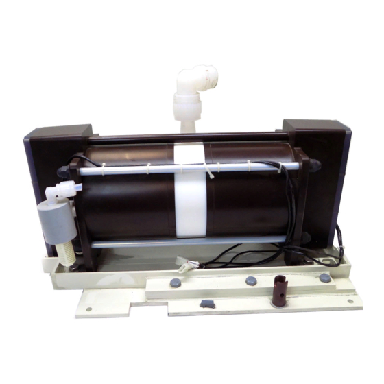
Outline 7. Overview CAUTION Do not wipe the labels or the pump body with solvent. Outlet Name plate OUT label Air port Air port Caution label (T1 type only) IN label Inlet Base Wires Fix the pump. Proximity switch and electrode wires. -
Page 16: Installation
Installation 1. Before installation ....... 15 2. Installation/Piping/Wiring ....17 - 14 -... -
Page 17: Before Installation
● Some strippers may cause cracks on the bellows or piping • Stripper (PFA) at an early stage. Contact us for a warranty period • Solvent applied for such liquids. ● An explosion-proof construction are required for solvents. Contact Iwaki for details. - 15 -... - Page 18 Installation Points to be checked Description CAUTION Always stop the pump while Stopping the pump without releasing discharge releasing discharge pressure. pressure may deform the bellows. CAUTION Do not leave the pump unused for a long period with a liquid in the Some chemicals may penetrate component parts pump.
-
Page 19: Installation/Piping/Wiring
Installation 2. Installation/Piping/Wiring Stop working upon perceiving any danger or abnormal sign. WARNING Be sure to turn off the power before starting any maintenance/repair work. Make sure no one turns on the power while working on the pump, otherwise it may result in a serious accident. - Page 20 Installation ■ Pipework Piping Pump head tube Tube fitting Piping Pump head tube Tube fitting 1. Inlet & outlet bores and materials PFA tubes are originally equipped to inlet & outlet of the pump. Tube bores are as follows. FW-20HT..3/4" (ø19×ø16) FW-40HT..1"...
- Page 21 Installation ■ Discharge line 1. The pipe resistance increases as a discharge line becomes longer or the number of bends increases. In order to decrease pipe resistance, install a dampener to minimizes pulsation. When sending a liquid up via a riser pipe, install a check valve. 2.
- Page 22 Installation ■ Degassing Gas bubbles are generated when a strong acid is fed into the reaction tank or liquid is transferred through a narrow tube. If such bubbles enter the bellows, the pump runs dry, increasing stroke rate or disturbing liquid transfer. Take a proper step for degassing. The stroke rate increment is a sign of dry running.
- Page 23 Installation ■ Air piping CAUTION • Supply air should be free from moisture and dust. If the supply air is contaminated with water, oil or dust, the pump may fail in starting. If water enters the air chambers, the electrodes may detect it and sounds an alarm. •...
- Page 24 Installation 3. Solenoid valve Select a five-port solenoid valve according to the table below. Pump model Effective cross-sectional area Supply air port bore FW-20HT 25mm or more Rc 1/4" or more FW-40HT 50mm or more Rc 3/8" or more CAUTION Select a 2-position type when using a double-solenoid valve.
- Page 25 Installation 6. Quick exhaust valve The air from the pump is exhausted via the exhaust ports of the solenoid valve (Fig. 1). Some chemical generates permeable gas. The gas may mix with the exhaust air and may corrode the solenoid valve. In this case install quick exhaust valves between the pump and the solenoid valve so that air will be exhausted through the quick exhaust valves (A slight amount of air will be exhausted through the solenoid valve.).
- Page 26 Installation ■ Precautions for air piping 1. Supply air port bore Supply air port bore on the pump FW-20HT : Rc 1/4" Supply air port (pump) (Tube bore shall be 8mm or more) Tube FW-40HT : Rc3/8" (Tube bore shall be 10mm or more) Tube coupling 2.
- Page 27 Installation ■ Effective cross-sectional area 1. Effective cross-sectional area In the field of pneumatic devices, the term “Effective cross-sectional area” is used to indicate actual air flow. When air is sent through a pipe, air cannot flow fully for the actual cross-sectional area due to piping resistance.
- Page 28 Installation ■ Wiring diagram The following shows a wiring diagram for the AC-1 (the FD-2, SC or FDC-1) controller and the five-port sole- noid valve. Refer to instruction manuals of each controller for further information. Wiring with the AC-1 controller Be sure to turn off the controller.
- Page 29 Installation 2. Wiring for electrode Connect white and black wires (approximately 1.8m), which are extended from both the right and left sides of the pump with controller terminals ► Join right and left white wires and connect it with controller terminal ►...
- Page 30 Installation ■ Wiring with the SC controller The diagram below shows the wiring diagram with the SC controller. See the instruction manual of the SC controller for detail. C-3G C-2G C-3G C-2G C-3G C-2G Power Source 24VDC SC controller C-5 (OUTPUT) C-4 (INPUT) Dampener Pump...
-
Page 31: Operation
Operation 1. Before operation ......... 30 2. Operation ..........30 3. Check items ........31 - 29 -... -
Page 32: Before Operation
Operation 1. Before operation Carry out the following preparatory steps when starting the pump for the first time after installation or after a long period of storage. 1. Check that the electric wiring is correct (Wiring for the proximity switches, electrodes and solenoid valve). CAUTION Improper wiring leads to proximity switch failure. -
Page 33: Check Items
Operation ■ Stopping the pump 1. Switch off the controller. The pump stops running and the LED goes out. 2. Make sure a discharge line is open when stopping the pump. CAUTION Do not close a discharge valve as stopping the pump. 3. - Page 34 Maintenance 1. Troubleshooting ........33 2. Maintenance & Inspection....35 3. Wear parts .......... 36 - 32 - - 32 -...
-
Page 35: Maintenance 1. Troubleshooting
Worn pump head valve ● Clean or replace the ○ Install a guard filter in a suction and valve seat pump* line. Check if a pump head valve is blocked with crystal. * means work by Iwaki. - 33 - - 33 -... - Page 36 ○ Install a filter or strainer in a suc- from the pump (Due to life end.) tion line. outlet ○ Install a filter or strainer in a dis- charge line. * means work by Iwaki. - 34 - - 34 -...
-
Page 37: Maintenance & Inspection
(Life span at each wear part differs with a liquid handled and oper- ating condition.) *Valve assembly and bellows replacement shall be conducted by Iwaki. 4. Pump operation after a long period of suspension Supply the air to the pump (approx. 0.294MPa) and confirm there is no air leakage from the outlet before operation. -
Page 38: Wear Parts
Maintenance 3. Wear parts The wear parts shown below should be replaced when it reaches the estimated life end or when performance deteriorates remarkably, whichever comes fast. Contact us. FW-20HT1 & -40HT1 Part names Q'ty Estimated life 1,2,3,4,48 Pump head unit 1 set 5,6,46 Bellows unit... - Page 39 IWAKI Norge AS TEL : (47)66 81 16 60 FAX : 66 81 16 61 China IWAKI Pumps (Guandong) Co., Ltd. TEL : (86)750 3866228 FAX : 750 3866278 Singapore IWAKI Singapore Pte. Ltd. TEL : (65)6316 2028 FAX : 6316 3221 China GFTZ IWAKI Engineering &...
Need help?
Do you have a question about the FW-H Series and is the answer not in the manual?
Questions and answers