
Related Manuals for IWAKI LK-A/-B TC


Summary of Contents for IWAKI LK-A/-B TC
- Page 1 IWAKI Metering pump LK-A/-B TC Instruction Manual Read this manual before use of product...
-
Page 2: Table Of Contents
Thank you for selecting an Iwaki LK-A/-B TC metering pump. This instruction manual deals with "Safety instructions", "Outline", "Installation", "Operation" and "Maintenance" sec- tions. Please read through this manual carefully to ensure the optimum performance, safety and service of your pump. -
Page 3: Important Instructions
Important instructions For the Safe and Correct Handling of the Pump "Safety Instruction" section deals with important details about handling of the product. Before use, read this section carefully for the prevention of personal injury or property damage. Observe the instructions accompanied with "WARNING" or "CAUTION" in this manual. These instructions are very important for protecting users from dangerous situations. -
Page 4: Safety Instructions
Safety instructions WARNING Turn off power before service Risk of electrical shock. Be sure to turn off power to stop the pump and relat- ed devices before service is performed. Turning off power Wear protective clothing Always wear protective clothing such as an eye protection, chemical resistant gloves, a mask and a face shield during disassembly, assembly or maintenance work. - Page 5 Safety instructions CAUTION Ventilation Fumes or vapours can be hazardous with certain solutions. Ensure proper ventilation at the operation site. Caution Do not bring the pump close to a flammable substance Keep the pump away from a flammable substance for the prevention of fire. Fire ban Do not touch the pump or pipe with bare hands Risk of burning.
- Page 6 Safety instructions CAUTION Do not cover the pump with cloth The motor temperature may build up and a fire or an electric/mechanical fail- ure may result. Prohibited Non-freezing Frozen liquid may damage the pump and piping. Drain liquid before leaving it for a long time or use measures to prevent liquid from freezing in winter.
- Page 7 Outline 1. Unpacking & Inspection ......6 2. Product outline ........6 3. Pump mechanism ......... 7 4. Specification ......... 8 5. Model code ........... 8 6. Overview ..........9 7. Part names (pump head) ....10 8. Precautions for use ......11 - 5 -...
-
Page 8: Outline
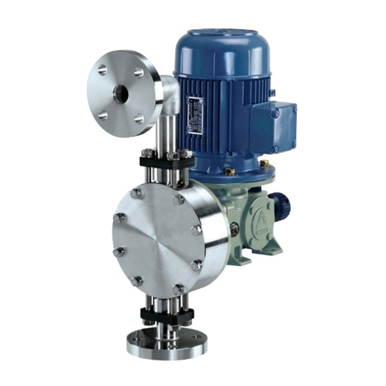
2. Check for transit damage, deformation, and loose bolts. Instruction manual 2. Product outline The LK-A/-B TC series is mechanically-driven dia- phragm pump. Fluoroplastic and alumina ceramic wet Outlet ends allow for delivery of various chemicals including Check valve Reduction strong acid in water treatment and chemical, paper &... -
Page 9: Pump Mechanism
■ Gear unit The gear unit of the LK-A/-B TC is spring back design consisting of a worm wheel shaft, a slider and a spring, etc. Motor rotation is transmitted to an worm wheel shaft and then converted to reciprocating motion of the pump shaft with the assistance of a slider and a spring. -
Page 10: Specification
Outline 4. Specification Approx Max flow Stroke rate Max discharge Max stroke Flange Motor weight /min Model pressure length size output (with JIS 10K 50Hz 60Hz 50Hz 60Hz motor)kgf LK-A55 1.0 (0.7) LK-A57 0.7 (0.5) LK-A65 0.3 (0.2) 10.8 17.5 LK-B65 0.75 * The above information is based on pumping clean water at ambient temperature. -
Page 11: Overview
Outline 6. Overview "Arrow" label Motor fan cover The arrow indicates a rotational direction of the motor. Make sure the motor runs in a correct direction. Motor nameplate Tightening torque indi- Apply the power voltage cation label specified on the name- Observe the indication plate. -
Page 12: Part Names (Pump Head)
Outline 7. Part names (pump head) LK-A55/-A57 TC Names Q'ty Pump head Flange unit (discharge side) Valve Valve guide Valve seat Valve gasket O ring Hex head bolt Spring washer Reinforcing plate Diaphragm Retainer Union Flange Flange adapter Flange unit (suction side) LK-A65/-B65 TC Names... -
Page 13: Precautions For Use
Outline 8. Precautions for use Always observe the following points. 1. Use care handling the pump. Do not drop. An impact may affect pump performance. Contact us or your nearest dis- tributor if a pump has been damaged. 2. Be careful not to exceed the maximum flow rate and discharge pressure. A flow rate and discharge pressure change with piping length, piping I.D., piping layout. -
Page 14: Installation 1. Before Installation
Installation 1. Before installation ....... 13 2. Installation ........... 14 3. Pipework ..........15 4. Wiring ..........17 - 12 -... -
Page 15: Installation
Installation 1. Before installation Always observe the following points. Observe information on the drawing and specification sheet. Allow sufficient space around the pump for easy access and maintenance. CAUTION Use care handling the pump. Do not drop. An impact may affect pump performance. Keep the pump Requirement level when lifting it up. -
Page 16: Installation
Installation 2. Installation Check if installation doesn't adversely affect facility, surrounding equipment and the pump. Install the pump according to the following instructions to ensure the optimum performance, safety and service. ■ Installation location • Allow sufficient space around the pump for easy access and maintenance. •... -
Page 17: Pipework
Installation 3. Pipework Foreign matters such as sand and scale may enter pipework while you are working. They may cause fatal damage to the pump. Be sure to blow them out before operation. Also, do not apply adhesive too much or leave a screw or nut. -
Page 18: Suction Line
Installation 10. If the pump is used to transfer a high or low-temperature liquid, install the flexible piping to protect the pump from the expansion and contraction of piping by thermal stress. 11. Do not apply adhesive too much, especially when using PVC discharge line. 12. -
Page 19: Wiring
Installation 4. Wiring Electrical work should be performed by a qualified electrician. Otherwise, personal injury or property damage could result. Wiring work should be done in accordance with the relevant regulations, using the recommended wir- ing accessories. 3-phase motor wiring diagram 1. - Page 20 Operation 1. Operational precautions ...... 19 2. Commissioning ........19 3. Operation ..........21 4. Flown rate adjustment ......22 5. Before/After a long period of stoppage ..23 - 18 -...
-
Page 21: Operation 1. Operational Precautions
Operation 1. Operational precautions WARNING Qualified personnel only This product should be handled or operated by qualified personnel with a full understanding. Any person not familiar with the product should not take part Requirement in the operation or maintenance of this product. Be sure to turn off all the related power supplies prior to any inspec- tion/maintenance and installation works (motor fan cover). - Page 22 Operation ■ Starting process Operate the pump by the following procedure. Operation procedure Remarks • Open the suction and dis- charge valves. • Turn on power to run the • Check the rotational direction of the motor. Clockwise seen from the pump.
-
Page 23: Operation
Operation ■ Points to be checked Check the following points during commissioning. If you notice any abnormal or dangerous conditions, suspend oper- ation immediately and inspect/solve problems. See Troubleshooting on page 25 or contact us. Operating conditions a. Check a liquid level in the supply tank and discharge capacity. b. -
Page 24: Flow Rate Adjustment
Operation 4. Flow rate adjustment Use the stroke length knob to determine the liquid volume per stroke. ■ Stroke length adjustment The adjustment should be made while the pump is running. Do not rotate the knob beyond the max or min position. A flow rate does not change beyond these positions. -
Page 25: Before/After A Long Period Of Stoppage
Operation 5. Before/After a long period of stoppage ■ Before a long period of stoppage 1. Solution in the discharge line may be under pressure. Release the pressure from the discharge line before discon- necting plumbing or disassembly of the pump to avoid solution spray. 2. - Page 26 Maintenance 1. Troubleshooting ........25 2. Maintenance & Inspection....28 3. Spare & Wear parts ......29 4. Dismantlement & Assembly ....30 - 24 -...
-
Page 27: Maintenance 1. Troubleshooting
Maintenance 1. Troubleshooting If you can not find out the root cause of failure, contact us. States Possible causes Solutions Motor failure Replace with new one. Disconnection Reconnect motor wires or replace the motor. Power fuse has blown. Inspect/solve the root cause of the blowout. Motor does not starts to run. - Page 28 Maintenance States Possible causes Solutions Motor failure Replace with new one. Disconnection Reconnect motor wires or replace the motor. Power voltage reduction Inspect/solve the root cause of the reduction. Foreign matters in the ball valve Take apart and clean the valve. Motor over current Clogged suction line or strainer Take apart and clean them.
- Page 29 Maintenance States Possible causes Solutions Clogged suction line or strainer Take apart and clean them. Over pressure (discharge line) Inspect/solve the root cause of the over pressure. Different liquid is used. Check liquid characteristics and pump specification. Damaged diaphragm Replace with new one. Liquid leaks.
-
Page 30: Maintenance & Inspection
Maintenance 2. Maintenance & Inspection WARNING Turn off power before service Risk of electrical shock. Be sure to turn off power to stop the pump and related devices before service is performed. Turning off power Wear protective clothing Always wear protective clothing such as an eye protection, chemical resistant gloves, a mask and a face shield during disassembly, assembly or mainte- Wear protective nance work. -
Page 31: Spare & Wear Parts
Maintenance ■ Oil replacement Replace the reduction gear oil every year or when deteriorated. 1. Loosen the drain plug and release old oil. 2. Pour flushing oil through the oil fill opening and Oil fill opening rinse the inside of the gear unit. 3. -
Page 32: Dismantlement & Assembly
Maintenance 4. Dismantlement & Assembly See the exploded view of the pump head before disassembly. See "7. Part names" on page 10 for detail. Clean the inside of the pump head in advance. Be careful not to drop the pump head. WARNING Risk of electrical shock. - Page 33 Maintenance ■ Valve set assembly process 1. Assemble the valve set. Note the valve guide, ball valve, valve seat and valve gasket have a mounting direction. Valve assembly NOTE: Observe the mounting direction of the O ring valve guide, ball valve, valve seat and Valve guide valve gasket.
- Page 34 Maintenance ■ Diaphragm replacement/assembly/disassembly WARNING Risk of electrical shock. Be sure to turn off power to stop the pump and related devic- es before service is performed. Solution in the discharge line may be under pressure. Release the pressure from the discharge line before disconnecting plumbing or disassembly of the pump to avoid solution spray.
- Page 35 Maintenance Assembly process Bracket 1. Check that the pump shaft is extended to the full. Top dead point Pump shaft 2. Fit the retainer into the pump shaft and screw the dia- phragm into the pump shaft. NOTE: The LK-6 has a rear seat. Take it in between the diaphragm and retainer.
- Page 36 Maintenance 5. Fit and tighten the motor fan cover with three screws. Flange gasket 6. Connect the suction and the discharge lines to the inlet and the outlet over the gaskets. Tighten the flange bolts to the same torque in diagonal order. NOTE: Use measures to keep the pump connec- tions fee from stress.
- Page 37 - 35 -...
- Page 38 - 36 -...
- Page 39 - 37 -...
- Page 40 IWAKI Norge AS TEL : (47)23 38 49 00 FAX : 23 38 49 01 China IWAKI Pumps (Guandong) Co., Ltd. TEL : (86)750 3866228 FAX : 750 3866278 Singapore IWAKI Singapore Pte. Ltd. TEL : (65)6316 2028 FAX : 6316 3221 China GFTZ IWAKI Engineering &...
Need help?
Do you have a question about the LK-A/-B TC and is the answer not in the manual?
Questions and answers