
Related Manuals for IWAKI EH-E 31


Summary of Contents for IWAKI EH-E 31
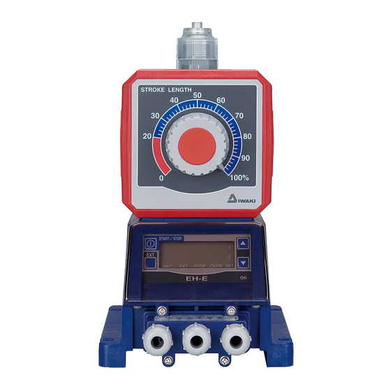
- Page 1 IWAKI Electromagnetic Metering Pump EH-E Type Instruction Manual Read this manual before use of product...
-
Page 2: Table Of Contents
Thank you for selecting the electromagnetic metering pump EH-E series. This instruction manual deals with “Safety Section” “Product outline” “Installation Section” “Operation Section” and “Maintenance Section”. Please read through this manual carefully to ensure the optimum performance, safety and service of the EH-E series. Contents . -
Page 3: Important Instruction
Important instructions For the Safe and Correct Handling of the Pump ● "Safety Instruction" section deals with important details about handling of the product. Before use, read this section carefully for the prevention of personal injury or property damage. ● Observe the instructions accompanied with "WARNING" or "CAUTION" in this manual. These instructions are very important for protecting users from dangerous situations. -
Page 4: Safety Instruction
Prohibited specifications and application range. ● No remodeling Never remodel a pump. Otherwise, a serious accident may result. Iwaki will not be responsible for any accident or damage of any kind which is caused by the user No Remodeling remodeling the pump without first obtaining permission or instructions from lwaki. - Page 5 Safety instructions CAUTION ● Qualified operators only The pump operator and pump operation supervisor must not allow any operators who have little or no knowledge of the pump to run and operate the pump. Pump operators must have a sound knowledge of the pump and its operation. Prohibited ●...
- Page 6 Safety instructions CAUTION ● Arrange grounding Do not operate the pump without connecting the grounding wire. Otherwise, an elec- trical shock may result. Make sure the grounding wire is connected with grounding Grounding terminal. ● Install an earth leakage breaker The operation of a pump without using an earth leakage breaker may cause an elec- trical shock.
-
Page 7: Outline
Outline 1. Unpacking ........... 6 2. Operating Principle ......6 3. Identification Code ......7 4. Features ..........9 5. Specification ........10 6. Operating Function ......11 7. Display and Keys ......13 - 5 -... -
Page 8: Unpacking
Outline 1. Unpacking After unpacking the goods, check the following Model Capacity Max. Pressure points to ascertain that the product is exactly as you ordered. If you find anything wrong, please get in touch with your dealer. (1) Do the model, voltage, etc., shown on the nameplate represent what you ordered? (2) Has the goods been damaged in transit? Are Voltage... -
Page 9: Identification Code
Outline 3. Identification Code • Pump identification EH - E 31 PC - 23U P E 8 - (2) (3) (6) (7) (8) (1) Series name EH Series (2) Drive component E : 48 W (3) Diaphragm effective diameter 31 : 30 mm 36 : 35 mm 46 : 45 mm 56 : 55 mm... - Page 10 Outline (6) Power code with a plug No symbol without a plug (7) Controller E : E type (8) Connection Codes Applicable hose dia. (ID × OD) Type ø8 × ø13 (mm) VC, V6, PC, VM ø9 × ø12 (mm) VC, V6, PC, VM ø10 ×...
-
Page 11: Features
Outline 4. Features Driving unit Stroke length adjusting knob ●Electromagnet and spring force makes diaphragm ●To adjust discharge capacity per stroke in the reciprocate responding to the command of control range of 20 to 100%. unit. Pump body Control unit ●Reciprocating movement of diaphragm changes ●The control part to operate pump stop/start, the volume of pump chamber to make pumping. -
Page 12: Specification
Outline 5. Specification • Pump specification Standard types Output capacity Output per stroke Maximum pressure Stroke frequency Permissible stroke Model (ml/min) (ml/stroke) (MPa) (spm) length % (mm) 0.19-0.94 0.29-1.44 0.7 (0.6) 20-100 0-360 (0.3-1.5mm) 0.42-2.08 1250 0.69-3.47 High viscosity type Output capacity Output per stroke Maximum pressure... -
Page 13: Operating Function
Outline 6. Operating Function • Manual operation Stroke rate can be set from 0 to 360 spm with keys ▲ and ▼, and pump start and stop can be done with keys START/STOP. Both setting can be done while the pump stops or operates. Operation chart START/STOP key stop... - Page 14 Outline • Digital input (pulse multiply) operation Pump makes strokes from 1 to 999 responding to external pulse signal. Stroke rate is the spm set for man- ual operation. The pulses which came while operation are put in memory up to 255 pulses. (It is possible to make the pulses not to be put in memory.) Digital input (multiplying) example (×...
-
Page 15: Display And Keys
Outline 7. Display and Keys • Controller display and panel START/STOP key Numeric display SET point indicator Set value is shown. Manually starts or stops Lit when SET point 1 and 2 pump. are set at EXT mode analog Also used to enter set value input operation. - Page 16 Outline • Basic display Display examples Meanings Running at manual operation mode. Value shows set spm. WAIT EXT STOP OVER SET Waiting at WAIT mode. Displayed value is set value at manual operation mode. WAIT EXT STOP OVER SET Running at EXT operation mode (Pulse multiply). Display shows running at 1 : 5 multiply.
- Page 17 Outline • Alarm display Display examples Meanings Display for excess spm at EXT operation (analog input operation). (OVER lights.) In analog input operation, visible if external signal exceeding 360 spm oper- ation comes. While visible, pump runs at fixed speed of 360 spm. WAIT EXT STOP OVER SET Display for excess spm at EXT operation (Pulse multiply operation).
-
Page 18: Installation
Installation 1. Notes on Installation ......17 2. Installation ........19 3. Tubing ..........20 4. Electrical Wiring ........ 23 - 16 -... -
Page 19: Notes On Installation
Installation 1. Notes on Operation Operators and maintenance service staff must read the instruction manual thoroughly before using the prod- ucts. Do not operate the pump system unless all of the contents in the manual are completely understood. CAUTION • Turn off the power supply Working without disconnecting the power supply may cause an electrical shock. - Page 20 Installation 3. Install the pump at the place convenient for the maintenance/inspection works in the future. Securely fix the pump so that the pump can not vibrate horizontally. 4. Use the tube corresponding to the pump suction and discharge port sizes. Securely connect the tube so that liquid can not leak or air can not be sucked in.
-
Page 21: Location
Installation 2. Installation CAUTION When you feel danger or abnormality during installation or mounting works, stop works immediately to check its reason. 1) Install pump at place of ambient temperature of 40 deg. C or below and humidity of 40% RH or below (No dew condensation should be in the control unit.) where is easy and convenient for maintenance and inspection works. -
Page 22: Tubing
Installation 1. Tubing for types VC, V6, PC, VM, FC 3. Tubing Use PVC braided hose or so which corresponds to connection bore of pump. Hose Hose is fixed by hose stopper. Put fitting nut and hose stopper on hose and insert hose end into fitting spacer and then push the hose stopper to the bottom of fitting spacer and tighten fitting nut. - Page 23 Installation 4. Mounting check valve In case the pump is installed as mentioned below, make sure to install the check valve to avoid over-feeding. 1) In case the suction side liquid level is higher than that of discharge side. (Fig. A) 2) In case the suction side pressure is higher than the discharge side one.
- Page 24 Installation Precautions when mounting check valve 1) Install the check valve at the end of discharge tubing. It should be separated the pump by 1 meter or more. CA type check valve 2) CA type check valve can be connected to either tube or threaded pipe of R1/2 and R3/8.
-
Page 25: Electrical Wiring
Installation 4. Electrical Wiring 1. Precautions on wiring CAUTION ● Only qualified operator/service staff should be in charge of the related electrical arrangement and control of the power source. Failure to observe this instruction may result in injury to person or damage to assets. ●... - Page 26 Installation 2. Wiring Power cord and external signal cord are connected according to the procedure as bellow. CAUTION · Never do the wiring when pump is operating. Otherwise you will get an electric shock or the pump will be failed due to the short-circuit. ·...
- Page 27 Installation 1) Remove four screws with screw driver to take off terminal box. 2) Connector is press-fit to PCB connector. Remove connector from PCB connector. 3) Remove other cord nut which is not used for wir- ing and take off blind cap and cord gasket from it and put cord nut and cord gasket on wired cord in that order and then insert it through ter- minal box.
- Page 28 Installation ● Wiring for analog input operation Analog input operation means the pump operation by input current signal of 0 to 20 mA to change the stroke rate in proportion to 0 to 360 spm. For the wiring, connect the wires to the terminals and fix them by screws.
-
Page 29: Operation
Operation 1. Preparation for Operation ......28 1-1. Bleeding ..........28 1-2. Adjustment of Discharge Capacity ..30 2. Operation ..........32 2-1. Overview Operating Scheme ..... 32 2-2. Setting and Operation of Controller ... 34 - 27 -... -
Page 30: Preparation For Operation
Operation 1. Preparation for Operation CAUTION • Do not operate the pump with discharge-side valve completely closed. Operating the pump with discharge-side valve fully closed may lead to liquid leakage or pipe rupture. • Do not run pump dry. Dry operation of the pump over a long time (longer than 30 minutes) causes the pump to overheat and the pump unit (pump head, valve guide etc.) to become deformed or the pump head attachment to become loose, which may result in liquid leakage trouble. - Page 31 Operation Bleeding for types VC, V6, PC and FC Fitting nut 1) Return the discharge side hose to the tank and start the pump. Remove the check valve if it is Remove mounted. check valve 2) Run the pump for 10 minutes for bleeding. 3) When the air is removed and pump head is completely filled with liquid, return the discharge tube to the normal piping.
-
Page 32: Adjustment Of Discharge Capacity
Operation 1-2. Adjustment of Discharge Capacity Adjustment of the discharge capacity can be done by adjusting the stroke length and by adjusting the stroke rate but basically it is done by adjusting the stroke rate. Stroke length adjustment is an auxiliary way when the stroke rate adjustment is not enough. - Page 33 Operation 3. Adjustment of stroke length (1) Power on the pump to start and adjust the discharge capacity by turning the stroke length adjustment knob. (2) Figure below shows the relation between the stroke length and discharge capacity. Stroke length can be adjusted from 0 to 100 % but actually set the length between 50 and 100 %. Fixed stroke rate Stroke length CAUTION...
-
Page 34: Operation
Operation 2. Operation 2-1. Overview Operating Scheme - 32 -... - Page 35 Operation Notes to Overview Operating Scheme 1) ------ > means automatic movement. After the program Ver is displayed, it automatically moves to the sta- tus at which the power was off last time. (When the pump is powered for the first time, it comes to WAIT mode.) 2) For the pump start by manual operation, push START/STOP key at WAIT mode.
-
Page 36: Setting And Operation Of Controller
Operation 2-2. Setting and Operation of Controller ■ Manual operation (1) Power ON START/STOP When the power is on, a green lamp lights up and the word- ing "V3.0E" appears, then the stroke rate for manual opera- tion is displayed and comes to WAIT mode. (In case the WAIT EXT STOP OVER SET pump is powered on for the first time.) If it does not come to... - Page 37 Operation ■ Automatic operation 1. Analog signal operation (1) Power ON START/STOP When the power is on, a green lamp lights up and the wording "V3.0E" appears, then the stroke rate for manual operation is displayed and comes to WAIT mode. (In EXT STOP OVER SET WAIT case the pump is powered on for the first time.) If it does...
- Page 38 Operation (6) Push EXT key to confirm the value at SET point 1 and START/STOP move to the setting of stroke rate for the current value of SET point 1. The words PO is displayed and SET and 1 light. EXT STOP OVER SET WAIT EH-E...
- Page 39 Operation (12) Push START/STOP key to confirm the set value and START/STOP move to WAIT mode. WAIT EXT STOP OVER SET EH-E (13) Push EXT key to start the pump. START/STOP Pump operates according to the set current value. WAIT disappears and ON lamp blinks.
- Page 40 Operation (2) Move to EXT operation mode. START/STOP Push ▲ key and EXT key simultaneously. The word dIG is displayed and SET lights. (If the word ANA is displayed, push ▼ key to change to WAIT EXT STOP OVER SET dIG.
- Page 41 Operation (7) Switching of operation mode START/STOP Push EXT key and ▼ key simultaneously and / 1 (Dividing operation mode) is displayed and SET lights. (If X 1 is displayed, go to next (8). EXT STOP OVER SET WAIT EH-E If you push EXT key, the display changes to X 1 START/STOP (Multiplying operation).
- Page 42 Operation (11) Push EXT key to operate the pump. Pump starts to operate, WAIT goes out and ON lamp START/STOP blinks when a pulse comes. The pump automatically stops after it operated for the WAIT EXT STOP OVER SET stroke number which is set at above item (8). During the operation, the display shows pre-set stroke number and EH-E EXT lights.
- Page 43 Operation (3) Move to pulse memory (The function to memorize the START/STOP pulses (max. 255 pulses) which come while the pump does the multiply operation.) Push EXT key and / -- OF or / -- ON is displayed and EXT STOP OVER SET WAIT SET lights.
- Page 44 Operation (7) Switching of operation mode START/STOP Push EXT key and ▼ key simultaneously, and / 1 (Pulse dividing operation mode) is displayed and SET lights. EXT STOP OVER SET WAIT EH-E If X1 (multiplying mode) is displayed, push EXT key to change to / 1.
- Page 45 Operation (11) Push EXT key to start the pump. WAIT disappears and START/STOP ON lamp blinks. Dividing ratio is displayed and EXT lights. Stop the pump, push START/STOP key to come to WAIT EXT STOP OVER SET WAIT mode. When the pump is started next time, push EXT key. EH-E Alarm indication If pulses which exceeds upper stroke rate come in divid-...
-
Page 46: Maintenance
Maintenance 1. Troubleshooting ........ 45 2. Maintenance and Inspection ..... 46 3. Disassembly and Assembly ....49 4. Optional Accessories ......53 5. Exploded Views and Dimension Drawing ......53 - 44 -... -
Page 47: Troubleshooting
Maintenance 1. Troubleshooting WARNING ● Wear protector You may be injured if you touch chemical liquid. When you work on pump, be sure to wear protector such as protective mask, safety gloves Wear protective gear or so. ● Turn off power You may be electrically shocked if you do the works without turning off power of pump. -
Page 48: Maintenance And Inspection
Maintenance 2. Maintenance and Inspection 2-1. Daily inspection Pay attention to following items during pump operation and if you find any abnormality, stop pump immedi- ately to take countermeasures referring to Troubleshooting on page 45. When the time comes to replace the wear parts, replace it by new one. - Page 49 Maintenance FC type Parts Q'ty Time to replace Remarks EH-E31 • E36 EH-E46 • E56 Valve set 2 set Approx 8000 hrs Diaphragm * Refer to "Exploded Gasket views" for quan- tity required. SH type Parts Q'ty Time to replace Remarks EH-E31 •...
- Page 50 Maintenance HP6 type Parts Q'ty Time to replace Remarks EH-E36 Valve set 2 set Approx 8000 hrs Diaphragm * Refer to "Exploded Gasket views" for quan- tity required. - 48 -...
-
Page 51: Disassembly And Assembly
(Do not disassemble electromagnetic driving part and elec- tronic circuit board). The product is not guaranteed if it is disassembled or modified beyond the extent described in this manual. IWAKI is not responsible to the damage and accident caused by the disassembly and modification beyond the extent. - Page 52 Maintenance 3-2. Replacement of valve set < Disassembly > Fitting nut 1. Loosen fitting nut to remove hose paying attention to liquid coming out. Connection port 2. Loosen connection port by wrench to remove it and take valve set out of pump head. WARNING Pump head ●...
- Page 53 Maintenance Exploded views of valve set VC, V6, PC, VM types FC type SH type 31 · 36 31 · 36 31 · 36 Same for Same for Same for disch. and disch. and disch. and suc. suc. suc. 46 · 56 Same for disch.
- Page 54 Maintenance 3-3. Replacement of diaphragm < Disassembly > 1. Set stroke adjusting knob at zero. 2. Remove four or six hex. socket head bolts with hex. wrench and take pump head off. 3. Hold periphery of diaphragm and turn it coun- ter clockwise to remove it from plunger pin.
-
Page 55: Optional Accessories
Maintenance 4. Optional Accessories Specification of check valve and back pressure valve Set pressure Wet-end Applicable Pump wet-end Model material pump model code CA-2VC CA-2VE 0.17±0.04 EH-E31, E36 CA-2V GFRPP CA-2E CA-3VH CA-3VEH 0.17±0.04 EH-E46 CA-3VH GFRPP CA-3VCL VC VM CA-3VEL 0.05±0.04 EH-E56... - Page 56 Maintenance Exploded view of pump head (VC, V6, PC, VM, FC types) EH-E56 EH-E31 · 36 EH-E46 20 21 20 21 Parts Q'ty Parts Q'ty Pump head 17 O ring (FC type : Gasket) Connecting port 18 Diaphragm spacer (NOTE 5) Fitting nut 19 Hex.
- Page 57 Maintenance Exploded view of pump head (SH type) EH-E31 · 36 EH-E46 · 56 Parts Q'ty Parts Q'ty Pump head Spring washer 4(NOTE 5) Connecting port IN Gasket Connecting port OUT Lock nut Diaphragm Joint Retainer Gasket Backup retainer 1(NOTE 1) Gasket Valve guide 4(NOTE 2)
- Page 58 Maintenance Exploded view of pump head (HP6 types) EH-E36 Part names # of parts Pump head Fitting Fitting nut Diaphragm Retainer 11 Valve guide 12 Valve seat 13 Valve 14 Valve gasket 17 O ring Hex. socket head bolt [PW•SW] 28 Hose stopper 29 Fitting spacer 30 O ring...
- Page 59 Maintenance ■ Outline dimension (VC, V6, PC, VM, FC) ● EH-E31 ● EH-E36 (243) (198) 16.5 (27) 25.5 - 57 -...
- Page 60 Maintenance ● EH-E46 (247) (199) (29) 25.5 ● EH-E56 (259) (209) 21.5 (39) 25.5 - 58 -...
- Page 61 Maintenance ■ Outline dimension (SH) ● EH-E31SH (249) (23) (197) Rc1/4" ODØ4 Rc1/4" (27) 25.5 ● EH-E36SH - 59 -...
- Page 62 Maintenance ● EH-E46SH ● EH-E56SH - 60 -...
- Page 63 Maintenance ● EH-E36HP6 (245) (196) (20) (26) 25.5 - 61 -...
- Page 64 IWAKI Norge AS TEL : (47)66 81 16 60 FAX : 66 81 16 61 China IWAKI Pumps (Guandong) Co., Ltd. TEL : (86)750 3866228 FAX : 750 3866278 Singapore IWAKI Singapore Pte. Ltd. TEL : (65)6316 2028 FAX : 6316 3221 China GFTZ IWAKI Engineering &...
Need help?
Do you have a question about the EH-E 31 and is the answer not in the manual?
Questions and answers