
Subscribe to Our Youtube Channel
Related Manuals for IWAKI MDM Series


Summary of Contents for IWAKI MDM Series
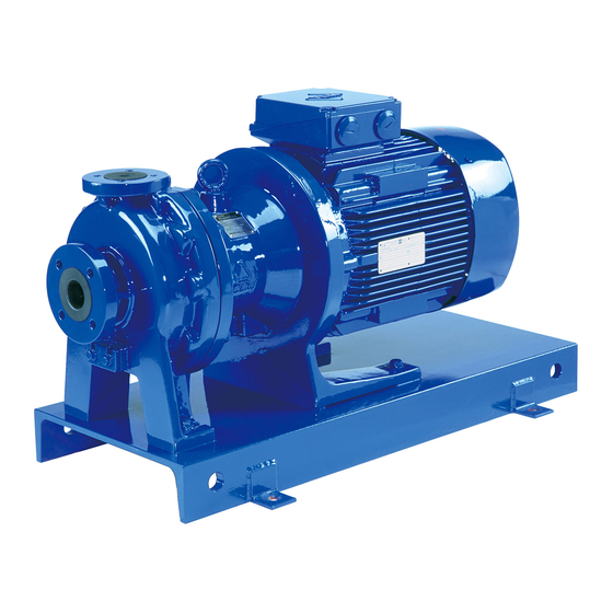
- Page 1 IWAKI Magnetic Drive Pump MDM Series (ISO Version) Instruction Manual Read this manual before use of product...
-
Page 2: Table Of Contents
Thank you for selecting IWAKI Magnetic Drive Pump MDM Series. This instruction manual, which is divided into five sections, namely "Safety", "Outline of Product", "Installation", "Operation" and "Maintenance", deals with the correct handling and operation procedures for the pump. To make maximum use of the pump and to ensure safe and long time operation of the pump, please read this manual thoroughly and carefully prior to operating the pump. -
Page 3: Safety Section
SAFETY SECTION For the Safe and Correct Handling of the Pump • Before use of the pump, read carefully this "Safety Section" to prevent accidents and to avoid the damage or loss of other assets. • Observe and abide by the instructions described in this "Safety Section". These instruc- tions are very important for protecting pump users or other persons from hazard or from loss of assets. - Page 4 Safety Section Warning • Magnet field danger The magnet drive pumps contain very strong magnets. The strong magnet field could adversely affect persons who are assisted by electronic devices such as pacemakers etc. • Always turn off power supply prior to maintenance works etc. Pay special attention so that no other operator turns on by mistake the power supply while someone is working on the pump.
- Page 5 Safety Section CAUTION • Attention to magnetic force This pump employs strong magnets. Special attention must be paid not to be injured by attracting force of magnets. Follow the procedure "Disassembling and Assembling" when the maintenance works are done. • Do not run pump dry Do not run pump dry (without liquid).
-
Page 6: Outline Of Product
OUTLINE OF PRODUCT ....... 1. Unpacking and inspection ..........2. Model code ....... 3. Conditions to be used ....4. Structure and names of parts - 4 -... -
Page 7: Unpacking And Inspection
CAPACITY (R/ / X) to your order. (2) If the product is not damaged or bolts are not MFG.NO. loosened during transportation. IWAKI CO.,LTD. (3) If accessories are attached. TOKYO JAPAN Standard accessories: Bolts for back pull-out M12 ◊ 100: 2pcs (M10 ◊... -
Page 8: Model Code
2. Model code MDM50 - 150 1 E KK F 075 I - D 2 w e r t y u i o !0 q Pump discharge bore Suction Discharge 25: 40 ◊ 25 32: 50 ◊ 32 40: 65 ◊... -
Page 9: Conditions To Be Used
The pump was made and shipped according to the information given to IWAKI. If the liquid condition is changed, ask and confirm IWAKI to use the pump without problem. -
Page 10: Structure And Names Of Parts
4. Structure and names of parts 500.3 554.5 554.6 554.3 908.1 100.1 400.1 901.5 901.6 901.3 903.1 400.3 122.2 554.4 901.4 314.1 314.2 500.2 122.1 554.2 400.2 901.2 500.1 554.1 901.1 554.7 314.4 314.3 901.7 Parts name Q'ty Parts name Q'ty 100.1 Front casing... -
Page 11: Installation
INSTALLATION ..........5. Installation ............6. Piping ........7. Electrical wiring - 9 -... -
Page 12: Installation
5. Installation Example of recommended piping q Discharge pipe w Discharge valve e Check valve r Pressure gauge t Motor y Pump u Flexible joint i Vacuum gauge o Suction pipe !0 Suction valve !1 Gate valve !2 Air vent piping !3 Pipe support 1. -
Page 13: Piping
6. Piping 1. Tightening of pipe flange Table below shows the bolt size and tightening torque for the connection of pipe flange to pump flange. Tightening torque is the figure when metallic flange and rubber gasket are used. Bolt size Tightening torque 78.4 N ⋅... - Page 14 3. Suction piping (1) Flooded suction Flooded suction is recommended. (2) Pipe diameter Pipe diameter should be larger than pump inlet bore. (3) Shortest piping Employ less bends and shortest piping length. (4) Straight piping Employ straight pipe just before pump inlet port. Pump inlet bore 50A or smaller : Straight pipe of 500 mm or longer Pump inlet bore 65A or larger : Straight pipe of 8 times as larger than inlet port (5) Air pocket in piping...
-
Page 15: Electrical Wiring
4. Discharge piping (1) Pipe diameter In case the discharge piping is long, the specified performance may not be obtained because of unexpected pipe resistance if the pipe diameter is the same as pump bore. Calculate the pipe resistance in advance to decide proper diameter of pipe. -
Page 16: Operation
OPERATION ...... 8. Precautions on operation ........ 9. Operation (Starting) ......... 10. Pump stopping - 14 -... -
Page 17: Precautions On Operation
8. Precautions on operation CAUTION • Never operate pump dry or with suction side valve closed. • Dry running possible type (model code CF type) can continuously run dry without damage one hour. However, dry running more than one hour or repeated dry running causes quick wear of rubbing parts. •... -
Page 18: Operation
9. Operation (Starting) 1. Fully close discharge valve and fully open suction valve. 2. Fill liquid into pump • In case of flooded suction, confirm if suction valve is fully opened. • In case of suction lift, prime to fill liquid into suction piping. 3. -
Page 19: Maintenance
Maintenance ........11. Troubleshooting ..... 12. Maintenance & inspection ....13. Disassembling & assembling ........14. Repair parts list ........... 15. Mass of pump - 17 -... -
Page 20: Troubleshooting
11. Troubleshooting Symptom on pump Check & countermea- Troubles Cause When disch. valve When disch. valve sures closed opened • Lack of priming • Stop pump and reple- Press. gauge & vac- Liquid can liquid uum gauge indicate nish pump with liquid not be sucked •... - Page 21 Symptom on pump Check & countermea- Troubles Cause When disch. valve When disch. valve sures closed opened • Too high actual • Check actual head of Pressure gauge & Pressure is high but D i s c h a r g e vacuum gauge indi- vacuum is normal.
-
Page 22: Maintenance & Inspection
12. Maintenance & inspection Warning • Magnetic force is very strong. Pay attention when you handle the magnet capsule or driving magnet so that fingers can not be injured by attraction of magnets. • The persons who are assisted by electronic devices such as pacemakers etc. are prohibited to approach the magnet capsule and drive magnet. -
Page 23: Disassembling & Assembling
2. Wear limit of bearing and spindle (Time to be replaced) Unit: mm Bearing inner dia. Spindle outer dia. Model New one Wear limit New one Wear limit MDM25-MM1 MDM25-MM2, MDM32, MDM40 MDM50 Note1. When the clearance between bearing inner dia. and spindle outer dia. exceeds 1 mm, replace by new ones. - Page 24 1. Disassembly of pump casing (1) Remove hex. bolts (909.1) and drain plate (122.1) to drain liquid inside. For the type without drain, disassemble the pump after the liquid inside is neutralized or the pump is cleaned by water. Warning If all the hex.
- Page 25 (7) Then, remove rear casing (158) from rear casing cover (159). If rear casing is hard to remove, remove it by turning. Pay attention not to drop the impeller (230)/magnet capsule (859) unit which is located in the rear casing. 2.
- Page 26 (3) Remove impeller fixing pin (942) of upper part of magnet capsule by pushing it by screw driver or like. (Ask IWAKI for removing impeller of PFA material type.) (4) Remove impeller (230) from magnet capsule (859). If it is hard to remove, slightly strike the impeller back side with plastic hammer.
- Page 27 4. Replacement of spindle (1) Spindle (210) is slightly pressed into rear casing (158). Pull out the spindle by a hand. If it is hard to pull it out, pull it out by shaking it right and left. (2) Wipe off the stain at spindle inserted part of rear casing and insert the spindle.
- Page 28 6. Assembling Assemble the pump in reverse procedures paying atten- tion to the following points. • Replacement of gasket Do not fail to replace the gasket by new one. Pay atten- tion so that it cannot be forgotten to be put or it can be mounted correctly without twist or bite.
-
Page 29: Repair Parts List
14. Repair parts list - 27 -... - Page 30 - 28 -...
- Page 31 - 29 -...
- Page 32 - 30 -...
- Page 33 MDM25 Impeller parts list Impeller Motor Q'ty/ Parts code No. Model Parts name size code power unit Impeller MDM0046 MDM0067 MDM0067 MDM0047 MDM0068 MDM0068 MDM0048 MDM0069 MDM0069 MDM0049 MDM0070 MDM0070 MDM0050 MDM0071 MDM0071 230+ Impeller a'ssy MDM0053 MDM0074 MDM0093 314.2 MDM0054 MDM0075 MDM0094...
- Page 34 MDM32/40/50 Impeller parts list Impeller Motor Q'ty/ Parts code No. Model Parts name size power unit Impeller MDM0215 MDM0239 MDM0239 MDM0216 MDM0240 MDM0240 MDM0217 MDM0241 MDM0241 MDM0218 MDM0242 MDM0242 MDM0219 MDM0243 MDM0243 MDM0220 MDM0244 MDM0244 MDM0221 MDM0245 MDM0245 230+ Impeller ass'y MDM0223 MDM0247 MDM0263...
- Page 35 Impeller Motor Q'ty/ Parts code No. Model Parts name size power unit 230+ Impeller/magnet 4.0kW MDM0303 MDM0331 MDM0352 310+ capsule ass'y 4.0kW MDM0304 MDM0332 MDM0353 314.2+ 4.0kW MDM0305 MDM0333 MDM0354 314.4+ 4.0kW MDM0306 MDM0334 MDM0355 859+ 4.0kW MDM0307 MDM0335 MDM0356 4.0kW MDM0308 MDM0336...
- Page 36 MDM50 Impeller parts list Impeller Motor Q'ty/ Parts code No. Model Parts name size power unit Impeller MDM0289 MDM0317 MDM0317 MDM0290 MDM0318 MDM0318 MDM0291 MDM0319 MDM0319 MDM0292 MDM0320 MDM0320 MDM0293 MDM0321 MDM0321 MDM0294 MDM0322 MDM0322 MDM0295 MDM0323 MDM0323 230+ Impeller ass'y MDM0380 MDM0408 MDM0436...
-
Page 37: Mass Of Pump
15. Mass of pump Output Total mass without motor & with Total mass without motor & without Model (kW) baseplate (kg) baseplate (kg) MDM25 - MM1 MDM25 - MM2 MDM32 MDM40 MDM50 - 35 -... - Page 38 IWAKI CO., LTD 6-6 Kanda-sudacho, 2-chome, Chiyoda-ku Tokyo 101-8558 Japan Tel: (81) 3 3254 2935 Fax: (81) 3 3252 8892 T382 99/7...
Need help?
Do you have a question about the MDM Series and is the answer not in the manual?
Questions and answers