Table of Contents

Related Manuals for IWAKI TC-X030V


Summary of Contents for IWAKI TC-X030V
- Page 1 D082UIE-00 PUMP OPERATION MANUAL For safety purposes please be sure to read and follow the instructions contained within this manual before pump installation and operation. TC-X030V TC-X050A TC-X050S TC-X050P TC-X050P-PP TC-X050V TC-X050D...
-
Page 2: Table Of Contents
Introduction Thank you for Purchasing our company Air Operated Double Diaphragm Pump. Diaphragm Pumps fall under the positive- displacement pump category. They are powered by compressed air and transfer liquids through the movement of 2 diaphragms connected by a center shaft. The pump runs through the use of an air switching mechanism which diverts air to each diaphragm in turn on a continuous fashion. -
Page 3: Important Items
Important Items For safe operation ● Before using the pump, be sure to read this document carefully, particularly the "warnings and cautions," and be fully familiar with the correct operating procedures. ● Within this document all the warnings and cautions will be indicated by the following symbols. If you ignore the warning described and operate the product in an improper manner, WARNING there is danger of serious bodily injury or death. -
Page 4: For Safety
For safety WARNING • When using compressed gas (hereinafter referred to as "compressed air") to drive this pump, be sure it is one of the following: 1)Compressed air supplied from an air compressor (To drive this product, use supply air with a minimum moisture content.) 2)Nitrogen (N2) gas The use of compressed air other than those mentioned above may cause air pollution, damage to the pump, or even an explosion. - Page 5 For safety WARNING • Before using this product, be sure you are familiar with the precautions regarding the fluid to be pumped, and verify the corrosion resistance of the parts that will come into contact with the fluid (wetted parts). NEVER use the product with any fluid against which it does not have sufficient corrosion resistance or with a fluid that poses a risk of explosion.
-
Page 6: For Safety
For safety CAUTION ・ If a diaphragm of this product is damaged, the supplied air may mix with the fluid or the fluid may flow into the main body (air- switching portion). If the air supply is inadequate or the pump is contaminated, do NOT operate the pump. ・... -
Page 7: Product Information
Product information 1.Specifications TC-X050 □ [NPT] TC-X030VT [NPT] Model AT , ST PT , PT-PP , VT, DT Liquid port Rc 1/4 [NPT 1/4] Material ・ Weight Table 1 0.2 ~ 0.7 MPa [30-100 psi] Operating pressure ※ 1 0.7 MPa [100 psi] Max discharge pressure 20 mL 15 mL... -
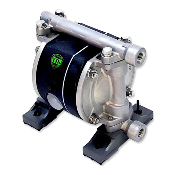
Page 8: Names Of Parts And Materials
Product information 3.Names of parts and materials Outside view Lift Point Out Manifold Ground Connection Point Ground Connection Point Out Manifold Out Chamber Out Chamber Airline Ball Valve Exhaust Port Supply Air Port In Manifold Base In Manifold Base : Discharge Port :... -
Page 9: Dimensions
Product information 4.Dimensions 050AT ・ ST 050PT ・ VT ・ DT / 030VT 050PT-PP LIQUID MODEL AIR INLET EXHAUST IN/OUT 050AT [5.87] [6.10] [5.87] [3.50] [0.59] [0.98] [4.41] [3.66] [4.13] [1.38] [3.58] [2.28] [2.24] [3.23] [4.33] 050ST 050PT [5.79] [6.06] [2.24] Rc1/4 Rc3/8... -
Page 10: Performance Curves
Product information 5.Performance curves 050AT ・ ST ・ PT ・ PT-PP ・ VT ・ DT 030VT Discharge volume (L/min) Discharge volume Air consumption Performance curve Liquid Temperature Correlation Graph NOTICE ・ The maximum safe working pressure of the pump depends on the liquid temperature. -
Page 11: Installation
Installation 1.Installing and connecting the pump ・ Decide where the pump should be installed and secure a suitable space (see Examples of installations A to D). Examples of pump installations Air supply D Exhaust A B C For optimal performance try to keep the suction lift as short as possible. To protect the diaphragms from abnormal damage or breakage, the inlet pressure must be kept below the following values: ※... - Page 12 Installation CAUTION ・ If the pump will be submerged into the liquid during operation, follow the steps below: * Verify the corrosion resistance of each component of the pump, and do NOT expose the pump to any fluid for which it does not have proper corrosion resistance.
-
Page 13: Recommended Liquid Piping Connection Diagram
Installation WARNING ・ If a diaphragm is damaged, fluid may be ejected along with the air from the exhaust port. In cases when the pump is positioned below the liquid so that hydraulic pressure is acting on the pump, pushing the diaphragms etc, if a diaphragm fails then fluid can flow out of the pump under gravity. -
Page 14: Recommended Air Piping Connection Diagram
Installation CAUTION ・ When fitting liquid hoses to the pump, make sure to use a sturdy hose that will not collapse when strong suction pressure is applied from the pump. Also make sure the hose has a sufficient pressure rating to cope with the required discharge pressure. ・... -
Page 15: Operation
Operation 1.Pump start up 1) Open the air valve in front of each piece of peripheral equipment, and adjust the supply air pressure with a regulator to within the permissible range. 2) Open the flow valve on the discharge side. 3) Press the RESET BUTTON, and then slowly open the air valve of the pump. -
Page 16: Releasing Pressure
Operation CAUTION ・ When the pump is shut down while pumping liquids containing slurry, particulate slurry matter contained in the liquid can settle and become deposited inside the bottom of the liquid chambers. If the pump is started again in the condition, the diaphragm may be damaged or the center disk may be overloaded, and this may cause damage such as bending or breaking of the center disk or center rod. -
Page 17: Maintenance
Maintenance ・ Daily maintenance checks A) Make sure the air filter drain is empty and working correctly. B) When using a lubricator, verify that the quantity of lubricating oil is sufficient. C) Make sure that there is no leakage of fluid from any hose connections or the pump body. D)... -
Page 18: Troubleshooting
Maintenance Troubleshooting Problem Probable Cause Actions to be taken The exhaust port (silencer) of pump is clogged with Check and clean the exhaust port or replace the Dirt or sludge. silencer. Start the compressor, open the airline ball valve and Air is not supplied air Regulator. - Page 19 Maintenance Troubleshooting Problem Probable Cause Actions to be taken Disassemble and check the pump and replace the The diaphragm is damaged Liquid leakage from exhaust port diaphragm. (silencer) The fastening nuts for the center disk are loose Disassemble and check the pump. Tighten the nuts. Disassemble and check the pump check and replace the The diaphragm is perforated cut or torn diaphragms as necessary.
- Page 20 memo - 19 -...
- Page 21 memo - 20 -...
-
Page 22: Limited Factory Warranty
Limited Factory Warranty - 21 -... - Page 23 - 22 -...
- Page 24 2015-4...
Need help?
Do you have a question about the TC-X030V and is the answer not in the manual?
Questions and answers