Table of Contents
Advertisement
Quick Links
Advertisement
Table of Contents

Related Manuals for IWAKI IX-C060 S6


Summary of Contents for IWAKI IX-C060 S6
- Page 1 Instruction manual Thank you for choosing our product. Please read through this instruction manual before use. This instruction manual describes important precautions and instruc- tions for the product. Always keep it on hand for quick reference. ©2015 IWAKI CO., LTD.
-
Page 2: Order Confirmation
Order confirmation Open the package and check that the product conforms to your order. If any problem or inconsistency is found, immediately contact your distributor. a. Check if the delivery is correct. Check the nameplate to see if the information such as model codes, discharge capacity and discharge pressure are as ordered. -
Page 3: Table Of Contents
Contents Order confirmation ............................2 Safety instructions ..............6 Warning ................................7 Caution ................................8 Precautions for use ............................ 10 Overview ...................12 Introduction ..............................12 Pump structure & Operating principle ...................... 12 Features ..............................13 Operational function ........................... 13 Manual mode ............................13 EXT mode .............................. - Page 4 Operational panel ............................. 23 Basic displays & Pump states ......................24 Identification codes ............................ 25 Pump ................................ 25 Installation ................26 Pump mounting ............................26 Pipework ..............................27 Piping layout ............................27 Drain port (Vent hole) ..........................28 Wiring ................................29 End terminals ............................29 Power voltage/Earthing ..........................30 Signal wire connection ..........................
- Page 5 IX-C150 S6 N ............................70 IX-C150 S6 FA ............................ 71 IX-C060 TC N ............................. 72 IX-C060 TC FA ............................ 73 IX-C060 S6 N ............................74 IX-C060 S6 FA ............................ 75 Specifications/Outer dimensions ......................76 Specifications ............................76 Pump ..............................76 Power cable ............................
-
Page 6: Safety Instructions
Safety instructions Read through this section before use. This section describes important information for you to prevent personal injury or property damage. ■ Symbols In this instruction manual, the degree of risk caused by incorrect use is noted with the follow- ing symbols. -
Page 7: Warning
Ne jamais modifier une pompe sous peine de causer un incident grave. Do not remodel Iwaki ne pourra en aucun cas être tenu responsable d’un incident ou de dégâts survenus à la suite d’une modification du dispositif. Wear protective clothing... -
Page 8: Caution
Risk of electric shock This pump is supplied with a grounding conductor and grounding-type attachment plug. To reduce the risk of electric shock, be certain that it is connected only to a properly grounded, grounding type receptacle. Risque de choc électrique Electrical La pompe est fournie avec un conducteur pour mise à... - Page 9 Spill precautions Ensure protection and containment of solution in the event of plumbing or pump damage (secondary containment). Déversement accidentel Prenez des mesures protectrices contre tout incident résultant d’un débit Requirement trop important de la pompe ou d’une casse de tuyauterie. Do not use the pump in a wet location The pump is not waterproof.
-
Page 10: Precautions For Use
Precautions for use • Electrical work should be performed by a qualified electrician. Otherwise, personal injury or property damage could result. Le raccordement électrique de la pompe doit être effectué par du person- nel qualifié sinon, il pourrait y avoir un dommage corporel ou incorporel. Caution •... - Page 11 • Use measures to keep the pump connections free from stress. Weight and thermal expansion/contraction of the piping can stress connection points. La pompe ne doit pas être soumise à des effets éventuels de dilation ou de contraction du pipe dus à un stress thermique. Caution •...
-
Page 12: Overview
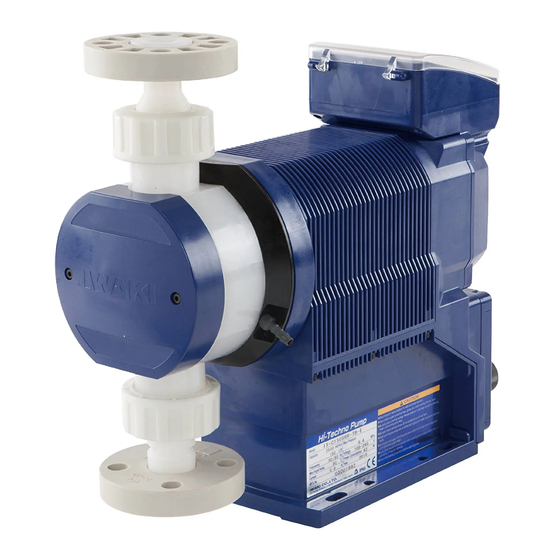
Overview Pump characteristics, features and part names are described in this section. Introduction Pump structure & Operating principle The IX series are diaphragm pumps with a brushless DC (BLDC) motor and feature a high turndown ratio & automatic controls. Principle of operation In the IX series design, a BLDC motor rotation controls the flow rate. -
Page 13: Features
Features ● High turndown ratio Use of a BLDC control motor enables accurate control with a wide turndown ratio. ● High repeatability Highly-efficient valve design and accurate discharge-/suction-speed controls assure the high repeatability of chemical dosing (±1%). ● Energy-saving design Use of helical gears and an assist spring reduces power consumption by 70% compared to our existing me- tering pump designs (spring back). -
Page 14: Ext Mode
EXT mode ■ Analogue proportional control ANA. P (analogue preset) programming (see page 42 & 54) Select a proportional control pattern. 4 - 20mA, 20 - 4mA, 0 - 20mA and 20 - 0mA are available. During opera- tion, the display shows the current flow rate. To show the current value, push the key. - Page 15 ANA. V (analogue variable) programming (see page 42 & 54) The pump increases/decreases a stroke/flow rate in proportion to 0-20mA. Determine the operational behav- iour by programming two set points and choosing one of the LINEAR, BOX and LIMIT patterns. To show the current value, push the key.
-
Page 16: Pulse Control
■ Pulse control (see page 42 & 54) The flow rate is automatically controlled by the flow volume (ml) per pulse and the pulse signal frequency from a flow meter. * It takes about 10 pulses for the IX to catch up with the change of the frequency. 10Hz 10Hz Pulse signal... - Page 17 Example of use: Chemical dosing in a production line system Pump Supply tank Pulse signal Proximity switch When the buffer is ON: Every time the external pulse signal is inputted, the programmed flow volume per pulse is accumulated (max 65535 pulses) even when the pump is activated for the earlier pulse input. *The control stops immediately and all the pulse accumulation is cleared when the key is pushed once.
-
Page 18: Interval Batch Control
■ Interval batch control (see page 42 & 54) To make an interval batch control, set a date and time interval and the flow volume. The IX discharges the pro- grammed flow volume at a set interval. In the diagram below, the interval is set to 1 hour. * The pump runs at the MAN speed. -
Page 19: Stop Functions
STOP functions ■ STOP function (see page 45) The start/stop of operation can be controlled by the signal from a level sensor. The operation LED changes from green to red colour when the pump is receiving the Pre-STOP signal from a level sensor in operation. See page 32 "STOP IN"... -
Page 20: Protective Functions
Protective functions ■ Interlock function (see page 32 & 47) Interlock function works in the same way as the STOP function but uses a preference circuit. Use this function for emergency stop. ■ Diaphragm rupture detection (see page 45) The pump stops right after a built-in sensor detects a leak in the compartment at the back of the diaphragm. In this condition, the operation LED lights in red colour. -
Page 21: Alarm Output Function
■ Alarm output function (see page 47) Enable or disable the output of the batch completion, STOP, Pre-STOP, interlock, diaphragm rupture detection, pressure overload detection, and/or drive error detection functions which is preset to the Alarm OUT 1 and 2, or the output of the volume proportional pulse preset only to the Alarm OUT 2. -
Page 22: Part Names
Part names Pump Control unit Used for the start/stop of the pump and operation control/program- ming. See next page for detail. Unhook the cover to open it. Push down until it clicks once to close it. Outlet Bolt cover Take out the cover to remove the pump head. -
Page 23: Operational Panel
Operation panel Display An operational status, a selected mode and programmed values are shown here. Start/Stop key Used for starting/stopping the pump operation or moving back to the MAN/ EXT selection. ESC key Used for cancelling pro- gramming and moving back to a previous menu. -
Page 24: Basic Displays & Pump States
■ Basic displays & Pump states Operation LED Operation LED Operation LED ALARM LED Display lights in red lights in green lights in orange lights in red Operation in ― ― ― manual mode Operation in EXT ― mode (Analogue ―... -
Page 25: Identification Codes
Identification codes Each code represents the following information. Pump IX - C 150 TC N - TB a. Series name b. Drive unit c. Pump unit (Max flow) 150 : 150 [L/H] 060 : 60 [L/H] d. Wet end materials Code Pump head Ball valve... -
Page 26: Installation
Installation This section describes the installation of the pump, piping and wiring. Read through this section before work. Points to be observed Observe the following points when installing the pump. • Risk of electrical shock. Be sure to turn off power to stop the pump and related devices before service is performed. -
Page 27: Pipework
Pipework ■ Piping layout Flooded suction application Suction lift application Accumulator/Chamber Accumulator/Chamber Pressure gauge Pressure gauge Relief valve Relief valve Back pressure valve Back pressure valve Air vent/ drain valve Air vent/drain valve Pump Calibration cylinder Calibration Pump cylinder Tank Tank NOTE •... -
Page 28: Drain Port (Vent Hole)
Drain port (Vent hole) Leaked liquid drains through the drain port at the time of accidental diaphragm rupture. Use an appropriate chemically-resistant tube to the port to safely collect the liquid. NOTE • Do not plug the drain port. The port functions as a vent hole to keep the pressure behind the diaphragm back atmospheric. -
Page 29: Wiring
Wiring Wiring for power voltage, earthing and external signals. Points to be observed Observe the following points during wiring work. • Electrical work should be performed by a qualified electrician. Always observe applica- ble codes or regulations. • Do not apply power other than that specified on the nameplate. Otherwise, failure or fire may result. -
Page 30: Power Voltage/Earthing
Power voltage/Earthing Points to be checked • Check that power voltage is turned off. Insert the plug all the way seated in a socket. NOTE • Do not share a power source with a high power device which may generate a surge voltage. Otherwise an electronic circuit may fail. -
Page 31: Signal Wire Connection
Precautions for ON-OFF control by a mechanical relay The control unit is equipped with a CPU. To ensure the CPU to work properly, always start/stop the pump by the STOP signal for ON-OFF control. Try not to turn on and off the main power. -
Page 32: Ext In
■ EXT IN To make pulse-, batch-, interval batch- and analogue-control operation or to activate interlock function, connect signal wires to the EXT terminals via the DIN 5-pin connection. When using an open collector: Pay attention to polarity. Pulse (1) and Interlock (2) are plus (+), and COM (4) is minus (-). When using analogue control: Pay attention to polarity. -
Page 33: Aux In/Analog Out
■ AUX IN/Analog OUT To activate the AUX function or to use the analogue output, connect signal wires to the AUX terminal or the 4-20mA output terminal via the DIN 5-pin connection. When using an open collector (for AUX IN): Pay attention to polarity. -
Page 34: Operation
Operation This section describes pump operation and programming. Run the pump after pipework and wiring are completed. Before operation First check piping and wiring are correct. And then make commissioning before starting op- eration. Points to be checked Before operation, check if: •... -
Page 35: Commissioning
Commissioning Always make commissioning when first mounting the pump in your system or resuming operation after a long period of stoppage. Open an air vent and a suction line. Do not open a calibration line if any. Air vent valve Open Close Open... -
Page 36: Perform A Calibration
Perform a calibration Periodically make calibration to monitor an accurate flow through control display. The pump is calibrated by pumping clean water at the maximum operating pressure before shipping (in the absence of a designation by a user), however, make calibration again in an actual operating condition as necessary. -
Page 37: Calibration Process
Calibration process Obtain accurate flow volume per shot (e.g. about 16ml/shot for the C150 type, about 6ml/shot for the C060 type) by dividing the delivered liquid volume by the number of strokes. Fill a calibration cylinder with liquid. Open a calibration line to lead liquid from a supply tank to a calibration cylinder. And then close the suc- tion line and measure liquid volume in the cylinder. - Page 38 Start calibration operation. Push the Enter key after setting the number of strokes. The pump starts the countdown. The pump starts to run for the set number of Pump strokes as it comes to zero. starts Pump stops Measure liquid volume in the calibration cylinder again. Enter how much liquid has reduced.
-
Page 39: Operation Programming
Operation programming The setting is made with the controller. The pump behaviour differs with each control mode. Menu Control mode/Function Parameter Default Mode se- MAN/EXT lection Analog preset control 0 - 20mA/ 4 - 20mA/ 20 - 0mA/ 20 - 4mA 4-20mA SP1 current 0.0 - 20.0mA... -
Page 40: Programming Flow
Programming flow Power ON MAN/EXT selection Wait state Menu screen EXT mode MAN mode Operation EXT mode MAN mode keys to scroll. * See page 41 for setting at each menu. * To revert back to the default setting with the pump calibrated, turn on power while pressing the ESC key. Operation programming... -
Page 41: Menu Screen
Menu screen Push the MENU key in the MAN/EXT selection mode and call up the menu screen. Use the right and left keys to scroll through each menu item and then push the Enter key to make a selection. Pushing the MENU key again or ESC key in the menu screen, the previous mode will be recalled. -
Page 42: Ext Mode Selection
■ EXT mode selection Mode selection screen Analogue preset Analogue variable key to confirm key to return to menu screen Pulse control key to scroll key to change values Batch control Interval batch control Profibus control Mode setting screen Analogue preset control <To next page>... - Page 43 Analogue vairable control SP1 current setting to change the value SP1 flow rate setting to change the value SP2 current setting to change the value SP2 flow rate setting to change the value Behavioural pattern selection to select the pattern Pulse control Set flow volume per pulse.
-
Page 44: Calibration
Interval batch control Set “Day”. Set “Hour”. Set “Minute”. Set a flow rate. Profibus control Set an address. ■ Calibration *See page 37 "Calibration process" for detail. key to confirm key to return to menu screen key to select key to change values Operation programming... -
Page 45: Signal Input Setting
■ Signal input setting Function selection screen STOP function Pre-STOP function key to confirm key to return to menu screen Interlock function key to scroll key to change values Diaphragm rupture detection Function setting screen STOP function Closed=Pump OFF : Pump stops running at contact input. -
Page 46: Analogue Output Setting
Diaphragm rupture detection Disable : Rupture detection is not used. Enable : Rupture detection is used. ■ Analogue output setting Function selection screen SP1 current setting to change the value key to confirm SP1 flow rate setting key to return to menu screen to change the value key to scroll key to change values... -
Page 47: Alarm Output Setting (Out 1)
■ Alarm output setting (OUT 1) <Mechanical relay> Output selection screen Batch completion STOP function Drive error key to confirm key to return to menu screen key to scroll Pre-STOP function Overload detection key to change values Interlock function Diaphragm rupture detection Output setting screen Batch completion Disable : OUT1 is inactive. - Page 48 Pre-STOP function Disable : OUT1 is inactive. Enable : OUT1 is activated at input of Pre-STOP signal. Interlock function Disable : OUT1 is inactive. Enable : OUT1 is activated at input of interlock signal. Diaphragm rupture detection Disable : OUT1 is inactive. Enable : OUT1 is activated at input of the detection signal.
-
Page 49: Alarm Output Setting (Out 2)
■ Alarm output setting (OUT 2) <PhotoMOS relay> Output selection screen Volume proportional pulse Batch completion key to confirm Drive error key to return to menu screen key to scroll STOP function key to change values Overload detection Pre-STOP function Interlock function Diaphragm rupture detection Output setting screen... -
Page 50: Data Logging
■ Data logging Data logging screen Operating time Total flow volume key to confirm Software version key to return to menu key to scroll Powered-on time Press 3 sec to delete data Number of ON/OFF 3 sec Return to a previous screen. *A selected data will be cleared except the version information. -
Page 51: Programming Of Other Functions
■ Programming of other functions Other selection screen Suction speed Language selection Max flow rate key to confirm Pin number entry key to return to menu screen AUX speed key to scroll Flow rate unit key to change values Diaphragm position Output 2 logic Buffer... - Page 52 Max flow rate Set a flow rate. AUX speed Set a flow rate. Diaphragm position MAX OUT Pos. : The diaphragm comes to the top dead point. MAX IN Pos. : The diaphragm comes to the bottom dead point. * Either one of the above indication keeps flashing as long as the diaphragm is at either end.
- Page 53 Output 1 logic Set the output 2 logic as necessary. Flow rate unit Pin number entry key to change values key to move through each digit key to confirm Language selection Operation programming...
-
Page 54: Operation
Operation Read this section before operation. Manual operation Run or stop the pump by keypad operation. Supply the rated power voltage to the pump. The operation LED lights in red colour, and a previous mode at the last shutoff returns. * The pump enters the MAN/EXT selection mode when turning on power with a default setting. -
Page 55: Aux Function
Push the right key to select "EXT" and the Enter key to enter that choice. Waiting state display *The pump enters the analogue preset, analogue variable, pulse, batch or interval batch mode. Push the start/stop key to start operation. The pump runs along with operation program- ming and the external signal. -
Page 56: Keypad Lock
Keypad lock Keypad lock can be active for the prevention of erroneous key operation. NOTE • Any key operation is not acceptable when the keypad lock is active. In an emergency, however, pressing the start/stop key for two seconds, the pump enters a wait state and stops running. Enter the PIN number to release this state before resuming operation. -
Page 57: Maintenance
Maintenance This section describes troubleshooting, maintenance, wear part replace- ment, exploded views and specifications. Points to be observed Observe the following points during maintenance work: • Observe instructions in this manual for maintenance, inspection, dismantlement and as- sembly. Do not dismantle the pump beyond the extent of the instructions. •... -
Page 58: Troubleshooting
Troubleshooting First check the following points. If the following measures do not help remove problems, con- tact your nearest distributor. ■ Pump States Possible causes Solutions The pump does not run Power voltage is too low. • Observe the allowable voltage range of ( the operation LED 90-264VAC. -
Page 59: Error Messages
Error messages Take measures below when any of the error messages appears during operation. Contact us or your nearest distributor as necessary. Error messages Possible causes Measures • Check a discharge line for clogging and re- Pressure overload protection is move it as necessary. -
Page 60: Wear Part Replacement
Wear part replacement To run the pump for a long period, wear parts need to be replaced periodically. It is recommended that the following parts are always stocked for immediate replacement. Contact your nearest distributor for detail. Precautions • Solution in the discharge line may be under pressure. Release the pressure from the discharge line before disconnecting plumbing or disassembly of the pump to avoid solu- tion spray. - Page 61 Pump head Parts # of parts Estimated life C150 Retainer 8000 hours (IX0015) (IX0051) (IX0048) Valve set (IX0047) (TC type) 2 sets 8000 hours (IX0049) IX0069 (IX0051) (IX0053) (IX0051) (IX0052) (IX0048) Valve set (IX0047) (TE type) 2 sets 8000 hours (IX0050) IX0070 (IX0052)
-
Page 62: Before Replacement
• Use care handling the valve set. Do not drop it especially when the suction pipe is removed from the pump inlet. • Remove the IX-C060 TC/TE nuts while holding the adapter with a spanner. IX-C150 TC/TE IX-C060 TC/TE IX-C150 S6 IX-C060 S6 Remove Adapter Remove the the bolt valve cap... -
Page 63: Diaphragm Replacement
Take out valve sets from the pump head and take them apart to replace worn parts as necessary. Clean the pump head as necessary. Valve set Reassemble and remount the valve sets in the pump head. Observe the mounting order and direction of valve set components. See the exploded view at each model. - Page 64 Remove the bolt cover by a 3mm hexagon wrench (TC/TE types). Hexagon wrench Bolt cover Use a 13mm spanner to remove the six M8 bolts and de- tach the pump head with a reinforcing plate. Pump head Reinforcing plate (TC/TE types) Extend the pump shaft by keypad operation.
- Page 65 Clean the retainer or replace it with a new one. Apply the grease (Dow Corning Toray MOLYKOTE HP-500) on its surface and the screw burning protective agent to the shaft ® of a new diaphragm. Fit a new diaphragm and the retainer into the pump shaft. Slide the retainer, dome end first, onto the diaphragm shaft.
- Page 66 Fix the bolt cover by the hexagon wrench (TC/TE types). Connect pipes to the fittings and then tighten the nuts. NOTE Check if the valve set mounting direction is correct. Both the valve sets must be oriented to the same direction. Valve set Go back to the waiting state.
-
Page 67: Exploded View
Exploded view Pump head, Drive unit & Control unit Do not dismantle the pump beyond the extent shown in the diagram below. Pump Valve set Pump head Bolt cover Retainer Drive unit Diaphragm Valve set Reinforcing plate Pump head *Pump head material and size differ with models. Exploded view... -
Page 68: Pump Head
Pump head ■ IX-C150 TC N Part names # of parts Pump head Valve Valve guide Valve seat Out seat holder In seat holder O ring O ring Hex socket head bolt Hexagon head bolt Spring washer Bolt cover Reinforcing plate Diaphragm Retainer plate Fitting... -
Page 69: Ix-C150 Tc Fa
■ IX-C150 TC FA Part names # of parts Pump head Valve Valve guide Valve seat Out seat holder In seat holder O ring O ring Hex socket head bolt Hexagon head bolt Spring washer Bolt cover Reinforcing plate Diaphragm Retainer plate Flange unit Exploded view... -
Page 70: Ix-C150 S6 N
■ IX-C150 S6 N Part names # of parts Pump head Valve Valve guide Valve seat Valve gasket Hexagon head bolt Spring washer Diaphragm Retainer plate Setting flange Fitting Hexagon head bolt Exploded view... -
Page 71: Ix-C150 S6 Fa
■ IX-C150 S6 FA Part names # of parts Pump head Valve Valve guide Valve seat Valve gasket Hexagon head bolt Spring washer Diaphragm Retainer plate Flange unit Hexagon head bolt Exploded view... -
Page 72: Ix-C060 Tc N
■ IX-C060 TC N Part names # of parts Pump head Valve Valve guide Valve seat O ring Seat holder Adapter Hex socket head bolt Hexagon head bolt Spring washer Plain washer Bolt cover Reinforcing plate Diaphragm Retainer plate Fitting Exploded view... -
Page 73: Ix-C060 Tc Fa
■ IX-C060 TC FA Part names # of parts Pump head Valve Valve guide Valve seat O ring Seat holder Adapter Hex socket head bolt Hexagon head bolt Spring washer Plain washer Bolt cover Reinforcing plate Diaphragm Retainer plate Flange unit Exploded view... -
Page 74: Ix-C060 S6 N
■ IX-C060 S6 N Part names # of parts Pump head Valve Valve guide Valve seat Valve gasket Valve cap Hexagon head bolt Spring washer Plain washer Diaphragm Retainer plate Fitting Exploded view... -
Page 75: Ix-C060 S6 Fa
■ IX-C060 S6 FA Part names # of parts Pump head Valve Valve guide Valve seat Valve gasket Valve cap Hexagon head bolt Spring washer Plain washer Diaphragm Retainer plate Flange unit Exploded view... -
Page 76: Specifications/Outer Dimensions
*Allowable power voltage deviation: Within ±10% of the rated range *Ambient humidity: 30-90%RH (non condensing) * When running the IX-C150 S6 at or below 1.0L/H or the IX-C060 S6 at or below 0.4L/H, an actual flow rate may not meet a target rate. -
Page 77: Control Unit
■ Control unit MAN (Manual) A flow rate is set with (Up) and (Down) keys. Analogue preset 4-20/0-20/20-4/20-0mA (proportional control of a flow by current patterns) Analogue variable 0-20mADC (proportional control of a flow by user-settable two points ) 0.00625mL/PLS - 120mL/PLS (C060) Pulse control* 0.01560mL/PLS - 300mL/PLS (C150) Operation... -
Page 78: Outer Dimensions
Outer dimensions ■ IX-C060/-C150 TC/TE N-TB Center of inlet/outlet IX-C150 TC/TE N IX-C060 TC/TE N 339.5 102.5 Specifications/Outer dimensions... -
Page 79: Ix-C060/-C150 Tc/Te Fa-Tb
■ IX-C060/-C150 TC/TE FA-TB Center of inlet/outlet IX-C150 TC/TE FA ─ ─ IX-C060 TC/TE FA ─ 339.5 ─ 102.5 Specifications/Outer dimensions... -
Page 80: Ix-C060/-C150 Tc/Te N-Rf
■ IX-C060/-C150 TC/TE N-RF (115) Center of inlet/outlet IX-C150 TC/TE N IX-C060 TC/TE N 339.5 102.5 Specifications/Outer dimensions... -
Page 81: Ix-C060/-C150 Tc/Te Fa-Rf
■ IX-C060/-C150 TC/TE FA-RF (115) Center of inlet/outlet IX-C150 TC/TE FA ─ ─ IX-C060 TC/TE FA ─ 339.5 ─ 102.5 Specifications/Outer dimensions... -
Page 82: Ix-C060/-C150 S6 N-Tb
■ IX-C060/-C150 S6 N-TB Center of inlet/outlet IX-C150 S6 N 333.5 96.5 IX-C060 S6 N Specifications/Outer dimensions... -
Page 83: Ix-C060/-C150 S6 Fa-Tb
■ IX-C060/-C150 S6 FA-TB Center of inlet/outlet IX-C150 S6 FA ─ 333.5 ─ 96.5 IX-C060 S6 FA ─ ─ Specifications/Outer dimensions... -
Page 84: Ix-C060/-C150 S6 N-Rf
■ IX-C060/-C150 S6 N-RF (115) Center of inlet/outlet IX-C150 S6 N 333.5 96.5 IX-C060 S6 N Specifications/Outer dimensions... -
Page 85: Ix-C060/-C150 S6 Fa-Rf
■ IX-C060/-C150 S6 FA-RF (115) Center of inlet/outlet IX-C150 S6 FA ─ 333.5 ─ 96.5 IX-C060 S6 FA ─ ─ Specifications/Outer dimensions... - Page 88 Holland / IWAKI Europe GmbH (Netherlands Branch) U.K. / IWAKI Pumps (U.K.) LTD. China (Guangzhou) / GFTZ IWAKI Engineering & Trading Co., Ltd. TEL: +31 74 2420011 FAX: +49 2154 9254 48 TEL: +44 1743 231363 FAX: +44 1743 366507...
Need help?
Do you have a question about the IX-C060 S6 and is the answer not in the manual?
Questions and answers