Table of Contents
Advertisement
Quick Links
Advertisement
Table of Contents

Related Manuals for STI Alert Point


Summary of Contents for STI Alert Point
- Page 1 Alert Point Installation Guide & User Manual...
-
Page 2: Table Of Contents
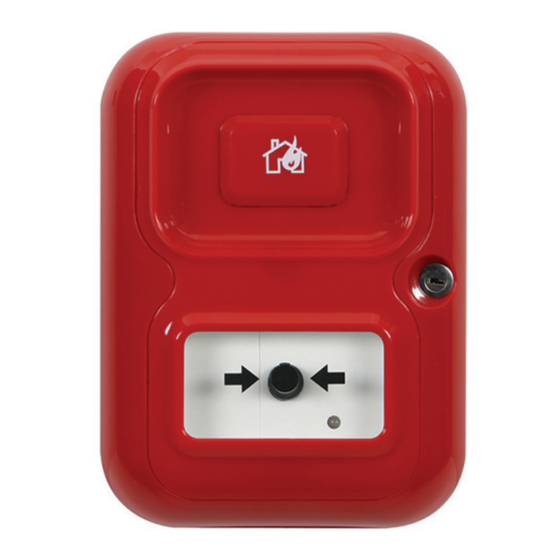
Available in a variety of colours, the Alert Point can be used for a wide range of applications such as fire, intruder, panic, evacuation, assist or general alarm. It also... -
Page 3: Box Contents & Key Components
Box Contents & Key Components Contents 1. Reversible Mounting Plate (x1) 2. Chassis (x1) 4. Installation Kit 3. Front Cover (x1) 4. Installation Kit (x1) Reset Key Master Key 1” Screws (x4) Rawlplugs (x4) 1. Reversible Mounting Plate 2. Chassis Integral Sounder Master Key Switch Cylinder... -
Page 4: Alert Point Installation
Alert Point Installation Step 1. Install the Reversible Mounting Plate The reversible mounting plate can be Mark the 4 fixing points (as shown) and installed in any orientation; depending on install using the screws and Rawl plugs the required conduit entry and exit points. - Page 5 Depress the operating element. A warning indicator drops into view, the unit will alarm and the LED will turn red when the Alert point is activated. Step 7. Reset the unit Simply insert the reset A quick turn of the key and the...
-
Page 6: Removal Of The Front Cover
Removal of the front cover Using the 2 pips on the reset key provided, push firmly into each of the 4 corner clips individually, releasing them, whilst at the same time gently pulling the cover away from the remainder of the unit. Need technical support? Call us on +44 (0)1527 520 999... -
Page 7: User Manual
User Manual... -
Page 8: Programmable Features
8. Networking the Alert: DIL Switch No SW12 If this switch is ‘ON’ the Alert Point expects to be connected to another Alert Point otherwise a fault is indicated. If the switch is ‘OFF’ the Alert Point will not expect to be connected to another Alert Point. -
Page 9: Other Features
Other Features Integral sounder volume: The Alert Point has 2 volume settings – High and Low: this is determined by the position of the jumper connector configuration show below. High: Jumper between centre pin and bottom pin (factory setting) Low: Jumper between centre pin and top pin... -
Page 10: Installing A 12-30 Vdc Power Supply
Installing External 12-30 VDC Power Supply External Power + External Power - Step 1. Ensure that the unit is switched ‘OFF’. Step 2. Insert the external power wires into the correct terminals. Step 3. Connect the 9 VDC battery. The battery must be fitted as it will become a backup if there is a power failure. -
Page 11: Installing External Sounders
Step 6. Test: When the operating element is depressed, the unit will go into alarm condition: the externally installed sounders should now sound. Step 7. Reset the Alert Point using the reset key, all sounders should now silence. Please note: If the ‘Auto Reset’ is disabled (DIL switch SW11 ‘OFF’) the sounders will continue to sound until the master Key switch is turned ‘OFF’. -
Page 12: Installing External Strobes / Beacons
50 metres. Optional Internal Beacon An optional extra (not supplied as standard) for the Alert Point is the capacity to incorporate an internal beacon – this can provide for those who may be audibly impaired. -
Page 13: Installing External Detectors
It is recommended that the maximum wiring length from the detector terminals on the Alert Point to the final detector in the loop, should not exceed more than 50 metres. Need technical support? Call us on +44 (0)1527 520 999... -
Page 14: Networking The Alert Point
Resetting the networked Alert Points, can only be done by manually resetting the original activated unit (e.g. Alert Point 1 from this test) using the reset key. This will return both units back into ‘standby ‘condition. Step 8. The above test should now be reversed. - Page 15 Step 6. Turn all the units ‘ON’ using the master key switch. Step 7. TEST Alert Point 1, depress the operating element. This will send the unit into alarm condition, causing the activation flag to drop into view, the LED to flash red and the integral alarm to sound.
-
Page 16: Networking Features
In the example above the ‘Network In’ connection is lost on Alert Point 2. Resulting in: 1. Alert Point 2 - The LED will flash red and a warning double beep will sound every 90 seconds. 2. Alert Point 1 - cannot trigger Alert Point 2 into alarm condition: the signal is lost to the ‘Network In’... -
Page 17: Troubleshooting
Check installation The Alert Point is constantly in Operating element depressed Reset using reset key `alarm' condition Networked - The linked Alert Point is in `alarm' Reset the `networked' Alert Point condition Tamper alarm activating Check installation Externally fitted detectors triggering Alert Point Check linked units are not alarming LED red &... -
Page 18: Pcb Terminal Diagram
All detectors need to be hard wired on a N.O. loop, Power sourc have their own power supply and an end of line 5V6 Using the Alert Point as a Manual Call Point Standby cur Zener diode fitted (supplied with the unit). -
Page 19: Dil Switch Settings - Programmable Features
DIL Switch Settings – Programmable Features Important: Changes made to any DIL switch settings will only take effect after the Alert Point has been reset using the master key switch. Fea tures D I L S w itc h S etting... - Page 20 Worcestershire • B60 3DR • England Tel: 248 673 9898 • Fax: 248 673 1246 Tel: +44 (0)1527 520 999 • Fax: +44 (0)1527 501 999 Email: info@sti-usa.com • Web: www.sti-usa.com Email: info@sti-emea.com • Web: www.sti-emea.com Alertpoint Installation rev 1_Jan2017...
Need help?
Do you have a question about the Alert Point and is the answer not in the manual?
Questions and answers