Table of Contents
Advertisement
Quick Links
Features
·
Helps prevent unauthorized exits/entries through doors.
·
Easy to install. Warning sound when turning on (two flashes/beeps) and off
(one flash/beep).
·
Add warning in second language with provided labels (21 languages).
·
Select volume, alarm duration and delay settings.
·
Mount on top, right, left or next to almost any door.
·
Select on-site whether to use an alarm or annunciator.
·
Low battery detection, beep and flashes.
·
Alarm sounds and high power LED light flashes when activated.
·
Dry contact Form C relay.
·
Protect anything such as cabinet, extinguisher, etc. with an external reed or
any mechanical switch.
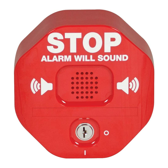
Exit Stopper
STI-6400 Series
Rely on STI
- 1 -
®
®
Advertisement
Table of Contents

Related Manuals for STI Exit Stopper STI-6400 Series


Summary of Contents for STI Exit Stopper STI-6400 Series
- Page 1 · Alarm sounds and high power LED light flashes when activated. · Dry contact Form C relay. · Protect anything such as cabinet, extinguisher, etc. with an external reed or any mechanical switch. Rely on STI ® - 1 -...
-
Page 2: Warranty Information
All units are recommended for indoor use only. Unit must be tested periodically to verify the life of battery. STI recommends you change the 9 Volt battery twice a year. To hear alarm when normal work environment is loud, may need to purchase remote horns. When purchasing a remote unit (STI-6403 or STI-6404) you will need to periodically test the connections to make sure audibles function at a sound level to alert staff. -
Page 3: Specifications
Alarm Current 50mA at 95 dB/ 200 mA at 105 dB * Power source for the STI-6403 and STI-6404 Remote Horn uses a separate power source from the STI-6400 alarm. The Remote Horn contains an internal 9 volt battery. Horn operates when the Form C contact at main unit is activated on alarm. -
Page 4: Switch Settings
Circuit Board Set-up Remote Power Switch Settings (defaults shown) Form C Relay All models are shipped with jumper across RS2 terminals for use with one reed switch. If using second reed KEYSW switch, remove jumper wire and insert second reed switch. JUMPER WIRE Figure 1 TO MAGNETIC SWITCH... -
Page 5: Test Alarm
Save the tamper wrench for future service and battery replacement (Fig. 2). 3. Connect battery. 4. Place magnet next to reed switch. Note: for STI-6402 and STI-6404 models, place magnet next to reed switches 1 & 2. 5. Turn the key switch to the ON position. - Page 6 1. If not using extra reed switch, leave jumper wire across terminals RS2 on terminal block. 2. Determine length needed for reed switch wires. STI provides 1 reed KIT-E06402 switch with 6 ft. wires. Cut to desired REED SWITCH OPTIONAL: (RS2) length.
-
Page 7: Mounting Options
STI-6404 Double Door with Remote Horn Install Notes The STI-6404 is a combination unit for double doors with a remote horn. Reference the installation instructions for the main unit, the STI-6402 and the STI-6403 for complete installation. STI-6405 Exit Stopper with Momentary Reset The STI-6405 uses a momentary switch. - Page 8 ADDTIONAL REED SWITCH KIT-E06402 Taylor House • 34 Sherwood Road • Bromsgrove Worcestershire • B60 3DR • England • Tel: +44 (0)1527 520 999 Fax: +44 (0)1527 501 999 • info@sti-emea.com • www.sti-emea.com Inst. 6400 OCT2017 Subject to change without notice.
Need help?
Do you have a question about the Exit Stopper STI-6400 Series and is the answer not in the manual?
Questions and answers