Advertisement
Quick Links
Mounting hardware included with
flush mount version
(2) #6-32 x 1.0 in.
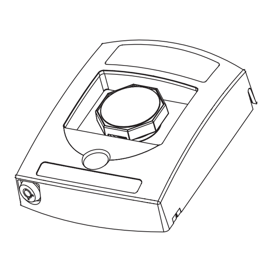
Push button operating element
(OPTIONAL CAMERA)
See camera operation manual
Camera model surface mount version shown
FRAME MOUNTS TO:
MOUNTING HOLE KEY
SCREW SIZE REQUIRED
• Single gang box
#10 x 3/4 in. pan-sms
KIT-GLR-BB-R
• Double gang box
Four square box
#8-32 x 1.0 in. machine screw
• Four square box
Double gang box
#6-32 x 1.0 in. machine screw
• 60.3 mm European box
60.3mm European box
M3.5 x 35mm machine screw
• KIT-GLR-BB-R
Single gang box
#6-32 x 1.0 in. machine screw
RESET
1.75 in.
(44.5 mm)
Key
CR123A Lithium battery
Volume Jumper
*Mylar
ad
Screw
Button
MOUNTING HOLE KEY
4.12 in.
KIT-GLR-BB-R
Volume Jumper
HI
LOW
(104.8 mm)
d
Four square box
HIGH
Double gang box
2.06 in.
(default)
60.3mm European box
5.43 in.
(52.4 mm)
Single gang box
(137.8 mm)
2.9 in.
(73mm)
HI
LOW
LOW
*Remove Mylar for sounder activation
5.43 in.
(137.8 mm)
A
.9 in.
3mm)
USA
FRAME MOUNTS TO:
• Single gang box
• Double gang box
• Four square box
• 60.3 mm European box
• KIT-GLR-BB-R
Installation Components
When anchors are used drill
FRAME MOUNTS TO:
3/16 dia. holes 1-1/4 in. deep
• Single gang box
1/2 in. NPT Thread
• Double gang box
When anchors are not used drill
• Four square box
Drill (4) 11/64 in. holes
7/64 dia. 1-1/4 in. deep
4.125 in.
• 60.3 mm European box
for general wall mount
(104.77 mm)
• KIT-GLR-BB-R
2.65 in.
0.61 in.
(67.3 mm)
(15.5 mm)
1.95 in.
(49.5 mm)
1.48 in.
(37.6 mm)
4.05 in.
#8 x 1.5 in, sheet metal screw
(102.9 mm)
used to mount back box to surface
Key
(4) provided with back box option
1/2 in. NPT plug
(2) provided with back box option
#10 x 3/4 in. phillips pan head screw
used to attach frame to back box
(4) provided with back box option
Drill (2) 9/64 in. holes
Mounting hardware included with
to mount to standard
flush mount version
single gang box
(2) #6-32 x 1.0 in.
Key
Push button operating element
(OPTIONAL CAMERA)
See camera operation manual
Pre Activation Alarm
MOUNTING HOLE KEY
4.12 in.
KIT-GLR-BB-R
(104.8 mm)
Four square box
Button lever
Double gang box
2.06 in.
Relay Specs
60.3mm European box
Sound and LED PCB
(52.4 mm)
• Relay Terminal Rating
Single gang box
• DC: 30VDC, 1A
• AC: 30VAC, 0.3A
Wire size:
14-30 AWG
MOUNTING HOLE KEY
Strip wires:
4.12 in.
SCREW SIZE REQUIRED
1/4 in. (6-7mm)
KIT-321 (Relay Wire Harness)
(104.8 mm)
#10 x 3/4 in. pan-sms
Drill (4) 11/64 in. holes
Detail A
Not included
for general wall mount
#8-32 x 1.0 in. machine screw
2.06 in.
60.3mm European box
#6-32 x 1.0 in. machine screw
• Yellow: NO
(52.4 mm)
M3.5 x 35mm machine screw
0.61 in.
• Blue: COM
#6-32 x 1.0 in. machine screw
(15.5 mm)
• Green: NC
• Red: External Power
• Black: Ground
1.95 in.
RESET
(49.5 mm)
Detail A
1.75 in.
(44.5 mm)
4.05 in.
(102.9 mm)
WARNING: This product can expose you to chemicals including Dichloromethane, which is known to the State
2.9 in.
(73mm)
of California to cause cancer, and Bisphenol A (BPA), which is known to the State of California to cause birth
defects or other reproductive harm. For more information go to www.P65Warnings.ca.gov.
NC
NO COM
Three year warranty or a one year limited warranty (from date of purchase) on most products. See website for
Drill (2) 9/64 in. holes
to mount to standard
details. Electronic warranty form at www.sti-usa.com/wc14.
All specifications and information shown were current as of publication and are subject to change without notice.
When anchors are used drill
3/16 dia. holes 1-1/4 in. deep
1/2 in. NPT Thread
When anchors are not used drill
7/64 dia. 1-1/4 in. deep
1/2 in. NPT Thread
Back Box
0.74 in.
Red with 1/2 in. NPT thread
(18.7 mm)
top and bottom
#8 x 1.5 in, sheet metal screw
Models with camera
used to mount back box to surface
KIT-GFC-BB
1.08 in.
(4) provided with back box option
Models without camera
(27.4 mm)
KIT-GFA-BB
1/2 in. NPT plug
(2) provided with back box option
RESET
HI
LOW
#10 x 3/4 in. phillips pan head screw
Mounting Hardware Included
used to attach frame to back box
HIGH
with Flush Mount Version
2 - #6-32 x 1.0 in.
(4) provided with back box option
(default)
1
2 - M3.5 x 35mm
Mounting hardware included with
3.281 in.
5.43 in.
flush mount version
#8 x 1.5 in, sheet metal screw
2
(2) #6-32 x 1.0 in.
used to mount back box to surface
(83.34 mm)
(137.8 mm)
(4) provided with back box option
Push button operating element
1/2 in. NPT plug
HI
LOW
(OPTIONAL CAMERA)
5.43 in.
(2) provided with back box option
See camera operation manual
LOW
(137.8 mm)
#10 x 3/4 in. phillips pan head screw
used to attach frame to back box
(4) provided with back box option
Mounting hardware included with
flush mount version
(2) #6-32 x 1.0 in.
COM IN COM OUT
F
Push button operating element
TO NEXT
A
INITIATING DEVICE
(OPTIONAL CAMERA)
OR
C
See camera operation manual
EOL RESISTOR
P
N.O. IN N.O. OUT
SCREW SIZE REQUIRED
#10 x 3/4 in. pan-sms
Drill (4) 11/64 in. holes
for general wall mount
#8-32 x 1.0 in. machine screw
#6-32 x 1.0 in. machine screw
M3.5 x 35mm machine screw
0.61 in.
#6-32 x 1.0 in. machine screw
(15.5 mm)
Camera accessory
Camera reset button
relay cable access
FRAME MOUNTS TO:
1/2 in. NPT Thread
• Single gang box
SCREW SIZE REQUIRED
1.95 in.
• Double gang box
RESET
#10 x 3/4 in. pan-sms
KIT-GLR-BB-R
(49.5 mm)
Drill (4) 11/64 in. holes
• Four square box
Four square box
#8-32 x 1.0 in. machine screw
for general wall mount
• 60.3 mm European box
1.75 in.
4.125 in.
Double gang box
#6-32 x 1.0 in. machine screw
• KIT-GLR-BB-GY
(44.5 mm)
(104.77 mm)
M3.5 x 35mm machine screw
0.61 in.
2.65 in.
0.74 in.
(15.5 mm)
Single gang box
#6-32 x 1.0 in. machine screw
(67.3 mm)
(18.7 mm)
4.05 in.
(102.9 mm)
1.08 in.
(27.4 mm)
1.95 in.
RESET
(49.5 mm)
1.75 in.
(44.5 mm)
1.48 in.
(37.6 mm)
Drill (2) 9/64 in. holes
4.05 in.
3.281 in.
to mount to standard
(102.9 mm)
Reset lever slide
(83.34 mm)
single gang box
Reset lever
direction marker
RESET
Drill (2) 9/64 in. holes
to mount to standard
single gang box
G3 SERIES
Key
Key
Key
Back Box
Key
Red with 1/2 in. NPT thread
Mounting Options
top and bottom
Models with camera
When anchors are used drill
KIT-GFC-BB
Recommended mounting height is measured from
3/16 dia. holes 1-1/4 in. deep
Models without camera
the center of the push button to the floor level:
KIT-GFA-BB
When anchors are not used drill
• 1. ADA/NFPA 101: 34 in. - 48 in.
7/64 dia. 1-1/4 in. deep
HI
LOW
Mounting Hardware Included
HIGH
with Flush Mount Version
• 2. European: 1.2 m - 1.6 m
Back Box
2 - #6-32 x 1.0 in.
(default)
Button lever
CR123A Lithium battery
NOTE: verify and comply with local AHJ
2 - M3.5 x 35mm
Red with 1/2 in. NPT thread
*Mylar
Sound and LED PCB
top and bottom
Screw
Models with camera
4.12 in.
Button
KIT-GFC-BB
(104.8 mm)
Models without camera
2.06 in.
4.12 in.
KIT-GFA-BB
HI
LOW
(52.4 mm)
(104.8 mm)
LOW
HI
LOW
Mounting Hardware Included
2.06 in.
Volume Jumper
HIGH
with Flush Mount Version
(52.4 mm)
2 - #6-32 x 1.0 in.
(default)
2 - M3.5 x 35mm
3
4
HI
LOW
LOW
*Remove Mylar for sounder activation
5.43 in.
(137.8 mm)
2.9 in.
(73mm)
2.9 in.
(73mm)
Back Box Installation prep.
4.125 in.
(104.77 mm)
2.65 in.
0.74 in.
(67.3 mm)
(18.7 mm)
Camera user manual
When anchors are used drill
1.08 in.
3/16 dia. holes 1-1/4 in. deep
(27.4 mm)
When anchors are not used drill
7/64 dia. 1-1/4 in. deep
4.125 in.
1.48 in.
(104.77 mm)
(37.6 mm)
Back Box
2.65 in.
0.74 in.
Red with 1/2 in. NPT thread
(67.3 mm)
(18.7 mm)
top and bottom
3.281 in.
Models with camera
(83.34 mm)
(137.8 mm)
KIT-GFC-BB
1.08 in.
Models without camera
(27.4 mm)
KIT-GFA-BB
RESET
1.48 in.
(37.6 mm)
1
3.281 in.
(83.34 mm)
5.43 in.
2
(137.8 mm)
#8 x 1.5 in, sheet metal screw
used to mount back box to surface
(4) provided with back box option
1/2 in. NPT plug
(2) provided with back box option
#10 x 3/4 in. phillips pan head screw
used to attach frame to back box
(4) provided with back box option
single gang box
Mounting hardware included with
flush mount version
(2) #6-32 x 1.0 in.
Camera reset button
Push button operating element
(OPTIONAL CAMERA)
Wire size:
See camera operation manual
14-30 AWG
Strip wires:
1/4 in. (6-7mm)
Detail A
G3IS OCT2024
#8 x 1.5 in, sheet metal screw
used to mount back box to surface
#10 x 3/4 in. phillips pan head screw
(4) provided with back box option
used to attach frame to back box
(4) provided with back box option
1/2 in. NPT plug
#10 x 3/4 in. phillips pan head screw
Mounting hardware included with
(2) provided with back box option
used to attach frame to back box
flush mount version
#10 x 3/4 in. phillips pan head screw
(4) provided with back box option
(2) #6-32 x 1.0 in.
used to attach frame to back box
Mounting hardware included with
(4) provided with back box option
Push button operating element
flush mount version
Mounting hardware included with
(2) #6-32 x 1.0 in.
flush mount version
(OPTIONAL CAMERA)
(2) #6-32 x 1.0 in.
Push button operating element
See camera operation manual
Button lever
CR123A Lithium battery
Push button operating element
*Mylar
Sound and LED PCB
(OPTIONAL CAMERA)
(OPTIONAL CAMERA)
COM IN COM OUT
Screw
See camera operation manual
See camera operation manual
F
TO NEXT
Button
A
INITIATING DEVICE
OR
C
EOL RESISTOR
Frame mounting options recommended
P
mounting height above finished floors:
N.O. IN N.O. OUT
Not less than 3.5 ft. (1.1 m.)
Volume Jumper
Greater than 4.5 ft. (1.37 m.)
Button lever
CR123A Lithium battery
*Mylar
Flush mount options
Sound and LED PCB
Screw
MOUNTING HOLE KEY
SCREW SIZE REQUIRED
MOUNTING HOLE KEY
SCREW SIZE REQUIRED
Button
#10 x 3/4 in. pan-sms
KIT-GLR-BB-R
Drill (4) 11/64 in. holes
#10 x 3/4 in. pan-sms
KIT-GLR-BB-GY
Four square box
#8-32 x 1.0 in. machine screw
for general wall mount
MOUNTING HOLE KEY
SCREW SIZE REQUIRED
Four square box
#8-32 x 1.0 in. machine screw
FRAME MOUNTS TO:
Double gang box
#6-32 x 1.0 in. machine screw
#10 x 3/4 in. pan-sms
KIT-GLR-BB-R
Double gang box
#6-32 x 1.0 in. machine screw
• Single gang box
60.3mm European box
M3.5 x 35mm machine screw
60.3mm European box
• Double gang box
M3.5 x 35mm machine screw
Four square box
#8-32 x 1.0 in. machine screw
Single gang box
#6-32 x 1.0 in. machine screw
• Four square box
Volume Jumper
Single gang box
#6-32 x 1.0 in. machine screw
Double gang box
#6-32 x 1.0 in. machine screw
• 60.3 mm European box
*Remove Mylar for sounder activation
60.3mm European box
M3.5 x 35mm machine screw
• KIT-GLR-BB-GY
* "X" = COLOR OF BACK BOX
Single gang box
#6-32 x 1.0 in. machine screw
RESET
1.75 in.
(44.5 mm)
RESET
4.05 in.
*Remove Mylar for sounder activation
(102.9 mm)
European electrical box
1. Remove four (4) screws to access
Key
mounting positions.
2. Mount the plate to an electrical box using
two (2) M3.5 screws.
3. Place mechanism assembly on to the frame.
RESET
4. Insert four (4) screws.
1
3
5.43 in.
4
2
RESET
1
3
5.43 in.
2
(137.8 mm)
4
A
A
Camera accessory
ADA
Camera user manual
relay cable access
Compliant
ADA
Compliant
Camera accessory
(4) provid
(2) provided with back bo
1/2 in. NP
(2) provid
1/2 in. NPT Threa
Drill (4) 11/64 in. h
0.61 in.
for general wall m
(15.5 mm)
0.61 in.
(15.5 mm
1.95 in.
(49.5 mm)
1.48 in.
1.95 in.
(37.6 mm)
(49.5 mm)
1.75 in.
(44.5 mm)
(3
4.05 in.
(102.9 mm)
Drill (2) 9/64 in. holes
to mount to standard
#10 x 3/4
single gang box
used to a
Drill (2) 9
(4) provid
to moun
Mounting
sin
flush mo
(2) #6-32
Push button ope
(OPTIONAL CA
See camera ope
MOUNTING HOLE KEY
KIT-GLR-BB-GY
Detail A
Four square box
Double gang box
60.3mm European box
Single gang box
3
4
Detail A
N
Advertisement

Related Manuals for STI G3 Series


Summary of Contents for STI G3 Series
- Page 1 Drill (2) 9/64 in. holes (4) provided with back box option single gang box to mount to standard details. Electronic warranty form at www.sti-usa.com/wc14. Mounting hardware included with single gang box flush mount version (2) #6-32 x 1.0 in.
- Page 2 4. WHITE - Ground / I/O Ground RESET Test operation before final mounting. 5. GREEN - I/O input G3 SERIES All specifications and information shown were current as of publication and are subject to change without notice. G3IS OCT2024...
Need help?
Do you have a question about the G3 Series and is the answer not in the manual?
Questions and answers