Table of Contents
Advertisement
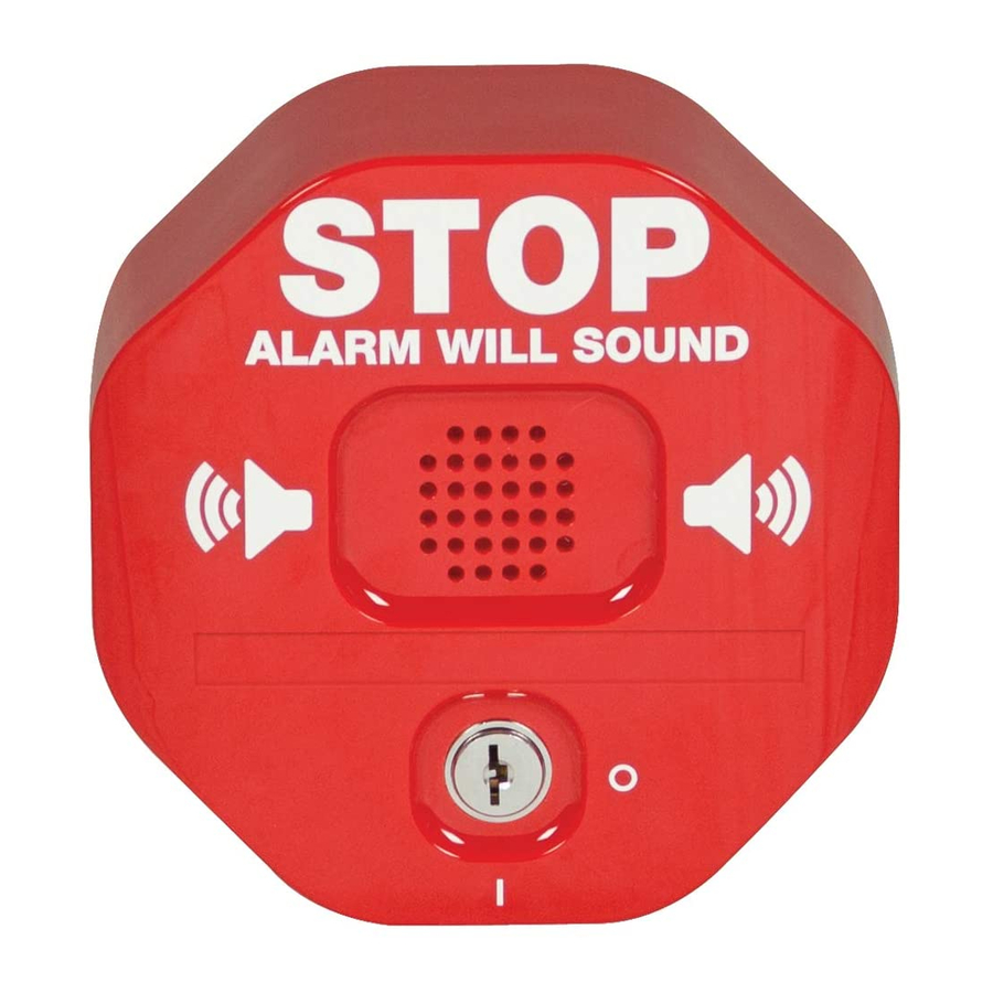
STI-6400 Exit Stopper
INSTRUCTION MANUAL
Features:
• Helps prevent both unauthorized exits and entries
through emergency exit doors.
• Easy to install.
• Less expensive than heavy horizontal bar type units and
practical for all emergency doors.
• May be mounted on top, right, left or next to almost any
door.
• User can select onsite whether to use an alarm or
annunciator.
• Contact STI for custom applications.
Safety Technology International, Inc.
"We rotect The Things That rotect You. "
®
Advertisement
Table of Contents

Subscribe to Our Youtube Channel
Summary of Contents for STI STI-6400
- Page 1 • May be mounted on top, right, left or next to almost any door. • User can select onsite whether to use an alarm or annunciator. • Contact STI for custom applications. Safety Technology International, Inc. “We rotect The Things That rotect You. ”...
- Page 2 Results from this test may prove it beneficial to purchase additional exit stopper units. When purchasing a remote unit (STI-6403) you will need to periodically test the connections to make sure audibles function at a sound level to alert staff. Maximum of three STI-6403 may be used in parallel.
- Page 3 50mA at 95 dB/ 200 mA at 105 dB *Power source for the STI-6403 Remote Horn uses a separate power source from the STI-6400 alarm. The Remote Horn contains an internal 9 volt battery. Horn operates when the Form C...
- Page 4 IRCUIT OARD (ON) ALARM VOLUME SWITCH TERMINAL BLOCK (OFF) TRIP DELAY SWITCH (OFF) ALARM DURATION SWITCH (OFF) (FACTORY DEFAULT SETTINGS) (ON) ARMING SWITCH FIGURE 1 NC COM NO GD KEYSW TERMINAL BLOCK WIRING CONNECTIONS WITCH ETTINGS FEATURE Volume - High (105 dB) at 1 ft. Volume - Low (95 dB) at 1 ft.
- Page 5 In “OFF” position delay arming will allow 15 seconds for you to exit through the door without sending alarm signal. NSTALLATION NSTRUCTIONS Note: STI recommends setting up unit and testing settings prior to mounting. 1. Make sure key switch is in the OFF position. 2. Remove tamper screw on side of unit and remove housing cover.
- Page 6 3/8 in. [9.5mm] ON METAL DOOR AND FRAME DOOR STOP MAGNET 6400 UNIT DOOR SWING FIGURE 5 *Note: When mounting reed switch on door and the main unit on wall, wire service loop must be used. TYPICAL DOUBLE DOOR INSTALLATION STI-6402 FIGURE 6...
- Page 7 OUBLE OOR WITH EMOTE NSTALL OTES The STI-6404 is a combination unit for double doors with a remote horn. Reference the installation instructions for the main unit, the STI-6402 and the STI-6403 for complete installation. STI-6405 E TOPPER WITH OMENTARY ESET The STI-6405 uses a momentary switch.


Need help?
Do you have a question about the STI-6400 and is the answer not in the manual?
Questions and answers