Table of Contents
Advertisement
Advertisement
Table of Contents

Related Manuals for iCanTek iCanView 110


Summary of Contents for iCanTek iCanView 110
- Page 1 User’s Guide iCanView110/110W Rev1.4(Jan. 2005)
- Page 2 iCanView110/110W User’s Guide Directions iCanView110 is designed for indoor use only. When using iCanView110 outdoors or in n environment that exceeds the limited range, you must separately use a water-resistant case. Be careful not to cause any physical damage by dropping or throwing the iCanView110 A/V Server. Especially keep the A/V server out of reach from children.
- Page 3 iCanView110/110W User’s Guide Caution Any changes or modifications in construction of this device which are not expressly approved by the party responsible for compliance could void the user’s authority to operate the equipment. This appliance and its antenna must not be co-located or operating in conjunction with any other antenna or transmitter.
-
Page 4: Table Of Contents
iCanView110/110W User’s Guide Table of Contents 1. Introduction............................5 1.1. Overview.......................... 5 1.2. Features of iCanView110....................5 1.3. Applications of iCanView110 ..................5 2. Product Description ..........................7 2.1. Contents .......................... 7 2.2. Preview ..........................7 2.3. Physical description......................8 2.5 Quick Installation Guide.................... -
Page 5: Introduction
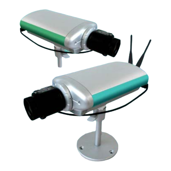
iCanView110/110W User’s Guide 1. Introduction 1.1. Overview The iCanView110 is a state-of-the-art network camera (and simultaneously a 1-channel A/V server) which transmits both video and audio data in real time with high-resolution at high frame rate. This is possible through MPEG4 CODEC technology, which provides data transmission at high compression rates with high data resolution via networks. - Page 6 iCanView110/110W User’s Guide Real time Internet broadcasting (resort areas, events, etc.) Remote monitoring (hospitals, kindergartens, traffic, public areas, etc.) Teleconference (Bi-directional audio conference) Remote Learning Weather and environmental observation Rev.1.4 (Jan. 2005) 6 of 56...
-
Page 7: Product Description
iCanView110/110W User’s Guide 2. Product Description 2.1. Contents Open the package and check if you have the followings: Components Description Remarks iCanView110(W) iCanView110 Network Camera/Server Input : 100~250V 50-60Hz Power adapter Output : +12V, 1.0A AC power cable AC 250V, 10A~16A For direct connection LAN cable 2m LAN cable –... -
Page 8: Physical Description
iCanView110/110W User’s Guide 2.3. Physical description 2.3.1. Front View Fixed Focus Lenz (F1.3, 6mm Fixed Focus) Microphone Status Indicator LED CS Lens Mount ring Figure 2-1. Front view of iCanView110 Lens Assembly : It is a fixed focus lens with CS type mounting fixture. It can be replaced with other types with C/CS mounted fixed focus lens or DC IRIS lens. - Page 9 iCanView110/110W User’s Guide Microphone : Picks-up sound from the environment for transmission over the network.. Mount Ring : Used for attaching lens unit to iCanView110. 2.3.2. Rear panel Figure 2-2. Rear Panel of iCanView110/110W MIC /LINE IN : It is used to connect external audio source or microphone to iCanView110. If external audio is connected, embedded microphone will be disabled.
- Page 10 iCanView110/110W User’s Guide RS-232C (3 pins) : Used only by developers for development and production. Not for use by end users. DC12V, 1A: Power input of iCanView110. 12V/1A DC-IRIS : Plug in the cable attached on standard DC-Iris lens. RS-485 and ALARM IN/OUT : Is is used for connecting P/T/Z and alarm devices to iCanView110.
- Page 11 iCanView110/110W User’s Guide Rev.1.4 (Jan. 2005) 11 of 56...
-
Page 12: Quick Installation Guide
Brief information for rapid installation is provided in this section. For more detailed information you are recommended to refer to pertinent documentations provided with the product or refer to iCanTek’s home page (http://www.icantek.com) 1. Connect iCanView110 to your PC or network by using one of the following method i. - Page 13 iCanView110/110W User’s Guide 5. Connect to iCanView110 in Administrator Mode for initial parameter set-up. All parameters are set to factory default state when iCanView110 is delivered to you. You are asked to configure the system for your environment in administration mode. Detailed information of using administration mode can be found in [5.
- Page 14 iCanView110/110W User’s Guide connector CCTV camera, DVD, TV etc., (NTSC/PAL/SECAM) LINE- Connect microphone or output from Audio in In/MIC audio devices. When in bi-directional audio mode, Audio out for Audio signal from remote site Line Out speaker available from this connector. Use speaker with amplifier.
-
Page 15: Connecting The Icanview110
iCanView110/110W User’s Guide 3. Connecting the iCanView110 iCanView110 supports LAN, xDSL, and Cable modem. It also support shared IP network where single IP is shared by many devices using IP sharing device. Refer to [IP-Installer User’s Guide] for details of setting the IP address for the iCanView110 by using the “IP-Installer”. 3.1. -
Page 16: Connecting To Xdsl Modem
iCanView110/110W User’s Guide 3.2. Connecting to xDSL Modem 1. Apply power and connect the PC and iCanView110 using crossover LAN cable provided with the system. 2. Setup network parameters by running “IP-Installer.” Figure 3-2. Direct connection using crossover LAN cable Figure 3-3. -
Page 17: Connecting To Cable Modem
iCanView110/110W User’s Guide 3. Remove the crossover LAN cable and connect the iCanView110 to the network using regular LAN cable. Check if you can receive video data when connecting to iCanView110 using the viewer program. When fixed IP address is assigned to the xDSL, follow the same way as assigning IP address for the case of LAN using IP-installer. - Page 18 iCanView110/110W User’s Guide Figure 3-4. Direct connection using crossover LAN 3. Remove the crossover cable and connect the iCanView110 to the network using regular LAN cable as shown in Figure 3-5. Check if you can receive video data when connecting to iCanView110 using the viewer program.
- Page 19 iCanView110/110W User’s Guide When fixed IP address is assigned to the Cable Modem, follow the same way as assigning IP address for the case of LAN using IP-installer. To enable the notification of the changed IP address to the user over e-mail when the IP address is changed in floating IP environment, you have to assign the e-mail address when user name and password input...
-
Page 20: Ip-Installer
PC program developed to assign an IP address and setup network parameters to digital video security network products such as Network Camera and A/V Server. IP-Installer is provided in a CD supplied with iCanView110 or it can be downloaded from “www.icantek.com”. Detailed information of Installing and running IP-installer can be found in [IP-installer user’s guide]... -
Page 21: Configuring The A/V Server In Administrative Mode
iCanView110/110W User’s Guide 5. Configuring the A/V Server in Administrative Mode 5.1. Log On There are 2 ways of connecting to iCanView110 administrative mode. One is through standard internet browser(Internet Explorer) and the other is through “i-NVR” program. 1. Using Internet Explorer You can log on to the server by clicking admin mode button or from your internet browser. - Page 22 iCanView110/110W User’s Guide Figure 5-2. Log On Screen Factory default User Name and Password are set as ‘root’ and ‘dw2001’, respectively. Click on “OK” button to enter into the Basic Setup page of Admin Mode. If you have changed the username and password of the Administrator, you must log on with the changed username and password.
-
Page 23: Basic Setup
iCanView110/110W User’s Guide 5.2. Basic Setup Setup the basic parameters of the iCanView110. Figure 5-3. Basic Setup Language Selection: You can select a language in the admin page. - Supported languages : English, Korean, Japanese, Chinese, Spanish System Name It is the name of the iCanView110. It is same as the one set-up by IP-installer. You can reassign the system name in admin mode. - Page 24 iCanView110/110W User’s Guide - Video Size : Select a video size for transmission. Allowed video size is different for each video standard. - NTSC(30 frames/sec Max.) : 176x144 / 320x240 / 640x240 / 640x480. - PAL/SECAM (25 frames/sec Max.) : 176x144 / 352x288 / 704x288 / 704x576 Max upload rate Assign maximum bandwidth of the uplink for the network connected to iCanView110.
-
Page 25: Network Configuration
iCanView110/110W User’s Guide 5.3. Network Configuration Setup the network parameters appropriately in accordance with your network environment. Many of the parameters in this page is same as those used setup by “IP-Installer”. Figure 5-4. Network Configuration IP Assign Type : The network types supported by the iCanView110 are LAN(fixed IP), PPPoE, and DHCP(automatic IP allocation) Rev.1.4 (Jan. - Page 26 iCanView110/110W User’s Guide - When the network environment is fixed IP, select ‘LAN’ in the network type, and put the IP address, Subnet Mask, Gateway, DNS1 and DNS2 assigned by the network administrator or ISP. DNS2 is used when DNS1 does not work. When the network environment is PPPoE and IP address is assigned automatically, select ‘PPPoE’...
- Page 27 iCanView110/110W User’s Guide the IP address changes. It is sent to the E-mail address set by “Recv E-Mail Address”. FTP Server Setup : Setup IP address, Username, Password and Directory of FTP server to send data in case of alarm. Default FTP port number is 21. Management Server : You can register the network camera to the Management Server for various support including name service for your network camera.
-
Page 28: Wireless Configuration
iCanView110/110W User’s Guide 5.4. Wireless Configuration For the case of a network camera having built in wireless LAN it is needed to set up wireless LAN configuration parameters. Click “Wireless Configuration”. Figure 5-5 Wireless Configuration Wireless LAN Setup Set up parameters for wireless LAN. - Use Wireless LAN : Select “Enable”... - Page 29 iCanView110/110W User’s Guide - BSSID : Indicates the ID of the connected Access Point. In general the MAC address of the Access Point is shown. - Current Channel : Indicates the channel number of present connection. - Signal Strength : Indicates the strength of the received signal. - Link Quality : Indicates the quality of the Link level.
-
Page 30: Ccd Adjustment
iCanView110/110W User’s Guide 5.5. CCD Adjustment You can optimize the quality of input video by adjusting the parameter of CCD. To enter into this mode, click “CCD Adjustment” in administrative page. You will find a screen shown in Figure 5-6. Click “SAVE”... - Page 31 iCanView110/110W User’s Guide DC IRIS lens is a kind of auto IRIS lens. Opening of IRIS can be adjusted by applying DC voltage. The opening of IRIS is optimally DC IRIS Lens adjusted by detecting the signal level from CCD. This type is selected when CS Type DC IRIS lens is mounted on your iCanView110.
- Page 32 iCanView110/110W User’s Guide sub menus are activated when this mode is selected. Check the box at the left of each sub menu and click “SAVE” to apply the sub menu. □ Shutter Speed Electronic shutter speed can be selected between 1/60 sec and 1/10000 sec for NTSC camera.
-
Page 33: User Admin & Time Setup
iCanView110/110W User’s Guide 5.6. User Admin & Time Setup You can change the ID and password of users and also assign different attributes for each user. You can change the ID and password of users and also assign different attributes for each user. Figure 5-7. - Page 34 iCanView110/110W User’s Guide Add User Username : Enter the user ID you want to add. Up to 100 users are supported by iCanView110. Password: Enter the user password. . Attribute : You can set different system resource access capabilities for each of the user. Attributes are Audio, Bi-directional Audio and Pan/Tilt.
- Page 35 iCanView110/110W User’s Guide - Time Settings : You can set the time manually or you can synchronize the time to the PC. Options Description “Synchronize With Computer Time” Synchronize the time with the PC time. “Set Manually” You can manually set the time. Rev.1.4 (Jan.
-
Page 36: Sensor & Capture Setup
iCanView110/110W User’s Guide 5.7. Sensor & Capture Setup This is the setup page for sensors and video capture conditions, which will be sent to user by FTP or E-mail. Figure 5-9. Sensor & Capture Setup Sensor Setup : A sensor can be connected to iCanView110. - Type Selection : Select sensor type. - Page 37 iCanView110/110W User’s Guide - FTP is sent to the FTP Server. Refer to [Section 5.3.] E-mail is sent to the Recv E-mail address. Refer to [Section 5.3.] If the FTP server is not properly assigned in “Network Configuration” mode, iCanView110 ignores the video transmission by FTP Captured video...
-
Page 38: Alarm Device Setup
iCanView110/110W User’s Guide 5.8. Alarm Device Setup Test alarm output and describe the condition of alarm. Figure 5-10. Alarm Output Setup Alarm Device Test : Test alarm devices. Press On/Off for testing. Alarm Device Active Condition : Setup the condition of activating alarm Device. Select sensor or motion detection as the condition. -
Page 39: Motion Region Setup
iCanView110/110W User’s Guide 5.9. Motion Region Setup Set the motion detection regions. Up to 3 regions can be defined. Figure 5-11. Motion Region Setup Channel Selection : Choose the channel you want to enable motion detection. Channel Sensitivity : Set the sensitivity in motion detection for each channel. - 1 is the least sensitive number, and 66 is the most sensitive number. - Page 40 iCanView110/110W User’s Guide . You can set the region by pressing the “START” button, and click one corner of region in the left viewing. It will show the coordinate value automatically. Next you press the “END” button, and click the other diagonal corner. Regions are shown in three different transparent colors: red(region 1), green(region 2), blue(region3) “RESET”...
-
Page 41: Ptz Setup
iCanView110/110W User’s Guide 5.10. PTZ Setup Setup and test the PTZ devices. Figure 5-12. PTZ Setup Channel Selection : Choose the channel having PTZ device. PTZ Model Selection : Choose the PTZ model for each channel. Different PTZ model can be applied for each channel. - Delete Button : Press this button to delete the setup of PTZ. - Page 42 iCanView110/110W User’s Guide “Left”/”Right”/”UP”/”DOWN” , “AUTO FOCUS”/”ZIN”/”ZOUT” PTZ Operation Check : You can check the various operation of the PTZ devices. “Left”/”Right”/”UP”/”DOWN” , “AUTO FOCUS”/”ZIN”/”ZOUT” PTZ Position Setup : You can set up the PTZ limitation & preset positions if the PTZ device supports it.
-
Page 43: Encryption Set Up
iCanView110/110W User’s Guide 5.11. Encryption Set up Figure 5-13. Encryption Setup For additional security to the video and audio data transmitted from the network camera, you can set key codes and use them for encrypting the data from the network camera. You can selectively activate encryption for the video and audio data. - Page 44 iCanView110/110W User’s Guide - Downloading Key value to your PC : The key values can be downloaded and stored as a file to your PC for reference when you make connection. When encryption is enabled, the PC client program will ask for particular key value out of the 20 available key values. - Uploading key value to the video server : The key value stored on your PC can be uploaded to your network camera.
-
Page 45: Upgrade & Reset
You can upgrade the iCanView110 via the network. Figure 5-14. Upgrade & Reset For each of the upgrade of the system component, upgrade code should be downloaded from iCanTek’s home page before the system upgrade is performed. (Refer to [6.4. How To Upgrade Your iCanView110 System]... - Page 46 User’s Guide Bootloader needed for the upgrade can be downloaded from iCanTek’s home page. Refer to [6.4. How To Upgrade Your iCanView110 System]. - Add PTZ File : Add a new PTZ driver software via the network. PTZ driver can be downloaded from iCanTek’s home page.
-
Page 47: Status Report
iCanView110/110W User’s Guide 5.13. Status Report It shows you system records since the system started. Figure 5-15. Status Report You can check the problems as well as the versions and event status of the whole system and each module. Rev.1.4 (Jan. 2005) 47 of 56... -
Page 48: Tips For Using Icanview110
iCanView110/110W User’s Guide 6. Tips for Using iCanView110 6.1. ALARM-IN and ALARM-OUT ALARM connectors are used to connect various sensing and alerting devices. Examples of sensing devices are infrared sensors, motion sensors, heat/smoke sensors, magnetic sensor, etc. ALARM- OUT t is used for connecting alerting device such as loud speaker, flashing light, etc. Figure 6-1. - Page 49 iCanView110/110W User’s Guide Figure 6-2. SENSOR input of iCanView110 2. ALARM-OUT A Relay output is provided for connecting alarm devices or for remote on/off devices such as light control. Relay circuits are normal open and circuits are closed upon alarm output or remote on.
- Page 50 iCanView110/110W User’s Guide 3. Connection of Sensor, Alarm Device 3.1 Connection of Sensor Photo Coupler NO/NCType Open CollectorType Sensor1+ Sensor Sensor Device Device Sensor1- +12V Sensor Sensor Power Power Supply Supply 3.2 Connection of Relay Relay Switch Power Supply Alarm 1V~30VDC/AC,1A Device Power...
-
Page 51: Trouble Shooting
iCanView110/110W User’s Guide 6.2. Trouble Shooting 1. After iCanView110 is successfully installed. • iCanView110 in viewing mode, neither channel name nor video is display and eventually timeout message is shown up. Check the power and network connection of iCanView110. To check if the network is properly operating, open the browser and try to connect to any server. - Page 52 iCanView110/110W User’s Guide 2. After Successfully Connecting to the iCanView110 • Video movement is slow. In Basic Setup of Admin Mode, lower the “Quality”. High quality means more data. You can also set the “Max. Bandwidth” to higher value. But this value must be lower than the maximum upload speed of your network.
-
Page 53: Web Viewer
iCanView110/110W User’s Guide 6.3. Web Viewer iCanView110 is designed to be connected through internet explorer, too. For connection to iCanView110 using internet explorer type in IP address or host address in the address input field of the internet explorer. Figure 6-4. Web Viewer of iCanView110 Control Panel of Web Viewer Enable bidirectional... - Page 54 iCanView110/110W User’s Guide Connect to iCanView110. Stop the connection. Contrast, Brightness, Volume adjustment.. Check the box to mute the audio. Adjust the size of the screen. Normal (x1), Twice (x2), Half (1/2), Full Screen (full) On/off the relay by pressing the button Shows the status of the sensor.
-
Page 55: How To Upgrade Your Icanview110 System
2. Manual Upgrade 1) Save the upgrade system software to your PC. Upgrade software can be downloaded from iCanTek’s home page or provided in CD. 서식 있음: 글머리 기호 및 2) Log on to administrative mode and select “Update & Reset” menu. - Page 56 8) After rebooting, log on to the server in administrative mode again and click the “Status Report”. 서식 있음: 글머리 기호 및 9) Check the version number and release date of the iCanView110. 번호 매기기 You can download iCanView110 system software from iCantek’s homepage. http://www.icantek.com Rev.1.4 (Jan. 2005) 56 of 56...
Need help?
Do you have a question about the iCanView 110 and is the answer not in the manual?
Questions and answers