Table of Contents
Advertisement
Available languages
Available languages
Quick Links
smart
EN
Video & AUDIO DOOR PHONES
Technical Manual
Apartment Buildings
smart
smart
smart +
classic
mini
+
extra
RO
INTERFOANE VIDEO & AUDIO
Carte tehnică
Blocuri de locuințe
smart +
smart
smart +
video
extra
ok
audio
Advertisement
Table of Contents

Subscribe to Our Youtube Channel
Related Manuals for Electra SMART+


Summary of Contents for Electra SMART+
- Page 1 smart smart extra VIDEO & AUDIO DOOR PHONES INTERFOANE VIDEO & AUDIO Technical Manual Carte tehnică Apartment Buildings Blocuri de locuințe video smart smart + smart + extra audio classic mini smart smart +...
- Page 2 CONTENUTO CONTENTS CONTENTS CUPRINS FEATURES & SYSTEM COMPONENTS pg. 1...12 FUNCȚIUNI & COMPONENȚA INSTALAȚIEI pg. 1...12 BLOCK DIAGRAMS SCHEME BLOC Video Systems pg. 13...14 Instalații video pg. 13...14 Audio Systems pg. 15 Instalații audio pg. 15 Mixed video-audio systems pg. 16...17 Instalații mixte video-audio pg.
- Page 3 Maximum attention for correct installation/ Risk of electric shock! wire connection. Authorized personnel required! Atenție maximă pentru corectitudinea instalării/ Pericol de șoc electric! conectării firelor. Intervenția se face doar de către personal autorizat! FUNCȚIUNI FEATURES 1. Up to 255 apartments Până...
- Page 4 Call Apel Video + Answer Video + Răspuns 5. Hands-free talk Convorbire hands-free 6. Access granting Acordare acces...
- Page 5 Video & Audio monitoring Monitorizare video & audio Volume levels Niveluri de volum MUTE 9. Setting the ringing duration Setarea duratei apelului 5 sec 5 sec 5 sec 1 min 10. Multiple ringtones Mai multe melodii de apel...
- Page 6 11. Access with RFID tag Acces cu tag RFID Funcțiuni opționale Optional features 12. Additional video cameras Camere video adiționale 13. Auxiliary command Comandă auxiliară 14. Additional terminals Terminale adiționale video 7” video 3.5” audio...
- Page 7 15. Additional panels Panouri adiționale 16. Pictures memory Memorare imagini 17. Intercommunication Intercomunicare...
- Page 8 COMPONENȚA INSTALAȚIEI SYSTEM COMPONENTS VPM.BFR02 VPM.BSR02 Case AL profile + Chemically toughened glass - 8 mm Carcasă Profil AL + Sticlă securizată chimic – 8mm smart Outdoor panel Panou exterior smart CMOS, IR-CUT 414 x 144 x 53 mm 380 x 110 x 33 mm 2,3 kg 2 kg 1/3", 573(H) x 597(V), 800 TVL...
- Page 9 VTM.7S402 Case ABS + Chemically toughened glass - 3 mm Carcasă ABS + Sticlă securizată chimic – 3 mm smart + Video terminal 162 x 227 x 20 mm Terminal video smart + 0,8 kg 7“ LCD, TFT 0 C … + 45 C LCD display 800 x 3 (RGB) x 480 Display LCD...
- Page 10 ATM.0S302 smart Audio terminal Case ABS + Chemically toughened glass - 3 mm 170 x 96 x 22 mm Carcasă ABS + Sticlă securizată chimic – 3 mm Terminal audio smart 0,3 kg 0 C … + 45 C 12 … 14 Vd.c. ATM.0S402 smart + Audio terminal Case...
- Page 11 SCU.VDR02 Fireproof ABS Case Connections ABS ignifugat Carcasă Conexiuni Video central unit 130 x 141 x 73 mm Unitate centrală video 0,4 kg 0 C … + 45 C DIN rail mounting TH 35 x 15 / 35 x 7,5 Montaj pe șină...
- Page 12 VCB.10DR02 Connections Case Carcasă Conexiuni Video connection box 130 x 141 x 73 mm Doză derivație video 0,4 kg TH 35 x 15 / 35 x 7,5 0 C … + 45 C 1 input - 10 outputs DIN rail mounting DIN 46277-3, En50022, 1 intrare - 10 ieșiri Montaj pe șină...
- Page 13 Programator adrese terminale Programmer for terminals addresses VTM.7S402 VTE.7S902 7“ LCD, TFT Video terminal in parallel 800 x 3 (RGB) x 480 Terminal video în paralel / / / - 60/ 60/ 40 / 60 227 x 162 x 20 mm VTM.3S302 VTM.3S402 3,5”...
- Page 14 For additional video cameras Passive video balun Pentru camere adiționale Balun video Vcam 1 video camera connected directly in SCU.VDR02 1 cameră video conectată direct în SCU.VDR02 Vcam Up to 4 video cameras (12 Vd.c. power supply for each) Până la 4 camere video (fiecare cu sursă de alimentare de 12 Vc.c.) Additional power supply 12...14Vd.c...
- Page 15 BLOCK DIAGRAMS SCHEME BLOC 3.1.1 VIDEO VTM(E) VCB.4DR02.ELW VCB.4DR UTP cat5e VTM(E) (AWG 24) VTM(E) VCB.4DR02.ELW VCB.4DR UTP cat5e VTM(E) (AWG 24) 230 Va.c., 50 Hz 3 x 0.75 mm 2 x 6Aa.c. UTP cat5e (AWG 24) 12V 7Ah Vcam 2 x 0.75 mm UTP cat5e PROG...
- Page 16 3.1.2 VIDEO VTM(E) VTM(E) UTP cat5e UTP cat5e (AWG 24) (AWG 24) VCB.10DR VTM(E) VTM(E) VTM(E) 230 Va.c., 50 Hz 3 x 0.75 mm 2 x 6Aa.c. UTP cat5e (AWG 24) 12V 7Ah Vcam 2 x 0.75 mm UTP cat5e PROG STROMVERSORGUNGSEINHEIT (SCU.VDR02.BLW)
- Page 17 3.1.3 AUDIO VSB.4DN02.BLW VCB.3DN02.BLW IN: 4 OUT: 1 OUT: 3 : 12-14 V : 12-14 V IN-OUT: 1 ACB.4DR VSB.4DN02.BLW VCB.3DN02.BLW IN: 4 OUT: 1 OUT: 3 : 12-14 V : 12-14 V IN-OUT: 1 ACB.4DR UTP cat5e (AWG 24) 230 Va.c., 50 Hz 3 x 0.75 mm 2 x 6Aa.c.
- Page 18 3.1.4 AUDIO - VIDEO VCB.4DR02.ELW VCB.4DR UTP cat5e VTM(E) (AWG 24) VCB.4DR02.ELW VCB.4DR UTP cat5e (AWG 24) VTM(E) 230 Va.c., 50 Hz 3 x 0.75 mm 2 x 6Aa.c. UTP cat5e (AWG 24) 12V 7Ah Vcam 2 x 0.75 mm UTP cat5e PROG STROMVERSORGUNGSEINHEIT...
- Page 19 3.2. UTP cat5e UTP cat5e (AWG 24) (AWG 24) VTM(E) VTM(E)2 VTM2 UTP cat5e UTP cat5e (AWG 24) (AWG 24) Additional terminals VTM2 VTM(E)2 Terminale adiționale UTP cat5e UTP cat5e (AWG 24) (AWG 24) ATM2 ATM3 ATM4 VTM(E) UTP cat5e (AWG 24) ATM2 ATM3...
-
Page 20: Installation Steps
SAFETY INSTRUCTIONS during installation 1. ATTENTION! The installation, the maintenance and the connection to the 230V/50Hz network of the central unit (SCU) will be carried out only by authorized personnel! 2. ATTENTION! It is MANDATORY to use a 3 x 0,75 mm cable and 2 automatic fuses (6A) for power supplying the central unit (SCU) from the 230V/50Hz network. - Page 21 INSTRUCȚIUNI DE SIGURANȚĂ în timpul instalării 1. ATENȚIE! Instalarea, întreținerea și conectarea unității centrale (SCU) la rețeaua de 230V/50Hz se va face numai de către personal autorizat! 2. ATENȚIE! Este obligatorie utilizarea unui cablu de 3 x 0,75 și a 2 siguranțe automate (6A) pentru alimentarea unității centrale (SCU) de la rețeaua de 230V/50Hz.
- Page 22 INSTALLATION INSTALARE 5.1. UTP cat 5 (AWG24) UTP cat 5 (AWG24) VTM(E), UTP cat 5e (AWG24) UTP cat 5 (AWG24) + 3 x 0.75 + 3 x 0.75 + 3 x 0.75 + DVA.1PS02 DVA.1PS02 + SAC Audio 200 m 400 m 400 m 600 m...
- Page 23 5.2. VPM / APM 5.2.1 Installation of the outdoor panel Instalarea panoului exterior 5.2.2 Torx 1 Flush version Versiunea îngropată Torx 2 5 cm ≈20 cm 5.2.3 Surface version Versiunea pe suprafață Torx 2 ≈20 cm Antitheft protection. Screw the Torx 2 completely! Protecție antifurt.
- Page 24 5.2.6 audio Electrical connections Conexiuni electrice UTP cat5e (AWG 24) 5.3. VCB / ACB 5.3.1 VCB.4DN02.ELW VCB.3DN02.BLW Installation of the connection box OUT: 3 : 12-14 V IN-OUT: 1 Instalarea dozei de derivație 5.3.2 Electrical connections with RJ45 connector Conexiuni electrice cu conector RJ45 VTM(E) 1 VTM(E) 2 UTP cat5e...
- Page 25 VTM(E) 1 VTM(E) 2 VTM(E) 3 VTM(E) 4 VTM(E) 5 VCB.10DR02.ELW (Optional) UTP cat5e (AWG 24) SCU/VCB VTM(E) 6 VTM(E) 7 VTM(E) 8 VTM(E) 9 VTM(E) 10 ATM 1 ATM 2 UTP cat5e (AWG 24) ACB.4DR02.ELW UTP cat5e (Optional) (AWG 24) UTP cat5e (AWG 24) UTP cat5e...
- Page 26 5.3.3 Conexiuni electrice cu conectori cu șurub Electrical connections with screw connectors UTP cat5e UTP cat5e VTM(E) 1 (AWG 24) (AWG 24) VCB.3DN02.ELW (Optional) UTP cat5e UTP cat5e UTP cat5e VTM(E) 2 (AWG 24) (AWG 24) (AWG 24) UTP cat5e UTP cat5e ATM4 ATM3...
- Page 27 5.4. VTM / VTE / ATM 5.4.1. VTM.7S402 / VTE.7S902 (7”) 5.4.1.1 Surface Installation of the video terminal Pe suprafață Instalarea terminalului video ≈20 cm UTP cat5e (AWG 24) 5.4.1.2 Electrical connections with RJ45 connector Conexiuni electrice cu conector RJ45 UTP cat5e (AWG 24) 5.4.1.3 UTP cat5e...
- Page 28 5.4.2.2 Electrical connections with RJ45 connector Conexiuni electrice cu conector RJ45 UTP cat5e (AWG 24) 5.4.2.3 UTP cat5e Electrical connections with screw connectors (AWG 24) Conexiuni electrice cu conectori cu șurub Türklingel Doorbell VTM - 3.5” 5.4.3. ATM.0S302 / ATM.0S402 (audio) 5.4.3.1 Surface Installation of the audio terminal...
- Page 29 5.4.3.3 UTP cat5e (AWG 24) Electrical connections with screw connectors Türklingel Conexiuni electrice cu conectori Doorbell cu șurub 5.4.4. ATm.0S302 (audio mini) 5.4.4.1 Surface ≈20 cm Installation of the audio terminal UTP cat5e Pe suprafață (AWG 24) Instalarea terminalului audio 5.4.4.2 Electrical connections with RJ45 connector Conexiuni electrice cu...
- Page 30 5.4.5.3 UTP cat5e Electrical connections with screw connectors (AWG 24) Conexiuni electrice cu conectori cu șurub 5.4.6 UTP cat5e Terminals in parallel (AWG 24) Terminale în paralel UTP cat5e (AWG 24) VIDEO VIDEO Türklingel Doorbell VTM(E) - 7”/3.5” VTM(E) - 7”/3.5” 5.4.7 UTP cat5e Terminals in parallel...
- Page 31 5.5. SCU 5.5.1. SCU.VDR02 (video) 5.5.1.1 Installation of the central unit PROG Touch Line - SCU.VDR02.ELW Lebensgefahr! Gerät nicht öffnen! Danger! Do not unfasten the lid! Instalarea unității centrale : 230V, 50Hz, 0.4A Danger! Ne pas démonter le couvercle! Pericolo! Non togliete il coperchio! S1: 14V, 2A Peligro! No desmontar la cubierta! TIME (S)
- Page 32 5.5.1.3 Conexiuni electrice cu conectori cu șurub Electrical connections with screw connectors Vcam UTP cat5e 230 Va.c. 2 x 6Aa.c. (AWG 24) 50Hz Vcam 3 x 0,75 mm² Vcam 1.6A Vcam SCU.VDR02 +14V 0.75 mm² 2 x 0.75 mm² UTP cat5e 0.75 mm²...
- Page 33 5.5.2. SCU.ADN02 (audio) 5.5.2.1 VSB.4DN02.BLW STROMVERSORGUNGSEINHEIT (SCU.ADN02.BLW) PROG EINGANG : 230V Wechselspannung 50Hz, 0.4A IN: 4 OUT: 1 : 12-14 V Installation of the central unit AUSGANG 1: 14V, 2A Gleichspannung (S1) ACHTUNG! Lebensgefahr, Gerät nicht öffnen! SCHLOSS- ÖFFNUNGS- GEFAHR EINES ZEIT Instalarea unității centrale STROMSCHLAGS!
- Page 34 5.6. Checking the voltages (SCU connected to 230 Va.c.) Verificarea tensiunilor de alimentare (SCU connected to 230 Va.c.) 5.6.1 SCU.VDR02 Checking the voltages Verificarea tensiunilor de 13,5 14,3Vd.c. 13,5 14,3Vd.c. alimentare +14V 13,5 14,3Vd.c. 3.0 4.8Vd.c. 5.6.2 Checking the voltages Verificarea tensiunilor de alimentare 3.0 4.8Vd.c.
- Page 35 5.6.4 +14V +14V SCU.ADN02 Checking the voltages 13,5 14,3Vd.c. 3.0 4.8Vd.c. Verificarea tensiunilor de alimentare +14V 13,5 14,3Vd.c. 5.6.5 Checking the voltages Verificarea tensiunilor de alimentare 3.0 4.8Vd.c. 14.3Vd.c. 5.6.6 ATM/ACB ATM/ACB ATM/ACB Checking the voltages Verificarea tensiunilor de alimentare 3.0 4.8Vd.c.
- Page 36 USE OF THE DOOR PHONE 6.1. Safety instructions during use DO NOT HIT the products with hard objects. è PROTECT THE PRODUCTS against lime and dust during renovation. è 6.2. Significance of the acoustic signals / use of the key s BEEP Short confirmation beep with a high tone.
- Page 37 Significance of LEDs signaling BUTTON PROG PROG The system is not connected to the 230 Va.c./ 50 Hz network. The system is OK, connected to the 230 Va.c./ GREEN GREEN 50 Hz network. Long press Programming mode GREEN GREEN When a battery is connected to SCU, there are the following additional signals only for S3 LED: The system is not connected to the 230 Va.c./ 50 Hz network.
- Page 38 6.4. Use of the outdoor panel (VPM/APM) 6.4.1. Programming The main steps are the following: 1. Programming the installer' s PIN code in the outdoor panel. 2. Programming the codes of the access tags in the outdoor panel. 3. Programming the addresses of the outdoor panels in the case of parallel connection - max. 4. 4.
- Page 39 The programming In case that additional outdoor panels are added to the system, the following programming procedure must be followed for each additional panel. Supply control unit PROG Long press of PROG. The red LED turns on. Step 1 Long press the key.
- Page 40 Press key 2 for adding the codes. A 1x[ ] confirmation is issued. BEEEEP The following message is displayed: Insert tag X / 46080 Adding Touch the tags, one by one, to the icon until all the tags necessary for the access of the inhabitants in the building are access memorised.
- Page 41 IBM Pentium II computer, 400 MHz, with USB serial interface, operating system: Ÿ Windows 98, Windows XP, Windows Vista, Windows 7 serial communication interface: INT.COM1 (supplied by the producer) Ÿ software: InterProg, licensed by ELECTRA is available on the webpage: Ÿ http://www.electra.ro, with the user password.
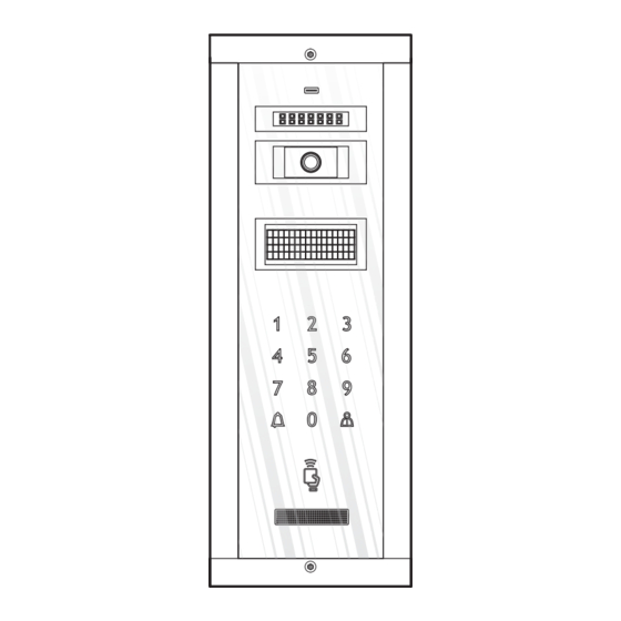
- Page 42 Connecting the microUSB to the apartment building panel, using the ADP.004.PAS adapter for the supply with power of the panel. 6.4. 2. Functioning IR LEDs (night lighting) Adjustable video camera Electronic display W e l c o e ! W e l c o e ! D i a l u m b e r D i a l...
- Page 43 The keypad and the electronic display are permanently backlit. At the video panels, the red LED is blinking (signaling the possibility of video STAND-BY monitoring). ELECTRONIC The display interacts with the users all the time. In stand-by, it is on and shows as a main message See screen 1.
- Page 44 Connect the front case of the terminal to the PRG.TRM.001 Terminal programming device. The terminals of the programmer will be Step 1 VTM/VTE/ATM connected to the +14V, CD and GND hubs of the terminal Turn the device on, by pressing the ON key. The terminal Step 2 emits a [ BEEP...
- Page 45 6.5. 2. Functioning smart Terminals Call answering + Audio-Video Monitoring (ringtone setting) Access granting (ringing duration setting) Talk volume + mute (ringing volume setting) audio smart video 3.5” smart The factory standard settings are the following: Ringtone Ding-dong (first in the list) Ringing duration 2 calls Ringing volume...
- Page 46 END TALK without Another short touch of access From stand-by Long press of During call, talk or monitoring Short touch of any time. ACCESS GRANTING The access is signaled acoustically also, with a specific confirmation Terminal in stand-by or song and the bidirectional audio communication remains opened during call, talk or monitoring 10 more sec.
- Page 47 smart + Terminals audio smart + video 3.5” smart + video 7” smart + AUX command (auto gate, external lighting etc.) From stand-by Long press of AUX COMMAND During call, talk or monitoring Short touch of any time. The command Terminal in stand-by or during is signaled acoustically also, with a specific confirmation song.
- Page 48 Short touch of Entering in the Menu. Another 4 x short touches of Pictures menu. to navigate through Pictures view or Delete all. VIEW PICTURES / to select the option. DELETE PICTURES In Pictures view, use to navigate. Terminal in stand-by In Delete all, another touch of to delete all the memorized pictures.
- Page 49 When called from the outdoor panel, the terminal rings – 3 x Ding-dong. CALL The LED is blinking red. RINGING VOLUME The terminal has 2 volume levels and they can be adjusted by short successive ADJUSTMENT touches of key. The maximum level is signaled with 2 x [ ]. BEEP Terminal during call Long press of...
- Page 50 When called from the outdoor panel, the terminal rings – 3 x Ding-dong. CALL The LED is blinking red. RINGING VOLUME The terminal has 2 volume levels and they can be adjusted by short successive ADJUSTMENT touches of key. The maximum level is signaled with 2 x [ ]. BEEP Terminal during call Long press of...
- Page 51 S1 red Check the connections between +14V Short circuit between +14V and S2 red or green The system doesn`t work. and GND and/or GNV and +Uv. GND and/or GNV and +Uv. Correct any errors. PROG Only 1 wire connected on +14V The 2nd wire must be connected The system works OK, and GND terminals, instead of 2...
- Page 52 The warranty does not include the access TAGs as they are considered consumable goods. The ELECTRA systems for residential buildings are produced in compliance with the EU standards and bear the CE conformity marking.
- Page 53 UTILIZAREA INTERFONULUI 6.1. INSTRUCȚIUNI DE SIGURANȚĂ în timpul utilizării NU LOVIȚI produsele cu obiecte dure. è PROTEJAȚI PRODUSELE de var și praf în timpul renovării. è 6.2. Semnificația semnalelor acustice/ utilizarea tastelor BEEP Bip scurt de frecvență înaltă pentru confirmare. 2 x [ BEEP Secvență...
- Page 54 Semnificația semnalizării LED-urilor BUTTON PROG PROG Instalația nu este conectată la rețeaua de 230Vc.a./50Hz. Instalația e OK, conectată la rețeaua de VERDE VERDE 230Vc.a./50Hz. Apăsare lungă ROSU VERDE VERDE Mod programare. Când este conectat un acumulator la SCU , se adaugă următoarele semnalizări ale LED-ului S3: Instalația nu este conectată...
- Page 55 6.4. Utilizarea panoului exterior (VPM/APM) 6.4.1. Programare Principalele etape sunt următoarele: 1. Programarea codului PIN al instalatorului. 2. Programarea codurilor tag-urilor de acces. 3. Programarea adreselor panourilor exterioare în cazul conectării în paralel - max. 4. 4. Încărcarea bazei de date(listă locatari, coduri tag-uri, etc.) în panou prin programul InterProg. Panourile devin active după...
- Page 56 Programarea propriu-zisă În cazul în care sunt montate panouri adiționale în instalație, procedura de programare descrisă în continuare trebuie efectuată pentru fiecare panou adițional în parte. PROG Apăsare lungă a butonului PROG. LED-ul roșu se aprinde. Pas 1 Unitate centrală SCU Se apasă...
- Page 57 Se apasă tasta 2 pentru adăugare coduri tag-uri. Se confirmă cu BEEEEP Se afișează: Adaugare Introduceți tag X / 46080 coduri Se ating tag-urile bucată cu bucată de iconița până când tag-uri se memorează toate tag-urile necasare accesului locatarilor din acces clădirea respectivă.
- Page 58 IBM Pentium II, 400 MHz, cu interfață serial USB, sistem de operare: Ÿ Windows 98, Windows XP, Windows Vista, Windows 7 cablul microUSB tip B și adaptor alimentare ADP.004.PAS Ÿ software: InterProg sub licență ELECTRA este disponibil pe pagina de web: Ÿ http://www.electra.ro sub parola de utilizator.
- Page 59 Conectarea cablului microUSB la panoul tip bloc smart utilizând, pentru alimentarea panoului, adaptorul ADP.004.PAS 6.4. 2. Funcționare LED-uri IR (iluminare nocturnă) Cameră video orientabilă Display electronic B i n e a i v e n i t ! B i n e a i v e n i t ! F o rme a z a N R .
- Page 60 Tastatura și display-ul electronic sunt iluminate permanent. La panourile video, LED-ul roșu clipește (semnalizează posibilitatea STAND-BY monitorizării video). DISPLAY-UL Display-ul interacționează în permanență cu utilizatorii. În stand-by, este aprins și afișează ca mesaj principal Vezi ecranul 1. ELECTRONIC Apăsare tastă Se intră...
- Page 61 Se cuplează carcasa frontală a terminalului la dispozitivul de Terminal Pas 1 programare PRG.TRM.001. Pinii programatorului se vor conecta VTM/VTE/ATM la bornele +14V, CD și GND ale terminalului Se pornește dispozitivul apăsând lung tasta ON . Terminalul Pas 2 emite un [ BEEP Cu tastele și...
- Page 62 6.5. 2. Funcționare Terminale smart Răspuns apel Monitorizare audio-video (setare melodie apel) Acordare acces (setare durată apel) Volum convorbire + Mut (setare volum apel) audio smart video 3.5” smart Setările standard ale producătorului sunt: Melodie apel Ding-dong (prima din listă) Durata apel 2 apeluri Volum apel...
- Page 63 ÎNCHIDERE O altă atingere scurtă a tastei CONVORBIRE fără acces Din stand-by Activare tastatură și apoi apăsare lungă a tastei În timpul apelului, convorbirii sau monitorizare Atingere scurtă a ACORDARE ACCES tastei în orice moment. Accesul este semnalizat acustic, cu o Terminal în stand-by sau în melodie de confirmare, iar comunicația audio bidirecțională...
- Page 64 Terminale smart + audio smart + video 3.5” smart + video 7” smart + Comandă auxiliară (poartă auto, ușa garaj, etc) Din stand-by Apăsare lungă a tastei COMANDĂ AUX În timpul apelului, convorbirii sau monitorizare Atingere scurtă a tastei Terminal în stand-by sau în în orice moment.
- Page 65 Atingere scurtă a tastei Se intră în Meniu. Alte 4 atingeri scurte ale tastei Se intră în meniul Pictures. Navigați cu prin Pictures view sau Delete all. VIZUALIZARE / Utilizați pentru selecție. ȘTERGERE FOTOGRAFII În Pictures view, navigați cu În Delete all, atingeți din nou tasta pentru a șterge toate fotografiile Terminal în stand-by memorate.
- Page 66 Terminalul sună când este apelat de la panoul exterior – o secvență de 3 x APEL Ding-dong. LED-ul clipește roșu REGLAJ VOLUM Terminalul are 2 trepte de volum, ce pot fi reglate prin atingerea scurtă și APEL succesivă a tastei .
- Page 67 Terminalul sună când este apelat de la panoul exterior – o secvență de 3 x APEL Ding-dong. LED-ul clipește roșu. REGLAJ VOLUM Terminalul are 2 trepte de volum, ce pot fi reglate prin atingerea scurtă și APEL + CONVORBIRE succesivă a tastei .
- Page 68 S1 roșu Verificați conexiunile între +14V și Scurtcircuit între +14V și GND și/ S2 roșu or verde Instalația nu funcționează. GND și/ sau GNVși +Uv. Remediați sau GNV and +Uv. eventualele erori. PROG Se conectează și al doilea fir la bornele Pe bornele +14V și GND s-a conectat Instalația funcționeaza OK, +14V si GND, conform schemei de...
- Page 69 în cazul executării de lucrări de renovare în clădire. Garanția nu acoperă TAG-urile de acces, acestea fiind materiale consumabile. Instalațiile ELECTRA pentru clădiri rezidențiale sunt realizate în conformitate cu standardele EU și poartă marcajul de conformitate CE.
- Page 72 Bischoffgasse 5/3-4 1120 Wien - AT +43 1 810 20 99 sales@electra-automation.at www.electra-automation.at ELECTRA s.r.l Bd. Chimiei nr.8 Iași - 700291 - RO +40 232 214.370 +40 232 232.830 sales@electra.ro www.electra.ro Designed and Manufactured by ELECTRA Made in EU 05.2016 USM.V(A)Bx.ELY...
Need help?
Do you have a question about the SMART+ and is the answer not in the manual?
Questions and answers