Table of Contents
Advertisement
SERVICE MANUAL
AIR-CONDITIONER
INDOOR UNIT
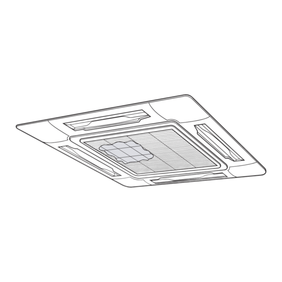
4-Way Cassette Type
MMU-AP0072H2UL-1
MMU-AP0072H2UL, MMU-AP0092H2UL,
MMU-AP0122H2UL, MMU-AP0152H2UL,
MMU-AP0182H2UL, MMU-AP0212H2UL,
MMU-AP0242H2UL, MMU-AP0302H2UL,
MMU-AP0362H2UL, MMU-AP0422H2UL
Compact 4-Way Cassette Type
MMU-AP0071MH2UL, MMU-AP0091MH2UL,
MMU-AP0121MH2UL, MMU-AP0151MH2UL,
MMU-AP0181MH2UL
Ceiling Type
MMC-AP0181H2UL, MMC-AP0241H2UL,
MMC-AP0361H2UL, MMC-AP0421H2UL
High Wall Type
MMK-AP0073H2UL, MMK-AP0093H2UL,
MMK-AP0123H2UL, MMK-AP0153H2UL,
MMK-AP0183H2UL, MMK-AP0243H2UL
4-Way Cassette Type
R410A
Compact 4-Way Cassette Type
FILE NO. A10-019
Revision 1 : Feb., 2013
Revision 2 : Sep., 2014
Revision 3 : Oct., 2014
Revision 4 : Jun., 2015
Revision 5 : Apr., 2016
Revision 6 : Jun., 2017
MULTI TYPE
Ceiling Type
High Wall Type
PRINTED IN JAPAN, Mar., 2011 ToMo
Advertisement
Table of Contents
Troubleshooting

Related Manuals for Toshiba MMU-AP0072H2UL-1


Summary of Contents for Toshiba MMU-AP0072H2UL-1
- Page 1 Revision 4 : Jun., 2015 Revision 5 : Apr., 2016 SERVICE MANUAL Revision 6 : Jun., 2017 AIR-CONDITIONER MULTI TYPE INDOOR UNIT 4-Way Cassette Type MMU-AP0072H2UL-1 MMU-AP0072H2UL, MMU-AP0092H2UL, MMU-AP0122H2UL, MMU-AP0152H2UL, MMU-AP0182H2UL, MMU-AP0212H2UL, MMU-AP0242H2UL, MMU-AP0302H2UL, MMU-AP0362H2UL, MMU-AP0422H2UL Compact 4-Way Cassette Type MMU-AP0071MH2UL, MMU-AP0091MH2UL,...
-
Page 2: Table Of Contents
CONTENTS SAFETY CAUTION ................3 1. SPECIFICATIONS ............... 8 2. CONSTRUCTION VIEWS (EXTERNAL VIEWS) ....... 11 3. WIRING DIAGRAM ..............23 4. PARTS RATING................. 27 5. REFRIGERATIN GCYCLE DIAGRAM ........29 6. CONTROL OUTLINE ..............30 7. APPLIED CONTROL AND FUNCTION ........46 8. -
Page 3: Safety Caution
SAFETY CAUTION The important contents concerned to the safety are described on the product itself and on this Service Manual. Please read this Service Manual after understanding the described items thoroughly in the following contents (Indications/Illustrated marks), and keep them. The manufacturer shall not assume any liability for the damage caused by not observing the description of this manual. - Page 4 WARNING Before troubleshooting or repair work, check the ground wire is connected to the ground terminals of the main unit, otherwise an electric shock is caused when a leak occurs. If the ground wire is not correctly connected, contact an electric engineer for rework. Check ground wires.
- Page 5 WARNING After the work has finished, be sure to use an insulation tester set (500V Megger) to check the resistance is 2MΩ or more between the charge section and the non-charge metal section (Ground position). If the resistance value is low, a disaster such as a leak or electric shock is caused at user’s Insulator check side.
-
Page 6: Safety Caution Concerned To New Refrigerant
• New Refrigerant (R410A) This air conditioner adopts a new HFC type refrigerant (R410A) which does not deplete the ozone layer. 1. Safety Caution Concerned to New Refrigerant The pressure of R410A is high 1.6 times of that of the former refrigerant (R22). Accompanied with change of refrigerant, the refrigerating oil has been also changed. - Page 7 4. Tools 1. Required Tools for R410A Mixing of different types of oil may cause a trouble such as generation of sludge, clogging of capillary, etc. Accordingly, the tools to be used are classified into the following three types. 1) Tools exclusive for R410A (Those which cannot be used for conventional refrigerant (R22)) 2) Tools exclusive for R410A, but can be also used for conventional refrigerant (R22) 3) Tools commonly used for R410A and for conventional refrigerant (R22) The table below shows the tools exclusive for R410A and their interchangeability.
-
Page 8: Specifications
(*1) The actual values in an external opeating environment are generally higher than the indicated values due to the contribution from ambient noise. • About the connection of MMU-AP0072H2UL-1, please refer to DATA BOOK of SMMS-e UL Model name MMU-... - Page 9 1-2. Compact 4-Way Cassette Type Model name MMU- AP0071MH2UL AP0091MH2UL AP0121MH2UL AP0151MH2UL AP0181MH2UL Cooling Capacity kBtu/h 15.4 Heating Capacity kBtu/h 10.5 13.5 Power supply 230 V (208/230V) 1 phase 60Hz Electrical characteristics Power consumption kW 0.034 0.036 0.038 0.041 0.052 Appearance (Celling panel)* Model RBC-UM11PG(W)-UL*...
- Page 10 1-4. High Wall Type Model name MMK- AP0073H2UL AP0093H2UL AP0123H2UL AP0153H2UL AP0183H2UL AP0243H2UL Cooling Capacity kBtu/h 15.4 Heating Capacity kBtu/h 10.5 13.5 Power supply 230 V (208/230V) 1 phase 60Hz Electrical characteristics Power consumption kW 0.018 0.021 0.021 0.043 0.043 0.05 Height 12.6...
-
Page 11: Construction Views (External Views)
2. CONSTRUCTION VIEWS (EXTERNAL VIEWS) 2-1. 4-Way Cassette Type MMU-AP0072H2UL-1, AP0072H2UL, AP0092H2UL, AP0122H2UL Unit: in (mm) - Page 12 MMU-AP0152H2UL, AP0182H2UL Unit: in (mm)
- Page 13 MMU-AP0212H2UL, MMU-AP0242H2UL, MMU-AP0302H2UL Unit: in (mm)
- Page 14 MMU-AP0362H2UL, MMU-AP0422H2UL Unit: in (mm)
- Page 15 2-2. Compact 4-Way Cassette Type MMU-AP0071MH2UL, MMU-AP0091MH2UL, MMU-AP0121MH2UL Unit: in (mm)
- Page 16 MMU-AP0151MH2UL, MMU-AP0181MH2UL Unit: in (mm)
- Page 17 2-3. Ceiling Type MMC-AP0181H2UL Unit: in (mm) 9.8"(250) or more 9.8"(250) or more (Front side to be positioned horizontally.) Space required for installation and servicing Upper pipe draw-out port(Knockout) Hole for remote control wires(Knockout) 8.3"(210) 8.5"(216) Pipe draw-out port(Knockout) Conduit hole 6.6"(167) (Hole for power supply cable, knockout) 2.0"...
- Page 18 MMC-AP0241H2UL Unit: in (mm) 9.8"(250) or more 9.8"(250) or more (Front side to be positioned horizontally.) Space required for installation and servicing Upper pipe draw-out port(Knockout) Hole for remote control wires(Knockout) 8.5"(216) Conduit hole 8.3"(210) (Hole for power supply cable, knockout) Pipe draw-out port(Knockout) 2.0"...
- Page 19 MMC-AP0361H2UL, MMC-AP0421H2UL Unit: in (mm) 9.8"(250) or more 9.8"(250) or more (Front side to be positioned horizontally.) Space required for installation and servicing Upper pipe draw-out port(Knockout) 8.3"(210) 8.5"(216) Pipe draw-out port(Knockout) Hole for remote control wires(Knockout) 6.6"(167) 4.3" 3.0" 2.5"...
- Page 20 2-4. High Wall Type MMK-AP0073H2UL, MMK-AP0093H2UL, MMK-AP0123H2UL Unit: in (mm)
- Page 21 MMK-AP0153H2UL, MMK-AP0183H2UL Unit: in (mm)
- Page 22 MMK-AP0243H2UL Unit: in (mm)
-
Page 23: Wiring Diagram
3. WIRING DIAGRAM 3-1. 4-Way Cassette Type MMU-AP0072H2UL-1, AP0072H2UL, AP0092H2UL, AP0122H2UL, AP0152H2UL, AP0182H2UL, AP0212H2UL, AP0242H2UL, AP0302H2UL, AP0362H2UL, AP0422H2UL... - Page 24 3-2. Compact 4-Way Cassette Type MMU-AP0071MH2UL, AP0091MH2UL, AP0121MH2UL, AP0151MH2UL, AP0181MH2UL...
- Page 25 3-3. Ceiling Type MMC-AP0181H2UL, AP0241H2UL, AP0361H2UL, AP0421H2UL...
- Page 26 3-4. High Wall Type MMK-AP0073H2UL, AP0093H2UL, AP0123H2UL, AP0153H2UL, AP0183H2UL, AP0243H2UL...
-
Page 27: Parts Rating
4. PARTS RATING 4-1. 4-Way Cassette Type Model MMU- AP007 AP009 AP012 AP015 AP018 AP021 AP024 AP030 AP036 AP042 ICF-340 Fan motor SWF-340U60-2 U150-1 Moter for horizontal grille MP24ZN3N Pulse motor EFM-MD12TF-1 EDM-B60 Pulse motor valve EDM-B40YGTF-2 YGTF-1 TA sensor Lead wire length : 12.2 in (310 mm) Vinyl tube TC1 sensor Ø4 size lead wire length : 47.24 in (1200 mm) Vinyl tube (Blue) - Page 28 4-3. Ceiling Type Model MMC- AP0181H2UL AP0241H2UL AP0361H2UL AP0421H2UL Fan motor SWF-340U60-1A SWF-340U60-2A SWF-340U120-2A Driving motor for horizontal grille MP24Z2 Pulse motor EFM-MD12TF-1 Pulse motor valve EBM-B40YGTF- 3 EDM-B60YGTF-1 TA sensor Lead wire length : 6.1 in (155 mm) Vinyl tube TC1 sensor Ø4 size lead wire length : 47.24 in (1200 mm) Vinyl tube (Blue)
-
Page 29: Refrigeratin Gcycle Diagram
5. REFRIGERATING CYCLE DIAGRAM Liquid side Gas side Strainer Capillary tube Air heat exchanger at indoor side Pulse Motor Valve (PMV) Strainer Sensor (TCJ) Sensor (TC2) Sensor (TC1) Sensor Fan motor (TA) Functional part name Functional outline Pulse Motor Valve (Connector CN082 (6P): Blue) 1) Controls super heat in cooling operation 2) Controls under cool in heating operation... -
Page 30: Control Outline
6. CONTROL OUTLINE 6-1. 4-Way Cassette Type, Compact 4-Way Type, Ceiling Type Item Outline of specifications Remarks When power 1) Distinction of outdoor unit supply is reset When the power supply is reset, the outdoors are distinguished and the control is selected according to the distinguished result. - Page 31 Item Outline of specifications Remarks Automatic 1) Based on the difference between Ta and Ts, the capacity control operation capacity is determined by the outdoor unit. COOL HEAT ˚F (˚C) ˚F (˚C) +3.6 (+2) +1.8 (+1) +1.8 (+1) Ts: Setup temp. Ta: Room temp.
- Page 32 Item Outline of specifications Remarks Air speed <HEAT> selection (Continued) Ta ˚F [˚C] L <L+> (–0.9) Ð1.8 [(–0.5) –1.0] L+ <H> (0) Tsh H <H+> (+0.9) +1.8 [(+0.5) +1.0] <HH> (+1.8) +3.6 [(+1.0) +2.0] (+2.7) +5.4 [(+1.5) +3.0] <HH> (+3.6) +7.2 [(+2.0) +4.0] <...
- Page 33 Item Outline of specifications Remarks Freeze prevention 1. In all cooling operation, the air conditioner TC1: Temperature of indoor control operates as de-scribed below based upon temp. heat exchanger sensor (Low temp. release) detected by TC1, TC2 and TCJ sensors. •...
- Page 34 Item Outline of specifications Remarks Recovery control The indoor unit which is under STOP/Thermo-OFF • The indoor unit which is for heating status or which operates in [FAN] mode performs the under thermo-OFF (COOL) refrigerant (Oil) following controls when it received the heating status or which operates in refrigerant (Oil) recovery signal from the outdoor unit.
- Page 35 Item Outline of specifications Remarks Display of < READY> Displayed on the remote control • <READY > display [READY] 1) When the following check codes are indicated No display for wireless [HEAT READY] type remote control • Open phase of power supply wiring [P05] was detected. •...
- Page 36 Item Outline of specifications Remarks Louver control: 1) Louver position setup The louver position at In case of 4-way horizontal discharge position • When the louver position is changed, the position moves Cassette type at under AP030 differs from necessarily to downward discharge position once to return and ceiling type that at over AP036.
- Page 37 Item Outline of specifications Remarks Louver contro <<Selection of Swing mode>> (Continued): • For the Swing mode, the following three types of modes On the remote control In case of are selectable and settable by keeping Swing/Direction before the wired remote SWING/FIX 4-way Cassette button pushed for 4 seconds or more on the remote...
- Page 38 Item Outline of specifications Remarks Louver control • If there is the locked louver in the unit, [ ] goes on the For the setting operation, refer to [How to set louver remote control screen. (Continued): lock] of Installation Manual. In case of 4-way •...
- Page 39 6-2. High Wall Type Item Outline of specifications Remarks When power 1) Distinction of outdoor unit supply is reset When the power supply is reset, the outdoors are distinguished and the control is selected according to the distinguished result. 2) If resetting the power supply during occurrence of a trouble, the check code is once cleared.
- Page 40 Item Outline of specifications Remarks Prevention of cold 1. In heating operation, the higher temperature of TC2 TCJ: Temperature of indoor sensor and TCJ sensor is compared with temperature air discharge heat exchanger sensor of TC1 sensor and then the lower temperature is •...
- Page 41 Item Outline of specifications Remarks Recovery control for The indoor unit which is under STOP/Thermo-OFF • Recovery operation is cooling oil status or which operates in [FAN] mode performs the usually performed every (Refrigerant) following controls when it received the cooling oil 2 hours 5 minutes.
- Page 42 Item Outline of specifications Remarks Display of <OPERATION READY> Displayed on the remote control • < > display OPERATION 1) When the following check codes are indicated No display for wireless READY] remote control • Open phase of power supply wiring [P05] was detected. PRE-HEAT] •...
- Page 43 Item Outline of specifications Remarks Louver control 1) Louver position setup (Wired type) • The louver position can be set up in the following operation range. In cooling/dry operation In heating/fan operation • In group operation, the louver positions can be set up collec- tively or individually.
- Page 44 Item Outline of specifications Remarks COMFORT When you push the COMFORT SLEEP button during cooling, • [ ] display SLEEP operation heating or A operation, the air conditioner will start the following (Wireless remote operation. control specific The fan speed display will indicate AUTO and low speed will be used. operations) •...
- Page 45 Item Outline of specifications Remarks QUIET operation When you push the QUIET button during cooling, • [ ] display (Wireless remote heating, fan only or A operation, the air conditioner will control specific start the following operation. operation) • The fan speed display will indicate AUTO and low speed will be used.
-
Page 46: Applied Control And Function
7. APPLIED CONTROL AND FUNCTION 7-1. Indoor Control Block Diagram 7-1-1. When Main (Simple) Wired Remote Control Connected 4-Way Cassette Type... - Page 47 Compact 4-Way Casstte Type, Ceiling Type...
- Page 48 High Wall Type Main (Simple) wired remote control (Up to 2 sets) Display part Function setup Key switch Display part DC5V Power circuit Remote control communication circuit Indoor unit Main P.C. board (MCC-1510) DC20V Remote control communication circuit Central control EEPROM communication circuit TA sensor...
- Page 49 7-1-2. When Wireless Remote Control Kit Connected 4-Way Cassette Type...
- Page 50 Compact 4-Way Cassette Type, Ceiling Type...
- Page 51 7-1-3 . When Both wired (Simple) Remote Control and Wireless Remote Control Kit Connected 4-Way Cassette Type...
- Page 52 Compact 4-Way Cassette Type, Ceiling Type...
- Page 53 7-2. IndoorPrinted Circuit Board MCC-1570 4 -WayCasstte Type...
- Page 54 MCC-1402 Compact 4-WayCasstte Type, Ceiling Type...
- Page 55 7-3. P.C. Board Optional Connector Specifications...
- Page 56 MCC-1510 High Wall Type...
- Page 57 High wall type P.C. Board Optional Switch/Connector Specifications Connector Function Specifications Remarks Terminator resistor OFF: No terminator resistor, Setup at shipment OFF: No terminator resistor. Bit 1 provided/Not provided ON: Terminator resistor provided Only 1 unit is ON during central control by custom only. SW01 OFF: Remote control A Remote control A/B...
- Page 58 7-3. Functions at test run Cooling/Heating test run check The test run for cooling/heating can be performed from either indoor remote control or outdoor interface P.C. board. 1. Start/Finish operation of test run Test run from indoor remote control Wired remote control: Refer to the below item of “Test run” of the wired remote control. Wireless remote control: Refer to the next page item of “Test run”...
- Page 59 <In case of wireless remote control> 1. When TEMPORARY button is pushed for 10 seconds or more, “Pi!” sound is heard and the operation changes to a forced cooling operation. After approx. 3 minutes, a cooling operation starts forcedly. Check cool air starts blowing. If the operation does not start, check wiring again. 2.
- Page 60 Check function for operation of indoor unit (Functions at indoor unit side) This function is provided to check the operation of the indoor unit singly without communication with the remote control or the outdoor unit. This function can be used regardless of operation or stop of the system. However, if using this function for a long time, a trouble of the equipment may be caused.
-
Page 61: Method To Set Indoor Unit Function Dn Code
7-4. Method to Set Indoor Unit Function DN Code (When performing this task, be sure to use a wired remote control.) <Procedure> To be performed only when system at rest Push the buttons simultaneously and hold for at least 4 seconds. The unit No. - Page 62 Functio n CODE No. (DN Code) Table (Includes All Functions Needed to Perform Applied Control on Site) Item Descrip tio n At sh ip men t Filter display delay timer 0000: None 0001: 150H According to type 0002: 2500H 0003: 5000H 0004: 10000H Dirty state of filter 0000: Standard...
- Page 63 Item Description At shipment High-ceiling adjustment 0000: Standard (Air flow selection) 4-way Cassette Type AP036, AP042 AP007, AP009, AP012 AP015, AP018 AP021, AP024, AP030 Value Air flow at outlet 4-Way 3-Way 2-Way 4-Way 3-Way 2-Way 2-Way 4-Way 3-Way 2-Way 4-Way 3-Way Standard 9'2"...
- Page 64 7-5. Applied Control in Indoor Unit Remote location ON/OFF control box (TCB-IFCB-4UL) [Wiring and setup] • Use the exclusive connector for connection with the indoor control P.C. board. • In a group control, the system can operate when connecting with any indoor unit (Control P.C. board) in the group.
- Page 65 Ventilating fan control from remote control [Function] • The start/stop operation can be operated from the wired remote control when air to air heat exchanger or ventilating fan is installed in the system. • The fan can be operated even if the indoor unit is not operating. •...
- Page 66 Leaving-ON prevention control [Function] • This function controls the indoor units individually. It is connected with cable to the control P.C. board of the indoor unit. • In a group control, it is connected with cable to the indoor unit (Control P.C. board), and the CODE No. 2E is set to the connected indoor unit.
- Page 67 Address setup (Manual setting from Wired remote control) In case that addresses of the indoor units will be determined prior to piping work after wiring work (Example of 2-lines cabling) • Set an indoor unit per a remote control. (Real line: Wiring, Broken line: Refrigerant pipe) •...
- Page 68 Confirmation of indoor unit No. position 1. To know the indoor unit addresses though position of the indoor unit is recognized • In case of individual operation (Wired remote control : indoor unit = 1 : 1) (Follow to the procedure during operation) <Procedure>...
- Page 69 How to check all the unit No. from an arbitrary wired remote control <Procedure> Carry out this procedure during stop of system. The indoor unit No. and the position in the identical refrigerant piping can be checked. An outdoor unit is selected, the identical refrigerant piping and the indoor unit No. are displayed one after the other, and then its fan and louver are on.
- Page 70 How to change an indoor unit address by using a wired remote control Use this method to change the address of indoor units (one to one or group control) that have had the original address set automatically. This procedure must be done while the units are not operating. Simultaneously push and hold the “SET ”, “CL ”, and “TEST...
- Page 71 How to change all indoor addresses from an arbitrary wired remote control (It is possible when setting has finished by automatic addresses.) Contents: The indoor unit addresses in each identical refrigerant piping line can be changed from an arbitrary wired remote control. Enter in address check/change mode and then change the address.
- Page 72 Function to clear trouble 1. Clearing method from remote control How to clear trouble of outdoor unit In the unit of refrigerant line connected by indoor unit of the remote control to be operated, the trouble of the outdoor unit currently detected is cleared. (Trouble of the indoor unit is not cleared.) The service monitor function of the remote control is utilized.
- Page 73 Monitoring function of remote control switch When using the remote control (Model Name: RBC-AMT32UL), the following monitoring function can be utilized. Calling of display <Contents> The temperature of each sensor of the remote control, indoor unit and outdoor unit and the operating status can be checked by calling the service monitor mode from the remote control.
- Page 74 < Based on the SMMS-e > CODE No. Data name Display format Unit Remote control display example Room temperature (Use to control) ×1 °C [0027] = 27 °F Room temperature (Remote control) ×1 °C Indoor suction air temperature (TA) ×1 °F Indoor coil temperature (TCJ) ×1...
- Page 75 LED display on P.C. board (MCC-1570, 4-Way Casstte Type only) 1. D501 (Red) • D501 goes on at the same time when the power supply is turned on. (Goes on with operation of the main microprocessor) • D501 flashes with 1-second interval (every 0.5 second) : When there is no EEPROM or write-in trouble •...
- Page 76 Changing of settings for Celsius display • Push button if the unit stops. ON / OFF Procedure Push simultaneously buttons for 4 seconds or more. TEST After a while, the display part flashes as shown right. Check the displayed CODE No. is [10]. •...
-
Page 77: Troubleshooting
8. TROUBLESHOOTING 8-1. Overview (1) Before engaging in troubleshooting (a) Applicable models All Super Module Multi (SMMS-i, SMMS-e, SHRM-e) models. ∗ ∗∗∗ ∗∗∗ (Indoor units: MM , Outdoor units: MMY-MAP (b) Tools and measuring devices required • Screwdrivers (Philips, flat head), spanners, long-nose pliers, nipper, pin to push reset switch, etc. •... -
Page 78: Troubleshooting Method
8-2. Troubleshooting Method The remote controls (main remote control and central control remote control) and the interface P.C. board of an outdoor unit are provided with an LCD display (remote control) or a 7-segment display (outdoor interface P.C. board) to display operational status. Using this self-diagnosis feature, the problem site/problem part may be identified in the event of a problem by following the method described below. - Page 79 (Trouble detected by main remote control) Check code Display of receiving unit Outdoor 7-segment display Indicator light block Typical fault site Description of trouble Main remote control Operation Timer Ready Flash Sub-code No master remote control, Signals cannot be received from indoor unit; –...
- Page 80 List of Check Codes (Outdoor Unit) (Check code detected by SMMS-e outdoor interface - typical examples) If “HELLO” is displayed on the oudoor 7-segment for 1 minute or more, turn off the power supply once and then turn on the power supply again after passage of 30 seconds or more.
- Page 81 Check code Display of receiving unit Outdoor 7-segment display TCC-LINK Indicator light block central control Typical problem site Description of problem or main remote Operation Timer Ready Sub-code Flash control display Outdoor heat exchanger Outdoor heat exchanger gas side temperature 01: TG1 gas side temperature sensors (TG1, TG2) have been open/...
- Page 82 Check code Display of receiving unit Outdoor 7-segment display TCC-LINK Indicator light block central control Typical problem site Description of problem or main remote Operation Timer Ready Sub-code control Flash display A3-IPDU Fan-IPDU A3-IPDU Fan-IPDU There are insufficient number of IPDUs (P.C. Trouble in number IPDUs boards) in inverter box.
- Page 83 (Check code detected by IPDU featuring in SMMS-e standard outdoor unit - typical examples) Check code Display of receiving unit Outdoor 7-segment display TCC-LINK Indicator light block central control Typical problem site Description of proplem or main remote Operation Timer Ready Sub-code Flash control...
- Page 84 8-3. Troubleshooting Based on Information Displayed on Remote Control Using main remote control (RBC-AMT32UL) (1) Checking and testing When a fault occurs to an air conditioner, a check code and indoor unit No. are displayed on the display window of the remote control. Check codes are only displayed while the air conditioner is in operation.
- Page 85 Using indoor unit indicators (receiving unit light block) (wireless type) To identify the check code, check the 7-segment display on the header unit. To check for check codes not displayed on the 7-segment display, consult the “List of Check Codes (Indoor Unit)” in “8-2. Troubleshooting Method”. : Goes off : Lighting : Blinking (0.5 seconds)
- Page 86 Heat exchanger temperature sensor (TCJ) trouble Operation Timer Ready Heat exchanger temperature sensor (TC2) trouble Indoor unit temperature sensor Heat exchanger temperature sensor (TC1) trouble troubles Ambient temperature sensor (TA/TSA) trouble Alternate blinking Discharge temperature sensor (TF) trouble Discharge temperature sensor (TD1) trouble Operation Timer Ready Discharge temperature sensor (TD2) trouble...
- Page 87 Light block Check code Cause of fault Operation Timer Ready Outdoor EEPROM trouble Synchronized blinking Other (indications not involving check code) Light block Check code Cause of fault Operation Timer Ready – Test run in progress Synchronized blinking Operation Timer Ready Setting incompatibility –...
- Page 88 8-4. Check Codes Displayed on Remote Control and SMMS-e Outdoor Unit (7-Segment Display on I/F Board) and Locations to Be Checked For other types of outdoor units, refer to their own service manuals. Check code Location Trouble detection Main Outdoor 7-segment display Description System status Check items (locations)
- Page 89 Check code Location Trouble detection Main Outdoor 7-segment display Description System status Check items (locations) condition(s) remote detection Check Sub-code control code Too many All stop • Combined capacity of indoor units • Check capacities of indoor units Overloading indoor units exceeds 135% of combined connected.
- Page 90 Check code Location Trouble detection Main Outdoor 7-segment display Description System status Check items (locations) condition(s) remote detection Check Sub-code control code IPDU All stop Communication is disrupted • Check wiring and connectors A3-IPDU Fan-IPDU communication between IPDUs (P.C. involved in communication trouble boards) in inverter box.
- Page 91 Check code Location Trouble detection Main Outdoor 7-segment display Description System status Check items (locations) condition(s) remote detection Check Sub-code control code 01: TS1 sersor trouble TS1/TS2 All stop Sensor resistance is infinity or zero • Check connection of TS1/TS3 03: TS2 sersor trouble sensor trouble (open/short circuit).
- Page 92 Check code Location Trouble detection Main Outdoor 7-segment display Description System status Check items (locations) condition(s) remote detection Check Sub-code control code Activation of All stop Low-pressure Ps sensor detects • Check service valves to confirm low-pressure operating pressure lower than full opening (both gas and liquid protection 0.02MPa.
- Page 93 Check code Location Trouble detection Main Outdoor 7-segment display Description System status Check items (locations) condition(s) remote detection Check Sub-code control code 01: TK1 oil circuit trouble Oil level All stop No temperature change is detected • Check for disconnection of TK1 02: TK2 oil circuit trouble detection by TK1 despite compressor 1...
- Page 94 Check code Location Trouble detection Main Outdoor 7-segment display Description System status Check items (locations) condition(s) remote detection Check Sub-code control code Indoor Indoor capacity Stop of Capacity setting has not been Set indoor capacity. (DN = 11) — — unit not set corresponding...
- Page 95 Check code Location Trouble detection Main Outdoor 7-segment display Description System status Check items (locations) condition(s) remote detection Check Sub-code control code 01: Compressor 1 side IPDU Activation of All stop High-pressure SW is activated. • Check connection of highpressure 02: Compressor 2 side high-pressure SW connector.
- Page 96 Check code Location Trouble detection Main Outdoor 7-segment display Description System status Check items (locations) condition(s) remote detection Check Sub-code control code 01: TS condition All stop Protective shutdown due to • Check for insufficiency in leakdetection sustained suction temperature at or refrigerant quantity.
- Page 97 Check code Location Trouble detection Main Outdoor 7-segment display Description System status Check items (locations) condition(s) remote detection Check Sub-code control code #0:Element short circuit IPDU Outdoor fan All stop (Sub code: #0) • Check fan motor. IPDU trouble Fan IPDU over current protection •...
- Page 98 8-5. Sensor Characteristics Indoor Unit Temperature sensor characteristics Temperature Resistance [˚F (˚C)] [kΩ] Resistance 32 (0) 33.9 [kΩ] 41 (5) 26.1 50 (10) 20.3 59 (15) 15.9 68 (20) 12.6 77 (25) 10.0 86 (30) 95 (35) 104 (40) 113 (45) 122 (50) 131 (55) 140 (60)
-
Page 99: Detachments
9. DETACHMENTS 9-1. 4-Way Cassette Type WARNING Be sure to turn off the power supply and the breaker and then start a work. CAUTION Be sure to put on the gloves at disassembling work; otherwise an injury will be caused by a part, etc. Part name Procedure Remarks... - Page 100 Part name Procedure Remarks 1. Detachment Electric parts cover Bell mouth pin Claw of 1) Carry out work of Detachment of electric parts box Potbelly hole 2) Remove the fixing screw “A” which fixes (Dharma doll hole) the electric parts cover and loosen the fixing screw “B”.
- Page 101 Part name Procedure Remarks 1. Detachment Adjust corner Knob 1) Pull knob of the adjust corner cap to the arrow direction, remove strap of the Pulling direction Pulling direction Pulling direction adjust corner cap from pin of the panel and then remove all the 4 corners of the cap.
- Page 102 Part name Procedure Remarks 1. Detachment Ceiling panel Clamp 1) Carry out works of Detachment of Louver motor wiring Louver motor wiring Louver motor wiring 2) Remove the louver connector (CN510, White, 20P) connected to the control P.C. board and then remove the lead wire from the clamp.
- Page 103 Part name Procedure Remarks 1. Detachment Control P.C. board 1) Carry out work of Detachment of Clamp 2) Remove connectors which are connected from the control P.C. board to the other parts and then remove wiring from the clamp. CN510 : Louver motor (20P, White) CN34 : Float switch (3P, Red) CN504 : Drain pump (2P, White) CN100 : TC1 sensor (3P, Brown)
- Page 104 Part name Procedure Remarks 1. Detachment Drain cap Drain cap (outside) 1) Carry out work of Detachment of 2) Loosen screws (3 positions) fixing the drain cap (outside) and then turn the drain cap to the arrow mark → (OPEN) direction to remove it.
- Page 105 Part name Procedure Remarks 1. Detachment Fan motor Fixing screw A Fixing screw A Fixing screw A 1) Carry out work of Detachment of 2 . 2) Remove the power supply wire and the remote control wire from the power supply terminal block and the remote control terminal block each.
- Page 106 Part name Procedure Remarks Fan motor 7) Remove the fixing screws and then remove Bell mouth Bell mouth Nut cap Nut cap (Continued) the bell mouth. (M4, 0.39"(10 mm), 8 pcs.) 8) Remove the fixing screws and then remove the nut cap. (M4, 0.39"(10 mm), 2 pcs.) 9) Remove the fixing nut and then remove the turbo fan.
- Page 107 Part name Procedure Remarks 1. Detachment Drain pump Fixing screw “A” 1) Carry out works of Detachment of 2) Remove the drain pump connector Drain port Drain port Drain port (CN504, White, 2P) connected to the control P.C. board and then remove the lead wire from the clamp.
- Page 108 Part name Procedure Remarks 1. Detachment Float switch assembly 1) Carry out works of Detachment of Float switch assembly Float switch assembly Float switch assembly works from 1) to 7). 2) Remove the fixing screw and then remove the float switch assembly. (M4,0.98" (25 mm), 1 pc.)) 2.
- Page 109 Part name Procedure 1. Detachment PMV motor 1) Carry out work of 1.Detachment of PMV body PMV motor 2) Remove the relay connector of PMV motor. 3) Peel the butyl rubber adhered to the main unit of the pulse motor valve (PMV) until PMV can be seen and then loosen the nuts fixing PMV motor with double spanner to remove PMV motor.
- Page 110 Part name Procedure Remarks 1. Detachment Heat exchanger 1) Recover the refrigerant gas. 2) Carry out work of Detachment of 3) Remove refrigerant pipe at indoor unit side. 4) Remove the fixing screws and then remove the piping cover. (M4, 0.39" (10 mm), 3 pcs.)) 5) Remove the drain hose from the drain pump and remove the fixing screws “A”...
- Page 111 9-2. Compact 4-Way Cassette Type Preparing work: 1. Before work, be sure to stop the power supply of the air conditioner and turn off switch of the power supply breaker. (Otherwise an electric shock may be caused.) 2. Be sure to put on the gloves when working; otherwise an injury may be caused with parts sharp edges etc. Part name Procedure Remarks...
- Page 112 Part name Procedure Remarks 1. Detachment Adjust corner cover 1) Perform work of procedure of 1 -1. 2) Turn clockwise screws (4 positions) at the suction port corner until adjust corner cover rises up. NOTE) When you work, keep the torque at below 8.9ft .
- Page 113 Part name Procedure Remarks 1. Detachment Control P.C. board 1) Perform works of procedure 2 -1. 2) Remove the connectors connected from the control P.C. board to other parts. CN33 : Flap motor (5P, White) CN34 : Float switch (3P, Red) CN41 : Terminal block of remote control (3P, Blue) CN40 : Terminal block of crossover between inside and outside (2P, Blue) CN68 : Drain pump (3P, Blue)
- Page 114 Part name Procedure Remarks Electric 1. Detachment parts box 1) Perform works of procedure 4 -1. 2) Remove connectors of the lead wire connected to the following connectors of the control P.C. board. CN33 : Flap motor (5P, White) CN34 : Float switch (3P, Red) CN68 : Drain pump (3P, Blue) CN100 : TC1 sensor (3P, Brown) CN101 : TC2 sensor (2P, Black)
- Page 115 Part name Procedure Remarks 1. Detachment Fan guard 1) Perform work of procedure 1 -1. Clamp Fan guard 2) Take off screws and clamp fixing the fan guard. (Ø4 × 0.39"(10mm), [Screws for plastic molding] 3 pcs.)) NOTE) The specification of fixing screws for the fan guard differs from those of other fixing screws.
- Page 116 Part name Procedure Remarks 1. Detachment Fan motor Fixing nut for fan motor 1) Perform work of procedure 9 . 2) Take off screws fixed with lead holding bracket of the fan motor. (Ø4 × 0.31"(8mm), 2 pcs.)) 3) Open wiring holding part of the fan motor lead holding bracket and then take off the fan motor lead wire from the bracket.
- Page 117 Part name Procedure Remarks 1. Detachment Drain pan 1) Perform works of procedure 4 -1 and 8 -1. 2 screws 2) Remove the drain cap and extract drain water accumulated in the drain pan. NOTE) Socket of drain pan Socket of drain pan Socket of drain pan When removing the drain cap, be sure to receive drain water with a bucket, etc.
- Page 118 Part name Procedure Remarks 1. Detachment (Pulse Motor Valve) 1) Perform work of procedure 11 -1. 2) Take off screws (Ø4 × 0.31"(8mm), 3 pcs.)) fixing the piping cover to remove the piping cover. 3) Cut off binding band that binds the PMV lead wires.
- Page 119 Part name Procedure Remarks 1. Detachment Heat exchanger 1) Recover refrigerant gas. 2) Remove the refrigerant pipe at indoor unit side. 3) Perform work of procedure 11 -1. 4) Take off screws (Ø4 × 0.31"(8mm), 3 pcs.)) fixing the piping cover to remove the piping cover.
- Page 120 9-3. Ceiling Type WARNING Stop the operation of the air conditioner and then turn off switch of the breaker. CAUTION Be sure to put on the gloves at disassembling/assembling work; otherwise an injury will be caused by a part, etc. Part name Procedure Remarks...
- Page 121 Part name Procedure Remarks 1. Detachment Electric parts cover 1) Carry out work of Detachment of Clamps 2) Remove the screws (2 pcs.) which are fixing the fan guard. CAUTION Remove the 2 screws fixing the fan guard and hang the fan guard with the clamps during a service.
- Page 122 Part name Procedure Remarks 1. Detachment Electric parts box 1) Carry out works of Detachment of 2) Remove the power supply wire and the remote control wire and control wires from Power supply the terminal blocks. terminal block Control wiring/Remote control terminal block 3) Remove the power supply wire from cord Cord clamp...
- Page 123 Part name Procedure Remarks 1. Detachment Control P.C. board 1) Carry out works of Detachment of and 3 . Card edge spacer Ground wire of P.C. board 2) Remove connectors and ground wire which are connected from the control P.C. board to other parts.
- Page 124 Part name Procedure Remarks Fan, Shaft, Fan quantity and mounting construction Bearing, Coupling, Model name Quantity Mounting construction Hooking claw Hooking claw Hooking claw Fan case Direct mounting to both sides of AP180 SP180CT-UL 2 fans fan motor Shaft is used and one side of AP240 SP240CT-UL 3 fans...
- Page 125 Part name Procedure Remarks 2. Attachment Fan, Shaft, Bearing, 1) Mount a fan to the shaft. Refereeing to the Arrange so that screws are at right side Arrange so that screws are at right side Arrange so that screws are at right side Coupling, against the bottom make-up panel.
- Page 126 Part name Procedure Remarks 1. Detachment Fan motor Fan motor 1) Carry out works of Detachment of 2) Remove wires and connectors which are connected from the control P.C. board to the fan motor. NOTE : Release the lock of the housing part and then remove the connectors.
- Page 127 Part name Procedure Remarks 1. Detachment Fan guard 1) Carry out work of Detachment of Clamps 2) Remove the screws (2 pcs.) which are fixing the fan guard. 3) Remove the fan guard by removing screws which fix the clamp. 2.
- Page 128 Part name Procedure Remarks 1. Detachment Drain pan 1) Carry out work of Detachment of 2) Take off the drain cap and then extract drain water accumulated in the drain pan. Drain hose Drain hose Drain hose NOTE : When taking off the drain cap, be sure to receive drain water by a bucket, etc.
- Page 129 Part name Procedure Remarks 1. Detachment Heat exchanger Screws 1) Recover the refrigerating gas. 2) Remove the refrigerant pipe at the indoor unit side. 3) Perform the detachment work in Remove also the sensors. 4) Take off screws which fix the piping cover and then remove the piping cover.
- Page 130 Part name Procedure Remarks 1. Detachment Louver motor, Screws Louver drive 1) Carry out work of Detachment of (Fixing louver drive member and main unit) member 2) Remove connectors of the louver motor lead wire. 3) Remove the set screws (2 positions) Louver drive Louver drive Louver drive...
- Page 131 9-4. High Wall Type Part name Procedures Remarks Front panel 1) Stop operation of the air conditioner and turn off its main power supply. 2) Open the air inlet grille, push the arm toward the outside, and remove the grille. 3) Push “PUSH”...
- Page 132 Part name Procedures Remarks Electric parts 1) Perform work of item assembly PMV cover PMV cover PMV cover 2) Take off PMV cover fixing screws (2 pcs.) and then remove PMV cover. 3) Take off drain guide fixing screws (2 pcs.) and then remove the drain guide.
- Page 133 Part name Procedures Remarks <Cautions at work> <AP0243 to AP0153> PMV motor Spanner push-in part Using spanners by 0.67" (17mm) and 0.75" (Main unit side: 0.67"(17 mm)) (19mm), remove the PMV motor. <AP0243 to AP0153> Using spanners by 0.63" (16mm) and 0.75" (19mm), remove the PMV motor.
- Page 134 Part name Procedures Remarks Evaporator 1) Follow to the procedure in the item ‚ . (Heat exchanger) 2) Remove the pipe holder from the rear side of the main unit. 3) Remove 2 fixing screws at the left side of the end plate of the heat exchanger. 2 screws <AP0243 to AP0153>...
- Page 135 Part name Procedures Remarks Bearing 1) Follow to the procedure in the item 2) Remove the 2 screws used to secure the bearing base. 3) Remove the bearing base. 2 screws Bearing base <Caution at assembling> • If the bearing is out from the housing, push it into the specified position and then incorporate it in the main body.
- Page 136 Part name Procedures Remarks Fan motor 1) Follow to the procedure till item 2) Loosen the set screw of the cross flow fan. 3) Remove 2 fixing screws of the motor cover and them remove the motor cover. 4) Remove 2 more fixing screws of the motor band and remove the motor band.
- Page 137 Part name Procedures Remarks <Caution at reassembling> Cross flow 1) To incorporate the fan motor, remove the fan motor rubber (at shaft core side), incorporate the motor into the position in the following figure, and then install the fan motor. 0.2"(5.0mm) •...
-
Page 138: Board Exchange Procedures
10. P.C. BOARD EXCHANGE PROCEDURES 10-1. 4-Way Cassette type , Compact 4-Way Cassette type, Ceiling type Part code Model type P.C. board type 431-6V-447 MMU-AP MCC-1570 2H2UL series MMU-AP 1MH2UL series MCC-1402 431-6V-445 MMC-AP 1H2UL series Points to Note When Replacing Indoor P.C. Board Assembly The electrically erasable programmable read-only memory (hereinafter EEPROM,IC503, or IC10) mounted on an indoor P.C. - Page 139 Procedure 1: Reading Setting Data from EEPROM (Read the setting data from EEPROM, including both the factory settings and any modifications made to them on site.) Push the buttons simultaneously and hold for at least 4 seconds. (This number corresponds to the same number shown on the Remote Control Operation Diagram.) * In the case of group control, the unit No.
- Page 140 Procedure 2: Replacing P.C. Board Replace the faulty P.C. board with a service P.C. board. Be sure to replicate the old jumper setting (removal), switch setting (SW501), and connector short-circuit setting (e.g. CN34) on the service P.C. board. (See the diagram at below.) (MCC-1570) The type and capacity of the indoor unit are necessary for fan speed setting.
- Page 141 ” to the CODE No. (DN). 0000 0001 (2) Using the timer time buttons, set (initial) to “ ”. Setting for MMU-AP0072H2UL-1 only (1) Using the set temperature buttons, set “ ” to the CODE No. (DN). 0000 0001 (2) Using the timer time buttons, set (initial) to “...
- Page 142 Tabel 1 CODE No. list (Example) CODE No. (DN) Item Setting data Factory-set value Filter sign lighting time Depending on Type Filter pollution leve 0000: standard Central control address 0099: Not determined Heating suction temperature shift 0002: + 3.6°F(+ 2°C) Cooling only 0000: Heat pump Type...
- Page 143 10.2 High Wall type In the non-volatile memory (Hereinafter said EEPROM, IC10) installed on the indoor P.C. board before Part code Model type P.C. board model MMK-AP 3H2UL series 43T69906 MCC-1510 replacement, the type and capacity code exclusive to the corresponding model have been stored at shipment from the factory and the important setup data such as refrigerant line /indoor unit /group address in (AUTO/MANUAL) mode have been stored at installation.
- Page 144 UNIT LOUVER 2. Every pushing button (button of left side), the indoor unit address in the group are displayed succes- sively. Specify the indoor unit No. to be replaced. 3. Using the set temperature buttons, the CODE No. (DN) can be moved up and down one by one. 10 10 10 10 10 01 01 01 01 01 4.
- Page 145 CASE 2 C) In case that power of the indoor units cannot be turned in individually. ( a) Remove all CN41 connectors of the indoor units in the same group except those of the exchanged indoor unit. b) Turn on power of the indoor units and proceed to Procedure 3 ∗...
- Page 146 Procedure2: 3 Writing of the setup contents to EEPROM (The contents of EEPROM installed on the service P.C. board have been set up at shipment from the factory.) TEST 1. Push buttons of the remote control at the same time for 4 seconds or more. (Corresponded with No.
- Page 147 Table 2 CODE No. table (Please record the objective unit data at field) Item Memo At shipment Filter sign lighting time 0001: 150 hour Dirty state of filter 0000: Standard Central control address 0099: Unfixed Heating suction temp shift 0002: + 3.6°F (+2°C) PRE-DEF indication selection 0000: Standard Cooling only...
-
Page 148: Exploded Views And Parts List
11. EXPLODED VIEWS AND PARTS LIST 1.1 4-Way Cassette Type MMU-AP0072H2UL, AP0092H2UL, AP0122H2UL... - Page 149 Model Name MMU-AP Location Description Parts No. 0072H2UL 0092H2UL 0122H2UL 43120248 FAN, ASSY TURB 43166013 REMOTE CONTROLLER, SX-TA01UE 43166014 REMOTE CONTROLLER, SX-TB01UE 43122110 BELL MOUTH 43172213 PAN ASSY, DRAIN 43172254 PAN ASSY, DRAIN 4314J531 REFRIGERATION CYCLE ASSY 4314J532 REFRIGERATION CYCLE ASSY 43146707 MOTOR, PMV, EDM-MD12TF-3 43146713...
- Page 150 MMU-AP0072H2UL, AP0092H2UL, AP0122H2UL Model Name MMU-AP Location Parts No. Description 0072H2UL 0092H2UL 0122H2UL 43050425 Sensor Ass’y, Service, TC (F6) : TC2, TCJ 43F50426 Sensor, Service, TA 43150320 Sensor Ass’y, Service, TG (F4) : TC1 43160574 Terminal, 4P 43160626 Terminal Block, 2P, 20A 4316V447 P.C.
- Page 151 MMU-AP0072H2UL-1...
- Page 152 Q'ty/Set Location Description Parts No. MMU-AP0072H2UL-1 43120248 FAN, ASSY TURB 43166013 REMOTE CONTROLLER, SX-TA01UE 43166014 REMOTE CONTROLLER, SX-TB01UE 43122110 BELL MOUTH 43172213 PAN ASSY, DRAIN 4314J532 REFRIGERATION CYCLE ASSY 43146707 MOTOR, PMV, EDM-MD12TF-3 43146713 VALVE, PMV, EDM-B25YGTF-3 43166026 REMOTE CONTROLLER, SX-U01EQ...
- Page 153 Electric Parts MMU-AP0072H2UL-1 Q'ty/Set Location Parts No. Description MMU-AP0072H2UL-1 43050425 SENSOR ASSY, SERVICE, TC (F6) : TC2, TCJ 43F50426 SENSOR, SERVICE, TA 43150320 SENSOR ASSY, SERVICE, TG (F4) : TC1 43160574 TERMINAL, 4P 43160626 TERMINAL BLOCK, 2P, 20A 4316V593 P.C. BOARD ASSY, MCC-1570...
- Page 154 MMU-AP0152H2UL, AP0182H2UL, AP0212H2UL, AP0242H2UL, AP0302H2UL...
- Page 155 Model Name MMU-AP Location Parts No. Description 0152H2UL 0212H2UL 0242H2UL 0302H2UL 0182H2UL 43120248 FAN, ASSY TURB 43166013 REMOTE CONTROLLER,SX-TA01UE 43166014 REMOTE CONTROLLER,SX-TB01UE 43122110 BELL MOUTH 43172213 PAN ASSY, DRAIN 4314J406 REFRIGERATION CYCLE ASSY 4314J407 REFRIGERATION CYCLE ASSY 43146707 MOTOR, PMV,EDM-MD12TF-3 43146714 VALVE, PMV,EDM-B40YGTF-3 43166015...
- Page 156 MMU-AP0152H2UL, AP0182H2UL, AP0212H2UL, AP0242H2UL, AP0302H2UL Model Name MMU-AP Location Parts No. Description 0152H2UL 0212H2UL 0242H2UL 0302H2UL 0182H2UL 43050425 Sensor Ass’y, Service, TC (F6) : TC2, TCJ 43F50426 Sensor, Service, TA 43150320 Sensor Ass’y, Service, TG (F4) : TC1 43160574 Terminal, 4P 43160626 Terminal Block, 2P, 20A 4316V447...
- Page 157 MMU-AP0362H2UL, AP0422H2UL...
- Page 158 Location Model Name MMU-AP Parts No. Description 0362H2UL 0422H2UL 43120247 FAN, ASSY TURB 43166013 REMOTE CONTROLLER,SX-TA01UE 43166014 REMOTE CONTROLLER,SX-TB01UE 43122110 BELL MOUTH 43172218 PAN ASSY, DRAIN 4314J408 REFRIGERATION CYCLE ASSY 43146707 MOTOR, PMV,EDM-MD12TF-3 43146723 BODY, PMV 43166015 REMOTE CONTROLLER,SX-UA01UE 43166016 REMOTE CONTROLLER,WX-TA01UES 43170244 HOSE, DRAIN...
- Page 159 MMU-AP0362H2UL, AP0422H2UL Model Name Location Parts No. Description MMU-AP0362H2UL MMU-AP0422H2UL 43050425 Sensor Ass’y, Service, TC (F6) : TC2, TCJ 43F50426 Sensor, Service, TA 43150320 Sensor Ass’y, Service, TG (F4) : TC1 43160574 Terminal, 4P 43160626 Terminal Block, 2P, 20A, 250V 4316V447 P.C.
- Page 160 RBC-U31PG (W)-UL Model Name Location Part No. Description RBC-U31PG (W)-UL 43409207 Grille, Air Inlet 43480017 Air Filter 4302D003 Motor, Louver 43407145 Outlet, Air Form 43407146 Outlet, Air Form 43409212 Louver 43401037 Cover, Panel Ass’y 43101358 Cover, Panel Ass’y 43407148 Plate, Fix, Panel 43407149 Plate, Fix, Panel 43407150...
- Page 161 RBC-AX31U (W)-UL Model Name Location Part No. Description RBC-AX31U (W)-UL 43459011 P.C. Board Ass’y, Remote Receiver 43462010 Cover, WRS 43461006 Sheet 43108018 Cover, Panel, WRS 43160599 Lead...
- Page 162 11-2. Compact 4-way Cassette Type MMU-AP0071MH2UL, AP0091MH2UL, AP0121MH2UL, AP0151MH2UL, AP0181MH2UL...
- Page 163 Model Name MMU-AP Location Part No. Description 0071MH2UL 0091MH2UL 0121MH2UL 0151MH2UL 0181MH2UL 43120225 FAN, ASSY TURBO,TG321 43122094 BELLMOUTH 43172220 PAN ASSY, DRAIN 43172219 PAN ASSY, DRAIN 4312C072 MOTOR, FAN,SWF-340U60-1 4314N106 MOTOR, PMV,EFM-MD12TF-4 43146713 VALVE, PMV,EDM-B25YGTF-3 43146714 VALVE, PMV,EDM-B40YGTF-3 REFRIGERATION CYCLE 4314J263 ASSY,2L,9STEP,4PASS REFRIGERATION CYCLE...
- Page 164 Electric Parts Model Name MMU-AP Location Part No. Description 0071MH2UL 0091MH2UL 0121MH2UL 0151MH2UL 0181MH2UL 43050425 Sensor Ass’y, Service, TC (F6) : TC2, TCJ 43F50426 Sensor, Service, TA 43050320 Sensor Ass’y, Service, TG (F4) : TC1 43160574 Terminal, 4P 43160626 Terminal Block, 2P, 20A, 250V 4316V445 P.C.
- Page 165 RBC-UM11PG(W)-UL Model Name Location Part No. Description RBC-UM11PG (W)-UL 43109427 GRILLE, AIR INLET 4302D003 MOTOR, LOUVER 43180332 AIR FILTER 43497012 SCREW 43100322 COVER, PANEL ASSY 43107259 GRILLE, CATCH 43122089 COVER, JOINT (FOR JOINT) 43122090 COVER, JOINT (FOR MOTOR) 43122091 JOINT, KIT(A) 43122092 JOINT, KIT(B) 43122093...
- Page 166 11-3. Ceiling Type MMC-AP0181H2UL, AP0241H2UL, AP0361H2UL, AP0421H2UL...
- Page 167 Location Model Name MMC-AP Parts No. Description 0181H2UL 0361H2UL 0421H2UL 0241H2UL 43109407 GRILLE, INLET 43109408 GRILLE, INLET 4312C057 MOTOR, FAN,SWF-340U120-2A 4312C055 MOTOR, FAN,SWF-340U60-1A 4312C056 MOTOR, FAN,SWF-340U60-2A 43146707 MOTOR, PMV, EDM-MD12TF-3 43146723 BODY, PMV 43146714 VALVE, PMV,EDM-B40YGTF-3 43120227 FAN, MULTI BLADE,140DIA,180L 4314J355 REFRIGERATION CYCLE ASSY 4314J356...
- Page 168 SUPPORT, GRILLE HORIZONTAL 43122086 GRILLE A’SSY, VERTICAL 43179129 CAP DRAIN 43107254 HINGE, GRILLE INLET 43107255 HOOK, GRILLE INLET 43108020 MARK, TOSHIBA 43170234 HOSE, DRAIN 43102647 COVER, SIDE (RIGHT) 43102648 COVER, SIDE (LEFT) 43172188 PAN DRAIN, ASS’Y 43172189 PAN DRAIN, ASS’Y 43172190 PAN DRAIN, ASS’Y...
- Page 169 Electric Parts 4 4 06 Model Name MMC- Location Parts No. Description AP0181H2UL AP0241H2UL AP0361H2UL AP02421H2UL 43050425 Sensor Ass’y, Service, TC (F6) : TC2, TCJ 43F50426 Sensor, Service, TA 43150320 Sensor Ass’y, Service, TG (F4) : TC1 43160574 Terminal, 4P 43160626 Terminal Block, 2P, 20A, 250V 4316V445...
- Page 170 CAUTION For orders of the service parts for High Wall type air conditioners, please check the service parts on Web site of [TOSHIBA CARRIER THAILAND CO., Ltd.], and then place an order for parts to (TOSHIBA CARRIER THAILAND CO., Ltd.).
- Page 171 Model Name MMK-AP Location Parts No. Description 0123H2UL 0073H2UL 0093H2UL 43T22312 Bearing Ass'y 43T70313 Hose, Drain 43T20016 Fan Ass'y, Cross Flow 43T49010 Pipe, Shield 43T83003 Holder, Remote Controller 43T46029 Motor, PMV 43T19333 Holder, Sensor 43T79313 Cap, Drain 43T69085 Remote Controller, Wireless,WH-L14SE 43T00058 Grille Ass'y 43T49043...
- Page 172 MMK-AP0153H, AP0183H, AP0243H...
- Page 173 Model Name MMK-AP Location Parts No. Description 0153H2UL 0183H2UL 0243H2UL 43T22312 Bearing Ass'y 43T70313 Hose, Drain 43T20016 Fan Ass'y, Cross Flow 43T49010 Pipe, Shield 43T83003 Holder, Remote Controller 43T46029 Motor, PMV 43T19333 Holder, Sensor 43T79313 Cap, Drain 43T69085 Remote Controller, Wireless,WH-L14SE 43T00058 Grille Ass'y 43T49043...
- Page 174 Electric Parts Model Name MMK-AP Location Part No. Description 0073H2UL 0093H2UL 0123H2UL 0153H2UL 0183H2UL 0243H2UL 43T50012 Sensor, Heat Exchanger : TC1 43T50304 Sensor Ass'y : TC2, TCJ 43T60414 Terminal Block, 2P, 20A 43T60079 Terminal Block, 4P, 1A 43T69320 Sensor (TA) 43T69906 P.C.Board Ass'y, MCC-1510 43T69084 P.C.Board Ass'y, MCC-5044 43T21397 Louver, Motor, MP24Z3T...
- Page 175 WARNINGS ON REFRIGERANT LEAKAGE Important Check of Concentration Limit The room in which the air conditioner is to be installed requires a design that in the event of NOTE 2 : refrigerant gas leaking out, its concentration will The standards for minimum room volume are as follows. not exceed a set limit.
- Page 176 TOSHIBA CARRIER CORPORATION 72-34 Horikawa-cho, Saiwai-ku, Kawasaki-shi, Kanagawa 212-8585, JAPAN Copyright © 2017 TOSHIBA CARRIER CORPORATION, ALL Rights Reserved. Revision record First issue — — Mar., 2011 P1, P8, P12, P23, File volume down. Revision 1 Feb., 2013 P27, P63, P140, Additional model of 4-way cassette AP015 type.
Need help?
Do you have a question about the MMU-AP0072H2UL-1 and is the answer not in the manual?
Questions and answers