
Related Manuals for Viadrus HERCULES Green Eco Therm Series


Summary of Contents for Viadrus HERCULES Green Eco Therm Series
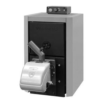
- Page 1 VIADRUS HERCULES Green Eco Therm Manual for boiler operation and installation GB_2015_11...
-
Page 2: Table Of Contents
5.3.5 Mounting of the shells ........................20 5.3.6 Installation of electrical wiring ....................... 21 5.3.6.1 Version VIADRUS HERCULES Green Eco Therm XJ ............21 5.3.6.1 Version VIADRUS HERCULES Green Eco Therm XS ............22 5.3.7 Assembly tools for brush....................... 22 5.3.8... -
Page 3: Produced Variants Of Boiler
Optional accessories (see chapter no. 5.2) The boiler design you received is only destined for wooden pellets combustion (specification see page 4) and its trade name is VIADRUS HERCULES Green Eco Therm. It is the boiler with automatic fuel supply. The burner is cleaned manually. -
Page 4: Technical Data Of The Boiler
Technical data of the boiler Tab. no. 1 Dimensions, thermal parameters of boiler VIADRUS HERCULES VIADRUS HERCULES Green Eco Therm Green Eco Therm Version of boiler Section number Class of boiler according to EN 303-5 Weight including the supplied fuel tank... - Page 5 3000 HERCULES Green Eco Therm 25X 2500 HERCULES Green Eco Therm 32X 2000 1500 1000 Q [dm Version of boiler VIADRUS HERCULES Green Eco Therm 25X VIADRUS HERCULES Green Eco Therm 32X 1335 1527 1001 Fig. no. 1 Boiler dimensions...
-
Page 6: Boiler Description
Boiler description Boiler drum construction The cast iron section boiler drum is the main part of boiler and it is manufactured of grey cast iron according to EN 1561 • central sections – quality 150 (previously ČSN 42 2415) • front and rear sections –... - Page 7 Elements for control, regulation and safety placed on the burner • Control Module of boiler (version VIADRUS HERCULES Green Eco Therm XJ) or automatic (version VIADRUS HERCULES Green Eco Therm XS). • LCD display with control buttons, that is designed for change of the values of operating parameters (version VIADRUS HERCULES Green Eco Therm XJ).
- Page 8 Boiler drum 13. Flange of return water Boiler shell with ashtray 14. Fill and drain cock Cleaning door 15. Sealing 90 x 60 x 3 Burner 16. Assembly of smoke adapter Transitionary flange 17. Turbulators Insulation of burner 18. Partition of flue way The ash door 19.
-
Page 9: The Construction Of Burner And Transport Routes Of The Fuel
The construction of burner and transport routes of the fuel The version VIADRUS HERCULES Green Eco Therm XJ • Control module with microprocessor; • LCD display with control buttons, that is designed for change of the values of operating parameters;... - Page 10 Inlet of electricity Socket for connection of the fuel feeder Fig. no. 5 Basic components of the burner of boiler VIADRUS HERCULES Green Eco Therm XJ Control panel Sensor for penetration of burning fuel (TD)
-
Page 11: Location And Installation
Irreversible thermal label Reversible thermal label with indicator of current temperature of the body of burner Fig. no. 7 Positioning of thermal labels on the burner Location and installation Regulations and directives The solid fuel boiler can only by mounted by a company holding a valid authorization to install these equipments. -
Page 12: Positioning Possibilities
ČSN 33 2000-1 ed. 2 Low-voltage electrical installations – Part Fundamental principles, assessment of general characteristics, definitions. ČSN 33 2000-4-41 ed. 2 Low voltage electrical installations - Part 4- 41: Protection for safety - Protection against electric shock ČSN 33 2000-5-51 ed. 3 Electrical installations of buildings –... - Page 13 Section number L [mm] Fig. no. 8 Bedding dimensions The boiler placing with respect to the necessary handling space: • basic surroundings of AA5/AB5 according to ČSN 33 2000-1 ed. 2; • handling space of minimum 1000 mm in front of the boiler must be maintained; •...
-
Page 14: Order, Delivery And Assembly
Delivery and accessories Boiler VIADRUS HERCULES Green Eco Therm is supplied so that on a pallet there is placed the complete boiler drum and on the side there is attached the wrapped boiler shell. The accessories are stored inside the boiler drum and are accessible after opening the cleaning door. - Page 15 pike 1 pc cleaning equipment holder 1 pcs handling key 1 pc • turbulator 4 pcs • partition of combustion chamber – the front segment 1 pc • the partition of combustion chamber 4 pcs - 7 sect. • the partition of smoke channel 2 pcs •...
-
Page 16: Assembly Procedure
Assembly procedure 5.3.1 Boiler drum installation Position the boiler body on a retaining wall. Put sealing 90 x 60 x 3 (1) onto the upper flange of the rear boiler section and screw the flange of heating water (2) and then interconnect the other end with the heating system. Put sealing 90 x 60 x 3 (5) onto the lower flange of the rear boiler section and screw the flange of heating water with a sleeve (6) for the fill and drain cock and then interconnect the other end with the heating system. -
Page 17: Mounting Of Partitions Of The Combustion Chamber And Turbulators
1.According to Fig no. 12 insert the partitions of the combustion chamber (1, 2) into the combustion chamber in number of 4 pcs (for VIADRUS HERCULES Green Eco Therm 5X) or 5 pcs (for VIADRUS HERCULES Green Eco Therm 7X). - Page 18 Please screw the flange of burner (see Fig. no. 14) onto the ash door by means of 3 pcs screws M10 x 30 (2), 1 pc screw M10 x 50 (2), 4 pcs nuts M10, 4 pcs washers 10,5 and 4 pcs spring washers 10,5.
-
Page 19: Mounting Of The Fuel Reservoir
5.3.4 Mounting of the fuel reservoir ATTENTION! In the event that it is installed the supplied wooden fuel reservoir, it is necessary to place a fireproof bulkhead between it and the boiler. • According to Fig no. 15 you must screw the flange of fuel feeder (3) to the lateral part of the fuel reservoir (6) by using 6 pcs screw M8 x 20 (5), M8 nuts (2) and washers 8.4 (4);... -
Page 20: Mounting Of The Shells
5.3.5 Mounting of the shells Anchor screw 11 Right side part of shell Console 1 12 Screw ST 4,2 x 9,5 Washer 10,5 13 Insulation of the rear part of shell Nut M10 14 Rear part of shell Console 2 15 Upper part of shell Right side part of shell 16 Insulation of the upper part of shell... -
Page 21: Installation Of Electrical Wiring
13. Insert 1 ~ plug of the fuel feeder into the socket of burner. WARNING: Version VIADRUS HERCULES Green Eco Therm XJ is equipped with sensor B1 of hot water. For this reason the operating thermostat in the control box is shunted to... -
Page 22: Version Viadrus Hercules Green Eco Therm Xs
5.3.6.1 Version VIADRUS HERCULES Green Eco Therm XS According to Fig no. 16 equip the upper part of the shell (15) with the glands PG 9 (20) Attach the control box (18) to the upper part of the shell (15) by using of screws M5 x 12 (10) and serrated lock washers 5.3 (19) and pull the capillary tube of safety thermostat, capillary tubes of... -
Page 23: Electrical Scheme
MAIN SWITCH SIGNALLING „SWITCHED ON“ FUSE 10 A SUPPRESSOR FILTER X31.1 10 A THERMOSTAT OF PUMP CENTRAL HEATING PUMP SAFETY THERMOSTAT SIGNALLING OF SAFETY THERMOSTAT *- operational thermostat is put out of its function SWITCH „START OF BURNER“ ROOM THERMOSTAT AUTOMATICS OF BURNER KINDLER OF BURNER FAN OF BURNER... - Page 24 MAIN SWITCH SIGNALLING „SWITCHED ON“ FUSE 10A SUPPRESSOR FILTER X31.1 10A TERMINAL BLOCK SAFETY THERMOSTAT SIGNALLING OF SAFETY THERMOSTAT SWITCH „START OF BURNER“ OPERATIONAL THERMOSTAT THERMOSTAT OF PUMP * - In WL4 cable is alternatively a grey or blue conductor ** - The producer provides two kinds of input cables of the burner, either a tripple-conductor cable WL6 (brown, blue and green-yellow wires) or...
- Page 25 FEEDING MAIN SWITCH SIGNALLING „SWITCHED ON“ FUSE 10 A SUPPRESSOR FILTER X31.1 10 A THERMOSTAT OF PUMP CENTRAL HEATING PUMP SAFETY THERMOSTAT SIGNALLING OF SAFETY THERMOSTAT SWITCH „START OF BURNER“ OPERATIONAL THERMOSTAT ROOM THERMOSTAT AUTOMATICS OF BURNER KINDLER OF BURNER FAN OF BURNER MOTOR OF BURNER FEEDER POTENTIOMETER OF BURNER...
- Page 26 MAIN SWITCH SIGNALLING „SWITCHED ON“ FUSE 10A SUPPRESSOR FILTER X31.1 10A TERMINAL BLOCK SAFETY THERMOSTAT SIGNALLING OF SAFETY THERMOSTAT SWITCH „START OF BURNER“ OPERATIONAL THERMOSTAT THERMOSTAT OF PUMP *- in the cable WL4 alternatively a grey or blue conductor Wire colour GNYE green yellow black...
-
Page 27: Boiler Hydraulic Diagram
5.3.10 Boiler hydraulic diagram Legend of piping, signs and symbols in the diagrams: Fig. no. 19 VIADRUS HERCULES Green Eco Therm boiler hydraulic diagram... -
Page 28: Putting Into Operation - Instructions For Contractual Service Organization
Putting into operation - instructions for contractual service organization The boiler can only be put into operation by a contractual service organization authorized to carry out this activity. Inspections before start-up Before putting the boiler into operation it I necessary to check: Filling the heat system with water (thermomanometer check). -
Page 29: Boiler Operation By User
• pull out the plug from the power supply and insert it back into the socket of burner. Version VIADRUS HERCULES Green Eco Therm XJ Home screen button to enter a submenu or to confirm the setting... - Page 30 The display shows information about the operating mode of the burner - the burner is in the mode of ignition of fuel: IGNITION 1 ON 32 FC: 0% After removal of debris by means of a fan the fuel feeder starts to supply the initial quantity of fuel and the burner performs the ignition of fuel.
-
Page 31: Setting Of The Heat Output Of Burner
Items of user menu of control module of burner The user menu starts up on the display by a long pressing the button "S". By pressing the button "S" you go to the selection of menu of control module of burner. To exit the current item of menu press "ESC". - Page 32 ATTENTION: In case that the fuel has changed (for instance the class of pellets has changed), then an additional adjustment of operating parameters of the burner should be done. NOTE: The burner in case of a change of the degree of heat output automatically re-adjusts the fan power and the quantity of fuel;...
- Page 33 Switching off the burner by means of external control module Turn off the burner by pressing START OF BURNER. Then the control module of burner performs a "controlled shutdown process" during which the fan is kept in operation (burner is cooled down) while simultaneously are monitored the operating parameters.
- Page 34 Tab. no. 4 The error codes, stored in the list "LOG" in the items of menu of burner (25J and 32J). Error Description of fault The way of repair codes Failed ignition Clean the burner grate; Check whether in the fuel feeder and fuel reservoir there is a sufficiency of fuel;...
-
Page 35: Version Viadrus Hercules Green Eco Therm Xs
Version VIADRUS HERCULES Green Eco Therm XS Putting the burner into operation: • The main switch must be in the position on(I) - (green light of main switch on the control box is alight- see Fig. no. 2 and signalling "POWER" on the burner drum - see Figure 20);... - Page 36 Colour scale Lever for setting the position of the throttling flap of the fan Fig. No. 21 The burner is automatically shut down after reaching the desired temperature that is set by the operating thermostat (the fan carries out cleaning of the combustion grate). In case of a request for heating the fan carries out the operations of blowing through, filling fuel and ignition.
-
Page 37: Setting Of The Heat Output Of Burner
Putting the burner out of operation • The burner is put out of operation by pressing "START OF BURNER" button (signalling of "START" on the body of the burner is off). The burner during becoming extinct performs so called "process of controlled switching off"... - Page 38 6,22 7,46 8,21 450* factory setting Tab. no. 8 Setting of burner output by means of potentiometer Heat output of boiler [kW] VIADRUS HERCULES Green Eco Therm (number of flickers of yellow LED) 11,0 11,0 14,0 14,0 18,0 18,0 21,0...
- Page 39 Example of calculating the heat output of the burner: • Determine the amount of fuel supplied per hour - m = 5.3 kg / hr. fuel Calculate the instantaneous amount of supplied fuel m' fuel (kg/h) fuel 0,001472 kg/s fuel 3600 (s) •...
-
Page 40: Important Warnings
IMPORTANT WARNINGS The boiler must not be used for other purposes than those it is designed for. The boiler can only be operated by adults who are acquainted with this operation manual. It is forbidden to leave children unattended near the boiler that is working. The boiler is not destined for use by persons (including children) whose physical, sensual or mental inability or lack of experience and knowledge prevents from a safe use of the appliance in case they are not under supervision or are not instructed regarding the use of the appliance by a... -
Page 41: Maintenance
Maintenance Regularly remove ashes from the combustion chamber and the ash drawer. The ashes must be thrown out into non-combustible containers with lids. When working is necessary to use protective equipment and respect the personal safety. The boiler has to be put out of operation at least 1 hour before cleaning (incl. the electric disconnection). - Page 42 The body of burner Inclined grate of combustion chamber 1. Initial position of the grate 2. End position of the grate Small feet of the grate Fig. no. 23 Fig. no. 24 End position of the grate...
-
Page 43: Faults And Their Removal
The burner does not start and the signal Check whether burner is not in a fault status - see is alight Tab. no. 4 and 5 (VIADRUS HERCULES Green Eco Therm XJ) and 9 (VIADRUS HERCULES Green Eco Therm XS) - Page 44 The operating parameters of the control Check the position of the potentiometer of heat module were changed output (VIADRUS HERCULES Green Eco Therm Check the degree of operational heat output of the control module of burner (VIADRUS HERCULES Green Eco Therm XJ);...
-
Page 45: Instructions For Product Liquidation After Its Operating Life
The user is obliged to leave the boiler installation to an assembly company, putting into operation and defect removing only to a professional contractual service accredited by the boiler producer VIADRUS a.s. otherwise the warranty for proper boiler operation is not valid. - Page 46 Information for customer Packaging edentification Assessment reference PE Plastic sacks, folie, corrugaled board, iron and plastic fix line Identification od principál materials used. Paper, Polyethylene, iron, wood Part 1: Summary of assessment Standard/Report Assessment requirement Claim Note 1.1 Prevention by source reduction 1.2 Heavy metals and ensure below maximum permitted levels...
- Page 47 Annex to the guarantee certificate for the customer-user Record of the carried out guarantee and after-guarantee repairs and regular product inspections Contractual service Date of Customer’s Carried out activity organization record signature (signature, stamp)
- Page 48 VIADRUS HERCULES Green Eco Therm VIADRUS a.s. Bezručova 300 | CZ - 735 81 | Bohumín E-mail : info@viadrus.cz | www.viadrus.cz...
Need help?
Do you have a question about the HERCULES Green Eco Therm Series and is the answer not in the manual?
Questions and answers