Advertisement
Quick Links
GIGABIT
PoE
SWITCH
Q
I
uick
nstallation
M A N A G E D
Rack-Mount
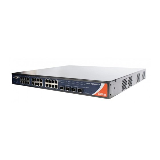
Introduction
The
RGPS-R9244GP+ series
are Layer-3 Gigabit managed Ethernet
switches with 24x 10/100/1000Base-T(X) IEEE802.3at P.S.E. ports and
4x1G/10GBase-X SFP+ ports. Consisting of the
RGPS-R9244GP+-P
, and
RGPS-R9244GP+-LP
supply options, these models are able to meet the needs for high port
density and high-speed, long-distance transmission. The P.S.E-enabled
ports are able to provide sufficient power for power-hungry devices with up
to 30W per port. With complete support for Ethernet redundancy protocols
such as O-Ring (recovery time < 30ms) and MSTP (RSTP/STP compatible),
the switch can protect your mission-critical applications from network
interruptions or temporary malfunctions with its fast recovery technology.
Featuring a wide operating temperature from -20 C to 60 C, the device can
be managed centrally and conveniently via Open-Vision, web browsers,
Telnet and console (CLI) configuration, making it one of the most reliable
choice for highly-managed and Fiber Ethernet power substation and rolling
stock application.
Package Contents
Contents
Pictures
Number
RGPS-R9244GP+ or
X 1
RGPS-R9244GP+-P or
RGPS-R9244GP+-LP
X 1
Console Cable
X 1
CD
X 1
QIG
Screw (M4 X6)
X 6
Rack-mounted
X 1
kit (L&R)
X 1
Power cord
Preparation
Before you begin installing the switch, make sure you have all of the package
contents available and a PC with Microsoft Internet Explorer 6.0 or later, for
using web-based system management tools.
Safety & Warnings
Elevated Operating Ambient: If installed in a closed or multi-unit rack
assembly, the operating ambient temperature of the rack environment may be
greater than room ambient. Therefore, consideration should be given to
installing the equipment in an environment compatible with the maximum
ambient temperature (Tma) specified by the manufacturer.
Q I G
RGPS-R9244GP+ Series
RGPS-R9244GP+ Series
G
uide
Reduced Air Flow: Installation of the equipment in a rack should be such that the
amount of air flow required for safe operation of the equipment is not
compromised.
RGPS-R9244GP+
,
featuring different power
Mechanical Loading: Mounting of the equipment in the rack should be such that a
hazardous condition is not achieved due to uneven mechanical loading.
Circuit Overloading: Consideration should be given to the connection of the equipment
to the supply circuit and the effect that overloading of the circuits might have on
overcurrent protection and supply wiring. Appropriate consideration of equipment
nameplate ratings should be used when addressing this concern.
Dimension
o
o
49.0
17.80
30.20
G2
G4
G6
G8
G10
G12
G14
G16
Console
Fault
Reset
R.M.
PWR
Ring
G1
G3
G5
G7
G9
G11
G13
G15
Panel Layouts
Front View
1
8 9
G2
G4
G6
G8
G10
G12
G14
Console
Fault
R.M.
Reset
PWR
Ring
G1
G3
G5
G7
G9
G11
G13
2 3 4 5 6
7
1. Console port
2. Reset button
3. Power indicator
4. Ring status LED
5. R.M. status LED
6. Fault indicator
RGPS-R9244GP+
RGPS-R9244GP+-P/ -LP
1907-2-29-RGPSR9244GP+-1.0
25.50
35.50
8.00
20.00
431.00
5.50
G18
G20
G22
G24
10/100/
G2
G8
G10
G16
G18
G24
RGPS-R9244GP+
1000T
G1
G7
G9
G15
G17
G23
PoE
LINK/ACT
10G SFP+
G17
G19
G21
G23
G25
G26
G27
G28
R3.25
12
G16
G18
G20
G22
G24
10/100/
G2
G8
G10
G16
G18
G24
RGPS-R9244GP+
PoE
1000T
G1
G7
G9
G15
G17
G23
LINK/ACT
10G SFP+
G15
G17
G19
G21
G23
G25
G26
G27
G28
10
11
7. LAN ports
8. LNK/ACT LED for even Ethernet ports
9. LNK/ACT LED for odd Ethernet ports
10. SFP+ ports
11. LNK/ACT LED for SFP+ ports
12. PoE status LED for LAN ports
Rear View
V+
V +
V+
V-
V-
DC Power 50V
1. Ground screw
2. Terminal block with DC power inputs
1
2
3. AC power supply (100V~240V
/ 50~60Hz)
AC 100-240V 50-60Hz
1
3
PRINTED ON RECYCLED PAPER
Layer-3 Managed Gigabit PoE
Ethernet Switch
Installation
Rack-mounting
Step 1: Install left and right front mounting brackets to the switch using three screws on each side.
Step 2: With front brackets orientated in front of the rack, fasten the brackets to the rack using two
more screws.
Network Connection
The series have standard Ethernet ports. According to the link type, the switch uses CAT 3, 4,
5,5e UTP cables to connect to any other network devices (PCs, servers, switches, routers, or
hubs). Please refer to the following table for cable specifications.
Cable Types and Specifications:
Cable
Type
Max. Length
Connector
10BASE-T
Cat. 3, 4, 5 100-ohm
UTP 100 m (328 ft)
RJ-45
100BASE-TX
Cat. 5 100-ohm UTP
UTP 100 m (328 ft)
RJ-45
1000BASE-T
Cat. 5 / Cat. 5e 100-ohm UTP
UTP 100 m (328 ft)
RJ-45
With 10/100BASE-T(X) cables, pins 1 and 2 are used for transmitting data, and pins 3 and 6 are
used for receiving data. The device also supports auto MDI/MDI-X operation. You can use a cable
to connect the switch to a PC.
For pin assignments for different types of cables, please refer to the following tables.
10/100Base-T(X) P.S.E. RJ-45 port
1000Base-T P.S.E. RJ-45 port
Pin Number
Assignment
Pin Number
#1
TD+ with PoE Power input +
#1
BI_DA+ with PoE Power input +
#2
TD- with PoE Power input +
#2
BI_DA- with PoE Power input +
#3
RD+ with PoE Power input -
#3
BI_DB+ with PoE Power input -
#6
RD- with PoE Power input -
#4
#5
#6
BI_DB- with PoE Power input -
#7
#8
Quick Installation Guide
Version 1.0
Assignment
BI_DC+
BI_DC-
BI_DD+
BI_DD-
Advertisement

Related Manuals for ORiNG RGPS-R9244GP+ Series


Summary of Contents for ORiNG RGPS-R9244GP+ Series
- Page 1 Version 1.0 GIGABIT Layer-3 Managed Gigabit PoE RGPS-R9244GP+ Series SWITCH Ethernet Switch uick nstallation uide M A N A G E D Rack-Mount Introduction Installation Rack-mounting RGPS-R9244GP+ series are Layer-3 Gigabit managed Ethernet Reduced Air Flow: Installation of the equipment in a rack should be such that the switches with 24x 10/100/1000Base-T(X) IEEE802.3at P.S.E.
- Page 2 RS-232 Serial Console Port RS-232 in DB-9 connector with console cable. 115200bps, 8, N, 1 AC Power Connection For information on operating the switch using ORing’s Open-Vision management utility, please go Fault Contact to ORing website. Both RGPS-R9244GP+-P and RGPS-R9244GP+-LP come with an AC...
Need help?
Do you have a question about the RGPS-R9244GP+ Series and is the answer not in the manual?
Questions and answers