Table of Contents
Advertisement
Quick Links
Advertisement
Table of Contents

Related Manuals for Supermicro 5018D2-AR12L


Summary of Contents for Supermicro 5018D2-AR12L
- Page 1 UPER TORAGE YSTEM 5018D2-AR12L 5018D4-AR12L 5018D8-AR12L USER’S MANUAL 1.0b...
- Page 2 This product, including software and docu- mentation, is the property of Supermicro and/or its licensors, and is supplied only under a license. Any use or reproduction of this product is not allowed, except as expressly permitted by the terms of said license.
- Page 3 DV-4C-7TP4F/X10SDV-7TP4F motherboard and the SC801LTS-R406P chassis. Chapter 2: Server Installation This chapter describes the steps necessary to install the SuperStorage Server 5018D2-AR12L/5018D4-AR12L/5018D8-AR12L into a rack and check out the server configuration prior to powering up the system. Chapter 3: Standardized Warning Statements...
- Page 4 UPER TORAGE YSTEM 5018D2-AR12L/D4-AR12L/D8-AR12L User's Manual Chapter 6: Advanced Chassis Setup Refer to Chapter 6 for detailed information on the SC801LTS-R406P server chassis. You should follow the procedures given in this chapter when installing, removing or reconfiguring SATA drives and when replacing system power supply units and cooling fans.
- Page 5 Preface Notes...
-
Page 6: Table Of Contents
UPER TORAGE YSTEM 5018D2-AR12L/D4-AR12L/D8-AR12L User's Manual Table of Contents Chapter 1 Introduction Overview ......................1-1 Motherboard Features ..................1-2 Processors ...................... 1-2 Memory ......................1-2 SAS/SATA......................1-2 PCI Expansion Slots ..................1-2 Rear I/O Ports ....................1-2 Graphics Controller ..................1-2 Server Chassis Features ................ - Page 7 Table of Contents Power ......................3-2 Reset ....................... 3-2 Control Panel LEDs ..................3-2 UID LED ......................3-2 NIC ........................3-2 HDD ......................... 3-3 Power Supply LEDs ..................3-3 Chapter 4 Standardized Warning Statements for AC Systems About Standardized Warning Statements ............4-1 Warning Definition ...................
- Page 8 UPER TORAGE YSTEM 5018D2-AR12L/D4-AR12L/D8-AR12L User's Manual SuperDoctor® 5 .................... 5-23 5-13 Onboard Battery .................... 5-24 Chapter 6 Advanced Chassis Setup Static-Sensitive Devices .................. 6-1 Precautions ..................... 6-1 Unpacking ....................... 6-1 Control Panel ....................6-2 Removing Power from the System ..............6-2 Removing the Chassis Cover .................
-
Page 9: Chapter 1 Introduction
X10SDV-2C-7TP4F/X10SDV-4C-7TP4F/X10SDV-7TP4F single processor motherboard. Please refer to our website for information on operating systems that have been certified for use with the system (www.supermicro.com). In addition to the motherboard and chassis, various hardware components have been included with the 5018D2-AR12L/5018D4-AR12L/5018D8-AR12L, as listed below: •... -
Page 10: Motherboard Features
UPER TORAGE YSTEM 5018D2-AR12L/D4-AR12L/D8-AR12L User's Manual Motherboard Features The SuperStorage Server 5018D2-AR12L/5018D4-AR12L/5018D8-AR12L is built around the X10SDV-2C-7TP4F/X10SDV-4C-7TP4F/X10SDV-7TP4F, a single processor motherboard. Below are the main features of the X10SDV-2C-7TP4F/ X10SDV-4C-7TP4F/X10SDV-7TP4F. See Section 5-6 for a layout and cariances of the three motherboards. -
Page 11: Server Chassis Features
Chapter 1: Introduction Server Chassis Features The SC801LTS-R406P is a proprietaty form factor chassis designed to be used in a 1U rackmount configuration. The following is a general outline of the main features of the SC801LTS-R406P server chassis. System Power The chassis features a redundant 400W power supply consisting of two separate power supply modules. - Page 12 UPER TORAGE YSTEM 5018D2-AR12L/D4-AR12L/D8-AR12L User's Manual Figure 1-1. X10SDV Flex ATX Series: System Block Diagram Note: This is a general block diagram. Please see Chapter 5 for details. DDR4 1600/1866/2133 PCIE 3.0 x8 JPCIE1 PCIE 3.0 x8 PCIE 3.0 x8 JPCIE2 PCIE 3.0 x8...
-
Page 13: Contacting Supermicro
Super Micro Computer, Inc. 980 Rock Ave. San Jose, CA 95131 U.S.A. Tel: +1 (408) 503-8000 Fax: +1 (408) 503-8008 Email: marketing@supermicro.com (General Information) support@supermicro.com (Technical Support) Web Site: www.supermicro.com Europe Address: Super Micro Computer B.V. Het Sterrenbeeld 28, 5215 ML... - Page 14 UPER TORAGE YSTEM 5018D2-AR12L/D4-AR12L/D8-AR12L User's Manual Notes...
-
Page 15: Chapter 2 Server Installation
Preparing for Setup The box the 5018D2-AR12L/5018D4-AR12L/5018D8-AR12L was shipped in should include two sets of rail assemblies, two rail mounting brackets and the mounting screws you will need to install the system into the rack. Follow the steps in the order given to complete the installation process in a minimum amount of time. -
Page 16: Warnings And Precautions
UPER TORAGE YSTEM 5018D2-AR12L/D4-AR12L/D8-AR12L User's Manual • This product is not suitable for use with visual display work place devices acccording to §2 of the the German Ordinance for Work with Visual Display Units. Warnings and Precautions Rack Precautions •... -
Page 17: Rack Mounting Considerations
Chapter 2: Server Installation Rack Mounting Considerations Ambient Operating Temperature If installed in a closed or multi-unit rack assembly, the ambient operating tempera- ture of the rack environment may be greater than the ambient temperature of the room. Therefore, consideration should be given to installing the equipment in an environment compatible with the manufacturer’s maximum rated ambient tempera- ture (Tmra). -
Page 18: Installing The System Into A Rack
UPER TORAGE YSTEM 5018D2-AR12L/D4-AR12L/D8-AR12L User's Manual Installing the System into a Rack This section provides information on installing the chassis into a rack unit with the rails provided. There are a variety of rack units on the market, which may mean the assembly procedure will differ slightly. -
Page 19: Assembling The Outer Rails
Chapter 2: Server Installation Assembling the Outer Rails Each outer rail comes in two sections that must be assembled before mounting onto the rack. Assembling the Outer Rails 1. Identify the left and right outer rails by examining the ends, which bend out- ward. -
Page 20: Installing The Outer Rails Onto The Rack
UPER TORAGE YSTEM 5018D2-AR12L/D4-AR12L/D8-AR12L User's Manual Installing the Outer Rails onto the Rack Each end of the assembled outer rail includes a bracket with square pegs to fit into your rack holes. If you have an older rack with round holes, these brackets must be removed, and you must use screws to secure the rail to the rack. -
Page 21: Sliding The Chassis Onto The Rack
Chapter 2: Server Installation Sliding the Chassis onto the Rack Installing the Chassis into a Rack 1. Align the chassis rails with the front of the rack rails. 2. Slide the chassis rails into the rack rails, keeping the pressure even on both sides. - Page 22 UPER TORAGE YSTEM 5018D2-AR12L/D4-AR12L/D8-AR12L User's Manual Notes...
-
Page 23: Chapter 3 System Interface
Chapter 3: System Interface Chapter 3 System Interface Overview The control panel includes LEDs keep you constantly informed of the overall status of the system. There are also two buttons on the chassis control panel. Figure 3-1. Control Panel... -
Page 24: Control Panel Buttons
UPER TORAGE YSTEM 5018D2-AR12L/D4-AR12L/D8-AR12L User's Manual Control Panel Buttons There are two buttons located on the front of the chassis: a reset button and a power on/off button. Power The main power switch is used to apply or remove power from the power supply to the server. -
Page 25: Hdd
Chapter 3: System Interface When flashing, this LED indicates activity on the hard drives controlled by the on- chip SATA controller. Power Supply LEDs An LED on the rear of the power supply module displays the power status. • Solid Green: When illuminated, indicates that the power supply is on. •... - Page 26 UPER TORAGE YSTEM 5018D2-AR12L/D4-AR12L/D8-AR12L User's Manual Notes...
-
Page 27: Chapter 4 Standardized Warning Statements For Ac Systems
The following statements are industry standard warnings, provided to warn the user of situations which have the potential for bodily injury. Should you have questions or experience difficulty, contact Supermicro's Technical Support department for assistance. Only certified technicians should attempt to install or configure components. - Page 28 UPER TORAGE YSTEM 5018D2-AR12L/D4-AR12L/D8-AR12L User's Manual Warnung WICHTIGE SICHERHEITSHINWEISE Dieses Warnsymbol bedeutet Gefahr. Sie befinden sich in einer Situation, die zu Verletzungen führen kann. Machen Sie sich vor der Arbeit mit Geräten mit den Gefahren elektrischer Schaltungen und den üblichen Verfahren zur Vorbeugung vor Unfällen vertraut.
- Page 29 Warning Statements for AC Systems جسذٌة اصابة ًتتسبب ف حالة ٌوكي أى ًاًك ف خطز ًٌٌع هذا الزهز !تحذٌز الذوائز بالوخاطز الٌاجوة عي ي على علن ، ك هعذات تعول على أي قبل أى الكهزبائٍة حىادث أي وقىع وٌع ل الىقائٍة...
-
Page 30: Installation Instructions
UPER TORAGE YSTEM 5018D2-AR12L/D4-AR12L/D8-AR12L User's Manual Installation Instructions Warning! Read the installation instructions before connecting the system to the power source. 設置手順書 システムを電源に接続する前に、 設置手順書をお読み下さい。 警告 将此系统连接电源前,请先阅读安装说明。 警告 將系統與電源連接前,請先閱讀安裝說明。 Warnung Vor dem Anschließen des Systems an die Stromquelle die Installationsanweisungen lesen. -
Page 31: Circuit Breaker
Chapter 4: Warning Statements for AC Systems Circuit Breaker Warning! This product relies on the building's installation for short-circuit (overcurrent) protection. Ensure that the protective device is rated not greater than: 250 V, 20 A. サーキッ ト ・ ブレーカー この製品は、 短絡 (過電流) 保護装置がある建物での設置を前提としています。 保護装置の定格が250 V、... -
Page 32: Power Disconnection Warning
UPER TORAGE YSTEM 5018D2-AR12L/D4-AR12L/D8-AR12L User's Manual 경고! 이 제품은 전원의 단락(과전류)방지에 대해서 전적으로 건물의 관련 설비에 의존합니다. 보호장치의 정격이 반드시 250V(볼트), 20A(암페어)를 초과하지 않도록 해야 합니다. Waarschuwing Dit product is afhankelijk van de kortsluitbeveiliging (overspanning) van uw electrische installatie. Controleer of het beveiligde aparaat niet groter gedimensioneerd is dan 220V, 20A. - Page 33 Chapter 4: Warning Statements for AC Systems ¡Advertencia! El sistema debe ser disconnected de todas las fuentes de energía y del cable eléctrico quitado de los módulos de fuente de alimentación antes de tener acceso el interior del chasis para instalar o para quitar componentes de sistema. Attention Le système doit être débranché...
-
Page 34: Equipment Installation
UPER TORAGE YSTEM 5018D2-AR12L/D4-AR12L/D8-AR12L User's Manual Equipment Installation Warning! Only trained and qualified personnel should be allowed to install, replace, or service this equipment. 機器の設置 トレーニングを受け認定された人だけがこの装置の設置、 交換、 またはサービスを許可 されています。 警告 只有经过培训且具有资格的人员才能进行此设备的安装、更换和维修。 警告 只有經過受訓且具資格人員才可安裝、更換與維修此設備。 Warnung Das Installieren, Ersetzen oder Bedienen dieser Ausrüstung sollte nur geschultem, qualifiziertem Personal gestattet werden. -
Page 35: Restricted Area
Chapter 4: Warning Statements for AC Systems Waarschuwing Deze apparatuur mag alleen worden geïnstalleerd, vervangen of hersteld door geschoold en gekwalificeerd personeel. Restricted Area Warning! This unit is intended for installation in restricted access areas. A restricted access area can be accessed only through the use of a special tool, lock and key, or other means of security. -
Page 36: Battery Handling
UPER TORAGE YSTEM 5018D2-AR12L/D4-AR12L/D8-AR12L User's Manual אזור עם גישה מוגבלת !אזהרה יש להתקין את היחידה באזורים שיש בהם הגבלת גישה. הגישה ניתנת בעזרת .)'כלי אבטחה בלבד (מפתח, מנעול וכד محظورة مناطق ٍنتركُبها ف هذه انىحذة تخصيص تم ،أداة خاصت من خالل استخذاو... - Page 37 Chapter 4: Warning Statements for AC Systems Warnung Bei Einsetzen einer falschen Batterie besteht Explosionsgefahr. Ersetzen Sie die Batterie nur durch den gleichen oder vom Hersteller empfohlenen Batterietyp. Entsorgen Sie die benutzten Batterien nach den Anweisungen des Herstellers. Attention Danger d'explosion si la pile n'est pas remplacée correctement. Ne la remplacer que par une pile de type semblable ou équivalent, recommandée par le fabricant.
-
Page 38: Redundant Power Supplies
UPER TORAGE YSTEM 5018D2-AR12L/D4-AR12L/D8-AR12L User's Manual Redundant Power Supplies Warning! This unit might have more than one power supply connection. All connections must be removed to de-energize the unit. 冗長電源装置 このユニッ トは複数の電源装置が接続されている場合があります。 ユニッ トの電源を切るためには、 すべての接続を取り外さなければなりません。 警告 此部件连接的电源可能不止一个,必须将所有电源断开才能停止给该部件供电。 警告 此裝置連接的電源可能不只一個,必須切斷所有電源才能停止對該裝置的供電。 Warnung Dieses Gerät kann mehr als eine Stromzufuhr haben. -
Page 39: Backplane Voltage
Chapter 4: Warning Statements for AC Systems امداد الطاقة بوحدات عدة اتصاالت جهاز ال يكون لهذا قد الكهرباء عن وحدة ال لعسل كافة االتصاالت يجب إزالة 경고! 이 장치에는 한 개 이상의 전원 공급 단자가 연결되어 있을 수 있습니다. 이 장치에 전원을... -
Page 40: Comply With Local And National Electrical Codes
UPER TORAGE YSTEM 5018D2-AR12L/D4-AR12L/D8-AR12L User's Manual מתח בפנל האחורי !הרה אז קיימת סכנת מתח בפנל האחורי בזמן תפעול המערכת. יש להיזהר במהלך .העבודה اللىحة أوالطاقة المىجىدة على التيار الكهزبائي مه خطز هناك هذا الجهاس خدمة كه حذرا عند يعمل النظام... -
Page 41: Product Disposal
Chapter 4: Warning Statements for AC Systems Attention L'équipement doit être installé conformément aux normes électriques nationales et locales. תיאום חוקי החשמל הארצי !אזהרה הציוד חייבת להיות תואמת לחוקי החשמל המקומיים והארציים התקנת المتعلقة المحلية والىطىية قىاويه يجب أن يمتثل لل الكهربائية... -
Page 42: Hot Swap Fan Warning
UPER TORAGE YSTEM 5018D2-AR12L/D4-AR12L/D8-AR12L User's Manual ¡Advertencia! Al deshacerse por completo de este producto debe seguir todas las leyes y reglamentos nacionales. Attention La mise au rebut ou le recyclage de ce produit sont généralement soumis à des lois et/ou directives de respect de l'environnement. Renseignez-vous auprès de l'organisme compétent. - Page 43 Chapter 4: Warning Statements for AC Systems 警告 當您從機架移除風扇裝置,風扇可能仍在轉動。小心不要將手指、螺絲起子和其他 物品太靠近風扇。 Warnung Die Lüfter drehen sich u. U. noch, wenn die Lüfterbaugruppe aus dem Chassis genommen wird. Halten Sie Finger, Schraubendreher und andere Gegenstände von den Öffnungen des Lüftergehäuses entfernt. ¡Advertencia! Los ventiladores podran dar vuelta cuando usted quite ell montaje del ventilador del chasis.
-
Page 44: Power Cable And Ac Adapter
Electrical Appliance and Material Safety Law prohibits the use of UL or CSA -certified cables (that have UL/CSA shown on the code) for any other electrical devices than products designated by Supermicro only. 電源コードとACアダプター 製品を設置する場合、 提供または指定された接続ケーブル、 電源コードとACアダプター... - Page 45 Appareils électroménagers et de loi sur la sécurité Matériel interdit l'utilisation de UL ou CSA câbles certifiés qui ont UL ou CSA indiqué sur le code pour tous les autres appareils électriques que les produits désignés par Supermicro seulement.
- Page 46 UPER TORAGE YSTEM 5018D2-AR12L/D4-AR12L/D8-AR12L User's Manual Notes 4-20...
-
Page 47: Chapter 5 Advanced Motherboard Setup
Chapter 5: Advanced Motherboard Setup Chapter 5 Advanced Motherboard Setup This chapter describes the X10SDV-2C-7TP4F/X10SDV-4C-7TP4F/X10SDV- 7TP4F motherboard including how to connect the data and power cables and install add-on cards. All motherboard jumpers and connections are described and a layout and quick reference chart are included in this chapter. Remember to close the chassis completely when you have finished working on the motherboard to protect and cool the system sufficiently. -
Page 48: Connecting Cables
UPER TORAGE YSTEM 5018D2-AR12L/D4-AR12L/D8-AR12L User's Manual Connecting Cables The cables include the data cables for the peripherals and control panel and the power cables. Connecting Data Cables The cables used to transfer data from the peripheral devices have been carefully routed in preconfigured systems to prevent them from blocking the flow of cooling air that moves through the system from front to back. -
Page 49: I/O Ports
Chapter 5: Advanced Motherboard Setup Figure 5-1. Front Control Panel Header Pins (JF1) FP PWR LED 3.3 V 3.3V Stby HDD LED 3.3V Stby NIC1 Activity LED 3.3V Stby NIC2 Activity LED UID LED OH/Fan Fail/PWR Fail 3.3V Power Fail LED Reset Reset Button Ground... -
Page 50: Installing Memory
UPER TORAGE YSTEM 5018D2-AR12L/D4-AR12L/D8-AR12L User's Manual Installing Memory Note: Check the Supermicro website for recommended memory modules. CAUTION Exercise extreme care when installing or removing DIMM modules to prevent any possible damage. Installing DIMMs 1. Insert the desired number of DIMMs into the memory slots, starting with slots DIMMA1. -
Page 51: Adding Pci Expansion Cards
Chapter 5: Advanced Motherboard Setup Recommended Population (Balanced) DIMMA1 Slot DIMMB1 Slot DIMMA2 Slot DIMMB2 Slot Total System Memory 16GB 16GB 32GB 16GB 16GB 32GB 16GB 16GB 16GB 16GB 64GB 32GB 32GB 64GB 32GB 32GB 32GB 32GB 128GB Adding PCI Expansion Cards PCI Expansion Slots One RSC-RR1U-E8 riser card is used to support a FHHL (full-height, half-length) expansion (add-on) card to the system. -
Page 52: Motherboard Details
UPER TORAGE YSTEM 5018D2-AR12L/D4-AR12L/D8-AR12L User's Manual Motherboard Details Figure 5-4. SUPER X10SDV Series Layout LAN7/8 JPL3 LAN5/6 LED8 IPMI LAN LAN3/4 LEDM1 LED7 USB0/1 MP-SRW1 LAN1/2 MP-SRW2 JI2C1/JI2C2: JBR1 LED7 1-2:ENABLE 1-2:NORMAL PRESS FIT BAR CODE 2-3:DISABLE 2-3:BIOS RECOVERY JPG1:... -
Page 53: X10Sdv Series Quick Reference
Chapter 5: Advanced Motherboard Setup X10SDV Series Quick Reference Jumper Description Default Setting JBR1 BIOS Recovery Pins 1-2 (Normal) JBT1 CMOS Clear See Section 5-8 C1/JI SMB to PCI-Exp. Slots /Disable Pins 2-3 (Disabled) JPB1 BMC Enable/Disable (Debug use only) Pins 1-2 (Enabled) JPG1 VGA Enable/Disable... - Page 54 UPER TORAGE YSTEM 5018D2-AR12L/D4-AR12L/D8-AR12L User's Manual Connector Description JOH1 Overheat LED Header JPH1 4-pin Power Connector for HDDs Power Supply SMBus I C Header JPV1 12V 8-pin Power Connector (provides alternate power for special enclosure when the 24-pin ATX power is not in use)
-
Page 55: Connector Definitions
Chapter 5: Advanced Motherboard Setup Connector Definitions ATX Power 24-pin Connector Pin Definitions (JPW1) Pin# Definition Pin # Definition +3.3V +3.3V -12V +3.3V Power Connectors The 24-pin ATX power connector at PS_ON JPW1 is used to provide power to the motherboard. JPV1 is a 12V DC power connector that provides alter- native power for special a enclosure Res (NC) - Page 56 UPER TORAGE YSTEM 5018D2-AR12L/D4-AR12L/D8-AR12L User's Manual NIC1/NIC2 (LAN1/LAN2) LAN1/LAN2 LED Pin Definitions (JF1) The NIC (Network Interface Control- Pin# Definition ler) LED connection for LAN port 2 9-11 3.3V Standby is located on pins 9 and 10 of JF1, 10-12...
- Page 57 Chapter 5: Advanced Motherboard Setup Power Button The Power Button connection is lo- cated on pins 1 and 2 of JF1. Momen- Power Button Pin Definitions (JF1) tarily contacting both pins will power Pin# Definition on/off the system. This button can be configured as 4 Seconds Override or Signal Instant Off (with a setting in the BIOS...
- Page 58 UPER TORAGE YSTEM 5018D2-AR12L/D4-AR12L/D8-AR12L User's Manual Unit Identifier Switch UID Switch A Unit Identifier (UID) switch and two LED in- Pin# Definition dicators are located on the motherboard. The Ground UID switch is located next to the VGA port on Ground the back panel.
- Page 59 LAD0 Note: Please go to the following link for SMB_CLK4 SMB_DAT4 more information on TPM: http://www. +3V_DUAL SERIRQ supermicro.com/manuals/other/TPM.pdf CLKRUN# (X) LPCPD# LDRQ# (X) External I C Header Pin Definitions 4-pin External I C BMC Header...
- Page 60 Refer to the table on the right for pin definitions. No connection NVMe I C Header Connector JNVI C is a management header for the Supermicro AOC NVMe PCI-E peripheral cards. Please connect the I C cable to this connector. 5-14...
- Page 61 Chapter 5: Advanced Motherboard Setup GPIO Header Pin Definitions Pin# Definition Definition General Purpose I/O Header P3V3 JGP1 is a general purpose I/O header. See the table on the right for pin defini- tions. GPIO Register Address Table To Control JGPIO Pin Header JGPIO1 PIN# SoC GPIO# USE Select...
-
Page 62: Jumper Settings
UPER TORAGE YSTEM 5018D2-AR12L/D4-AR12L/D8-AR12L User's Manual Jumper Settings Explanation of Jumpers To modify the operation of the mother- board, jumpers can be used to choose Connector between optional settings. Jumpers cre- Pins ate shorts between two pins to change the function of the connector. Pin 1 is... - Page 63 Chapter 5: Advanced Motherboard Setup PCI-E Slot SMB Enable (I C1/I PCI Slot SMB Enable Use jumpers I C1/I C2 to enable PCI Jumper Settings SMB (System Management Bus) support Pin# Definition to improve system management for the Pins 1-2 Enabled onboard PCI-E slot.
- Page 64 UPER TORAGE YSTEM 5018D2-AR12L/D4-AR12L/D8-AR12L User's Manual BIOS Recovery BIOS Recovery Close pins 2 and 3 of jumper JBR1 for Jumper Settings BIOS recovery. The default setting is on Pin# Definition pins 1 and 2 for normal operation. See Pins 1-2 Normal the table on the right for jumper settings.
-
Page 65: Onboard Indicators
Chapter 5: Advanced Motherboard Setup ME Manufacturing Mode Close JPME2 to bypass SPI flash se- Manufacturing Mode curity and force the system to use the Jumper Settings Manufacturing Mode, which will allow Pin# Definition the user to flash the system firmware Pins 1-2 Normal (Default) from a host server to modify system... - Page 66 UPER TORAGE YSTEM 5018D2-AR12L/D4-AR12L/D8-AR12L User's Manual Unit Identification LED A rear UID LED indicator (LED7) is located next to the Unit Identifier (UID) switch on the I/O back panel. The front panel UID LED is located at pin 7 of the Front Control Panel at JF1.
-
Page 67: 5-10 Sata/Sas Ports
SATA Ports This motherboard has six SATA 3.0 ports. I-SATA0 and I-SATA1 have built-in power pins to support Supermicro's SATA DOM (Disk On Module) solutions. I-SATA4 is via the JMD1 M.2 connector, I-SATA5 is via the JMP1 Mini PCI-E slot. -
Page 68: 5-11 Installing Drivers
TORAGE YSTEM 5018D2-AR12L/D4-AR12L/D8-AR12L User's Manual 5-11 Installing Drivers The Supermicro FTP site contains drivers and utilities for your system at ftp://ftp. supermicro.com. Some of these must be installed, such as the chipset driver. After accessing the FTP site, go into the CDR_Images directory and locate the ISO file for your motherboard. -
Page 69: Superdoctor® 5
Chapter 5: Advanced Motherboard Setup SuperDoctor® 5 The Supermicro SuperDoctor 5 is a program that functions in a command-line or web-based interface in Windows and Linux operating systems. The program moni- tors system health information such as CPU temperature, system voltages, system power consumption, fan speed, and provides alerts via email or Simple Network Management Protocol (SNMP). -
Page 70: 5-13 Onboard Battery
UPER TORAGE YSTEM 5018D2-AR12L/D4-AR12L/D8-AR12L User's Manual 5-13 Onboard Battery Care must be taken to assure that the chassis cover is in place when the system is operating to assure proper cooling. Out of warranty damage to the system can occur if this practice is not strictly followed. -
Page 71: Chapter 6 Advanced Chassis Setup
Chapter 6: Advanced Chassis Setup Chapter 6 Advanced Chassis Setup This chapter covers the steps required to install components and perform main- tenance on the SC801LTS-R406P chassis. For component installation, follow the steps in the order given to eliminate the most common problems encountered. If some steps are unnecessary, skip ahead to the step that follows. -
Page 72: Control Panel
UPER TORAGE YSTEM 5018D2-AR12L/D4-AR12L/D8-AR12L User's Manual Figure 6-1. Front and Rear Chassis Views Control Panel Power Supplies I/O Ports Control Panel The control panel (located on the front of the chassis) must be connected to the JF1 connector on the motherboard to provide you with system status indications. A ribbon cable has bundled these wires together to simplify the connection. -
Page 73: Removing The Chassis Cover
Chapter 6: Advanced Chassis Setup Removing the Chassis Cover The system is fully accessible by removing the two chassis covers. Each is secured by a small metal lip in the middle of the chassis and by two thumbscrews on the front or rear of the chassis. -
Page 74: Installing And Replacing Hard Drives
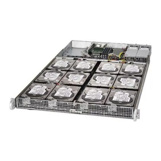
UPER TORAGE YSTEM 5018D2-AR12L/D4-AR12L/D8-AR12L User's Manual Installing and Replacing Hard Drives The chassis can contain twelve 3.5" internal hard disk drives. Each HDD position in the chassis is labeled with a number that corresponds to the SAS/SATA ports on the motherboard. -
Page 75: System Fans
Chapter 6: Advanced Chassis Setup Figure 6-4. Replacing HDDs 3.5" HDD Latch Backplanes Note: numbers above indicate the logical drive locations (drive map). System Fans Six fans provide cooling for the chassis. Figure 6-5. System Fans... -
Page 76: Installing An Expansion Card
UPER TORAGE YSTEM 5018D2-AR12L/D4-AR12L/D8-AR12L User's Manual Replacing a System Fan 1. If necessary, open the top rear cover of the chassis while the system is running to locate the position of the failed fan. Do not run the server for an extended time with the cover off. - Page 77 Chapter 6: Advanced Chassis Setup Installing an Expansion Card 1. Locate the riser card bracket in your chassis accessory bag, and the riser card, which is purchased separately. 2. Power down the system as described in Section 5-2 and remove the rear cover.
-
Page 78: Power Supply
This power supply is auto-switching capable, enabling it to automatically sense and operate at a 100v to 240v input voltage. New units can be ordered directly from Supermicro (see contact information in the Preface). Replacing the Power Supply Replacing the Power Supply With redundant power, the system should keep running if a single power module fails. -
Page 79: Chapter 7 Bios
When an option is selected in the left frame, it is highlighted in white. Often a text message will accompany it. (Note: the AMI BIOS has default text messages built in. Supermicro retains the option to include, omit, or change any of these text messages.) The AMI BIOS setup utility uses a key-based navigation system called "hot keys". -
Page 80: How To Start The Setup Utility
Flashing the wrong BIOS can cause irreparable damage to the system. In no event shall Supermicro be liable for direct, indirect, special, incidental, or consequential dam- ages arising from a BIOS update. If you have to update the BIOS, do not shut down or reset the system while the BIOS is updating. - Page 81 Day MM/DD/YY format. The time is entered in HH:MM:SS format. Note: The time is in the 24-hour format. For example, 5:30 P.M. appears as 17:30:00. The following BIOS items will also be displayed: Supermicro X10SDV-7TP8F Version Build Date Memory Information Total Memory This displays the total size of memory available in the system.
-
Page 82: Advanced Setup Configurations
UPER TORAGE YSTEM 5018D2-AR12L/D4-AR12L/D8-AR12L User's Manual Advanced Setup Configurations Use the arrow keys to select Boot Setup and press <Enter> to access the submenu items. Warning: Take caution when changing the Advanced settings. An incorrect value, a very high DRAM frequency, or an incorrect DRAM timing setting may make the system unstable. - Page 83 Chapter 7: BIOS Wait For 'F1' If Error Use this feature to force the system to wait until the 'F1' key is pressed if an error occurs. The options are Disabled and Enabled. INT19 (Interrupt 19) Trap Response Interrupt 19 is the software interrupt that handles the boot disk function. When this item is set to Immediate, the ROM BIOS of the host adaptors will "capture"...
- Page 84 UPER TORAGE YSTEM 5018D2-AR12L/D4-AR12L/D8-AR12L User's Manual CPU Configuration The following CPU information will be displayed: • Processor ID • Processor Frequency • Processor Max Ratio • Processor Min Ratio • Microcode Revision • L1 Cache RAM • L2 Cache RAM •...
- Page 85 Chapter 7: BIOS Execute Disable Bit (Available if supported by the OS & the CPU) Select Enabled to enable the Execute-Disable Bit which will allow the processor to designate areas in the system memory where an application code can execute and where it cannot, thus preventing a worm or a virus from flooding illegal codes to overwhelm the processor or damage the system during an attack.
- Page 86 UPER TORAGE YSTEM 5018D2-AR12L/D4-AR12L/D8-AR12L User's Manual Note: If a change is made to this setting, you will need to reboot the system for the change to take effect. Refer to Intel’s website for detailed information. Advanced Power Management Configuration This section is used to configure the following CPU Power Management settings.
- Page 87 Chapter 7: BIOS CPU HWPM State Control Enable CPU HWPM Select Enable for better CPU energy performance. The options are Disable, HWPM NATIVE MODE, and HWPM OOB MODE. Enable CPU Autonomous Cstate Use this feature to enable CPU Autonomous C State, which converts HALT instructions to Mwait.
- Page 88 UPER TORAGE YSTEM 5018D2-AR12L/D4-AR12L/D8-AR12L User's Manual CPU T State Control ACPI (Advanced Configuration Power Interface) T-States Select Enable to support CPU throttling by the operating system to reduce power consumption. The options are Disable and Enable. CPU Advanced PM Turning ...
- Page 89 Chapter 7: BIOS Energy Efficient Turbo Use this feature to enable energy efficient turbo mode. The options are En- able and Disable. DRAM RAPL Configuration Override BW_LIMIT_TF This feature allows the user to turn off the "Override BW_LIMIT_TF (Time Frame)"...
- Page 90 UPER TORAGE YSTEM 5018D2-AR12L/D4-AR12L/D8-AR12L User's Manual CPU SLOT 6 PCI-E 3.0 X8 This item configures the link speed of the PCI-E port specified by the user. The options are Gen 1 (Generation 1) (2.5 GT/s), Gen 2 (Generation 2) (5 GT/s), and Gen 3 (Generation 3) (8 GT/s).
- Page 91 Chapter 7: BIOS Memory Configuration Enforce POR Select Enable to enforce POR restrictions on DDR4 frequency and voltage programming. The options are Enabled and Disabled. Memory Frequency Use this feature to set the maximum memory frequency for onboard memory modules. The options are Auto, 1333, 1400, 1600, 1800, 1867, 2000, 2133, 2200, 2400, 2600, 2667, 2800, 2993, 3000, 3200, and Reserved (Do not select Reserved).
- Page 92 UPER TORAGE YSTEM 5018D2-AR12L/D4-AR12L/D8-AR12L User's Manual Memory RAS (Reliability_Availability_Serviceability) Configuration Use this submenu to configure the following Memory RAS settings. Patrol Scrub Patrol Scrubbing is a process that allows the CPU to correct correctable memory errors detected on a memory module and send the correction to the requestor (the original source).
- Page 93 Chapter 7: BIOS XHCI Hand-Off This is a work-around solution for operating systems that do not support XHCI (Ex- tensible Host Controller Interface) hand-off. The XHCI ownership change should be claimed by the XHCI driver. The settings are Enabled and Disabled. EHCI Hand-Off This item is for the Operating Systems that do not support Enhanced Host Controller Interface (EHCI) hand-off.
- Page 94 UPER TORAGE YSTEM 5018D2-AR12L/D4-AR12L/D8-AR12L User's Manual *If the item "Configure SATA as" is set to AHCI, the following items will display: SATA Frozen Use this item to enable the HDD Security Frozen Mode. The options are Disabled and Enabled. SATA AHCI LPM Use this feature to enable the Link Power Management for SATA AHCI.
- Page 95 Chapter 7: BIOS *If the item "Configure SATA as" is set to IDE, the following items will display: SATA Frozen Use this item to enable the HDD Security Frozen Mode. The options are Dis- abled and Enabled. Port 0 ~ Port 4 SATA Device Type (Available when a SATA port is detected) Use this item to specify if the SATA port specified by the user should be con- nected to a Solid State drive or a Hard Disk Drive.
- Page 96 UPER TORAGE YSTEM 5018D2-AR12L/D4-AR12L/D8-AR12L User's Manual Select Enabled to allow a PCI device to generate a PERR/SERR number for a PCI Bus Signal Error Event. The options are Enabled and Disabled. Above 4G Decoding (Available if the system supports 64-bit PCI decoding) Select Enabled to decode a PCI device that supports 64-bit in the space above 4G Address.
- Page 97 Chapter 7: BIOS PCI-E 2.0 X1 OPROM Use this feature to select which firmware type to be loaded for the add-on card in this slot. The options are Disabled, Legacy, and EFI. Onboard SAS Option ROM Use this feature to select which firmware to be loaded for the onboard SAS Option ROM.
- Page 98 UPER TORAGE YSTEM 5018D2-AR12L/D4-AR12L/D8-AR12L User's Manual PXE boot wait time Use this option to specify the wait time to press the ESC key to abort the PXE boot. Press "+" or "-" on your keyboard to change the value. The default setting is 0.
- Page 99 Chapter 7: BIOS COM1 Console Redirection Settings This feature allows the user to specify how the host computer will exchange data with the client computer, which is the remote computer used by the user. Terminal Type This feature allows the user to select the target terminal emulation type for Console Redirection.
- Page 100 UPER TORAGE YSTEM 5018D2-AR12L/D4-AR12L/D8-AR12L User's Manual VT-UTF8 Combo Key Support Select Enabled to enable VT-UTF8 Combination Key support for ANSI/VT100 ter- minals. The options are Disabled and Enabled. Recorder Mode Select Enabled to capture the data displayed on a terminal and send it as text mes- sages to a remote server.
- Page 101 Chapter 7: BIOS function key support. Select ANSI to use the Extended ASCII Character Set. Select VT-UTF8 to use UTF8 encoding to map Unicode characters into one or more bytes. The options are ANSI, VT100, VT100+, and VT-UTF8. Bits Per second Use this feature to set the transmission speed for a serial port used in Console Redirection.
- Page 102 UPER TORAGE YSTEM 5018D2-AR12L/D4-AR12L/D8-AR12L User's Manual Resolution 100x31 Select Enabled for extended-terminal resolution support. The options are Disabled and Enabled. Legacy OS Redirection Resolution Use this feature to select the number of rows and columns used in Console Redi- rection for legacy OS support. The options are 80x24 and 80x25.
- Page 103 Chapter 7: BIOS function key support. Select ANSI to use the extended ASCII character set. Select VT-UTF8 to use UTF8 encoding to map Unicode characters into one or more bytes. The options are ANSI, VT100, VT100+, and VT-UTF8. Bits Per Second This item sets the transmission speed for a serial port used in Console Redirec- tion.
- Page 104 UPER TORAGE YSTEM 5018D2-AR12L/D4-AR12L/D8-AR12L User's Manual This feature Enables the Windows Hardware Error Architecture (WHEA) support for the Windows 2008 (or a later version) operating system. The options are Disabled and Enabled. High Precision Event Timer Select Enabled to activate the High Performance Event Timer (HPET) that produces...
- Page 105 Chapter 7: BIOS TPM Enabled Status TPM Active Status TPM Owner Status TXT Support 7-27...
-
Page 106: Event Logs
UPER TORAGE YSTEM 5018D2-AR12L/D4-AR12L/D8-AR12L User's Manual Intel TXT (Trusted Execution Technology) helps protect against software-based at- tacks and ensures protection, confidentiality and integrity of data stored or created on the system. Use this feature to enable or disable TXT Support. The options are Disabled and Enabled. - Page 107 Chapter 7: BIOS Select Enable for the BIOS to correct a memory error if it is correctable. The options are Disable and Enable. Memory Corr. Error Threshold Use this item to enter the threshold value for correctable memory errors. The default setting is 10.
-
Page 108: Ipmi
UPER TORAGE YSTEM 5018D2-AR12L/D4-AR12L/D8-AR12L User's Manual Note: After making changes on a setting, be sure to reboot the system for the changes to take effect. View SMBIOS Event Log This section displays the contents of the SMBIOS Event Log. IPMI Use this feature to configure Intelligent Platform Management Interface (IPMI) settings. - Page 109 Chapter 7: BIOS Erase SEL Select Yes, On next reset to erase all system event logs upon next system reboot. Select Yes, On every reset to erase all system event logs upon each system reboot. Select No to keep all system event logs after each system reboot. The options are No, Yes, On next reset, and Yes, On every reset.
- Page 110 UPER TORAGE YSTEM 5018D2-AR12L/D4-AR12L/D8-AR12L User's Manual This item displays the sub-network that this computer belongs to. The value of each three-digit number separated by dots should not exceed 255. Station MAC Address This item displays the Station MAC address for this computer. Mac addresses are 6 two-digit hexadecimal numbers.
-
Page 111: Security Settings
Chapter 7: BIOS extended IPMI features. The Disable option is for applications that require faster power on time wthout using Supermicro Update Manager (SUM) or extended IPMI features. The BMC network configuration in the BIOS setup is also invalid when IPMI Function Support is disabled. - Page 112 UPER TORAGE YSTEM 5018D2-AR12L/D4-AR12L/D8-AR12L User's Manual Secure Boot Menu This section displays the contents of the following secure boot features: • System Mode • Secure Boot • Vendor Keys Secure Boot Use this item to enable secure boot. The options are Disabled and Enabled.
- Page 113 Chapter 7: BIOS Key Exchange Key (KEK) Set New Key Select Yes to load the KEK from the manufacturer's defaults. Select No to load the KEK from a file. The options are Yes and No. Append Key Select Yes to add the KEK from the manufacturer's defaults list to the existing KEK. Select No to load the KEK from a file.
-
Page 114: Boot Settings
UPER TORAGE YSTEM 5018D2-AR12L/D4-AR12L/D8-AR12L User's Manual Boot Settings Use this feature to configure Boot Settings: Boot Mode Select Use this item to select the type of device that the system is going to boot from. The options are Legacy, UEFI, and Dual. The default setting is Dual. - Page 115 Chapter 7: BIOS • Dual Boot Order #9 • Dual Boot Order #10 • Dual Boot Order #11 • Dual Boot Order #12 • Dual Boot Order #13 • Dual Boot Order #14 • Dual Boot Order #15 Delete Boot Option Use this feature to remove a pre-defined boot device from which the system will boot during startup.
-
Page 116: Save & Exit
UPER TORAGE YSTEM 5018D2-AR12L/D4-AR12L/D8-AR12L User's Manual Save & Exit Select the Exit tab from the BIOS setup utility screen to enter the Exit BIOS Setup screen. Discard Changes and Exit Select this option to quit the BIOS Setup without making any permanent changes to the system configuration, and reboot the computer. - Page 117 Chapter 7: BIOS Restore Defaults To set this feature, select Restore Defaults from the Save & Exit menu and press <Enter>. These are factory settings designed for maximum system stability, but not for maximum performance. Save As User Defaults To set this feature, select Save as User Defaults from the Exit menu and press <En- ter>.
- Page 118 UPER TORAGE YSTEM 5018D2-AR12L/D4-AR12L/D8-AR12L User's Manual Notes 7-40...
-
Page 119: Appendix A Bios Error Beep Codes
Appendix A: BIOS Error Beep Codes Appendix A BIOS Error Beep Codes During the POST (Power-On Self-Test) routines, which are performed upon each system boot, errors may occur. Non-fatal errors are those which, in most cases, allow the system to continue to boot. - Page 120 UPER TORAGE YSTEM 5018D2-AR12L/D4-AR12L/D8-AR12L User's Manual Notes...
-
Page 121: Appendix B System Specifications
Note: see Section 5-5 for details. Hard Drives Twelve 3.5" internal SATA hard drives Motherboard 5018D2-AR12L: X10SDV-2C-7TP4F (Flex ATX form factor) 5018D4-AR12L: X10SDV-4C-7TP4F (Flex ATX form factor) 5018D8-AR12L: X10SDV-7TP4F (Flex ATX form factor) Dimensions: 9 x 7.25 in (229 x 184 mm) - Page 122 UPER TORAGE YSTEM 5018D2-AR12L/D4-AR12L/D8-AR12L User's Manual System Input Requirements AC Input Voltage: 100 - 240V AC auto-range Rated Input Current: 6-3A Rated Input Frequency: 50 to 60 Hz Power Supply Rated Output Power: 400W (Part# PWS-406P-1R) Rated Output Voltages: +5V (25A), +12V (33A), -12V (0.6A), +3.3V (25A), +5Vsb...
- Page 123 Appendix B: System Specifications Notes...
- Page 124 YSTEM 5018D2-AR12L/D4-AR12L/D8-AR12L User's Manual (continued from front) The products sold by Supermicro are not intended for and will not be used in life support systems, medical equipment, nuclear facilities or systems, aircraft, aircraft devices, aircraft/emergency com- munication devices or other critical systems whose failure to perform be reasonably expected to result in significant injury or loss of life or catastrophic property damage.
Need help?
Do you have a question about the 5018D2-AR12L and is the answer not in the manual?
Questions and answers